 ChipBuddy
← Home
ChipBuddy
← Home
Prerequisites, Inputs & Supported Design Styles
Concurrent macro-plus-standard-cell placement is a powerful step, but it is also unforgiving: it amplifies whatever quality (or lack of it) exists in its inputs. A modern placement engine that positions large hard macros and millions of standard cells in a single optimization pass cannot "fix" a broken netlist, a missing abstract, or an under-sized floorplan. It can only arrange what it is given. This chapter walks through everything that must be in place before you press go, the design states the engine assumes, the taxonomy of design styles you will encounter, and the sanity checks that separate a clean run from a multi-day debugging detour. Think of this chapter as the pre-flight checklist. Pilots do not skip it because they have flown before; neither should you. A disciplined setup phase is, in practice, the cheapest insurance you can buy: the cost of catching a missing abstract or an infeasible utilization target before launch is a few minutes of checking, while the cost of catching the same problem after a multi-hour placement run — possibly compounded by a half-finished clock tree and routing attempt built on top of it — is measured in days. Interviewers probe this topic precisely because it separates engineers who understand why the flow is ordered the way it is from those who merely memorized button sequences.
2.1 What Must Be Ready Before You Run
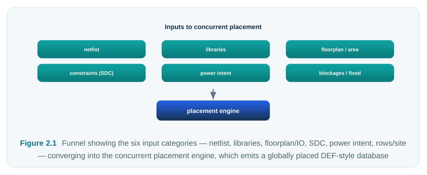
Concurrent placement sits roughly in the middle of the physical-implementation flow. It consumes the outputs of synthesis and early floorplanning and produces a globally placed database that downstream optimization, clock-tree synthesis, and routing depend on. Before launching it, six categories of data must be present and internally consistent.
- 1. A clean synthesized netlist. The gate-level netlist must be functionally complete and free of
dangling logic. Every instance should map to a cell that exists in the libraries. Unresolved references, black boxes without abstracts, and assign statements left over from synthesis will either crash the engine or silently produce nonsense. The netlist defines connectivity, and connectivity is the single most important input the placer reasons about.
- 2. Technology and physical libraries. The engine needs physical abstracts (the LEF-style views)
describing each cell's footprint, pin locations, layer usage, and routing blockages, plus the technology data describing layers, vias, design rules, and the placement site definition. For macros, it also needs the macro abstracts with their pin geometry and internal obstruction layers. Without these, the placer has no notion of how big anything is or where its pins sit.
- 3. The die/core area and IO framework. A floorplan must define the die boundary, the core
(placeable) area, the IO pad or bump framework, and the locations or constraints for top-level pins/ ports. Concurrent placement needs a defined region to place into; an empty or undefined core area is a non-starter.
- 4. Timing constraints (the SDC). Clock definitions, input/output delays, false paths, multicycle paths,
and case analysis tell a timing-driven engine which connections matter. Many concurrent placers weight net lengths by their timing criticality, so an incomplete constraint set produces a placement optimized for the wrong thing.
- 5. Power intent (if multivoltage). For designs with multiple supplies, power gating, or level shifting, a
power-intent description (the generic UPF/CPF-style file) defines voltage areas, power domains, isolation, and special-cell requirements. The placer must respect domain boundaries when positioning both macros and cells.
- 6. A defined row and site structure. Standard cells snap to rows built on a placement site. The rows,
their orientation, and any row-flipping conventions must be established (usually during floorplan initialization) so the engine knows the legal standard-cell grid.
2.2 Design-State Requirements
Having the files is necessary but not sufficient. The state of the design at launch determines whether the engine behaves predictably.
- Legal, consistent library data. Library timing views, physical abstracts, and the netlist must all agree on cell names, pin names, and counts. A mismatch between the timing library and the physical library is one of the most common silent failures.
- Defined rows and site. As above, the core must be tiled with legal rows before cells can be placed legally.
- Blockages. Placement blockages (hard, soft, and partial), routing blockages, and halo/keep-out regions around macros should be defined where the methodology requires them. Concurrent placers can auto-generate macro halos, but explicit blockages give you control over reserved channels and corner regions.
- Pre-placed and fixed objects. Any macro that must sit in a specific location (for example, a memory tied to an IO or a hard IP block with bump constraints) should be marked as fixed or placed before the run. The engine treats fixed objects as immovable obstacles and floats the remaining movable macros and cells around them. Mixing fixed and movable macros is normal and expected.
- Hard constraints. Region constraints, bounds, magnet/guide constraints, and group constraints that the methodology demands should be applied so the engine honors them during global placement rather than being violated and cleaned up later. A useful mental model: the engine sees the world as a set of movable objects, a set of fixed obstacles, and a set of constraints relating them. The cleaner you define those three sets, the better the result. One subtlety worth internalizing is the spectrum between fully fixed, guided, and fully free macros. A fully fixed macro contributes nothing to the optimization except its obstruction. A guided macro carries a soft preference — a suggested region, a bound, or a magnet target — that the engine tries to honor but may relax under pressure. A fully free macro is whatever the optimizer decides. Most healthy mixed-signal-adjacent floorplans use a deliberate blend: anchor the handful of macros that must sit
somewhere for physical reasons, lightly guide the ones with strong architectural intent, and let the engine freely arrange the rest. Over-constraining is a common rookie error; it starves the optimizer of the very freedom that makes a concurrent engine worth running.
2.3 Supported Design Styles
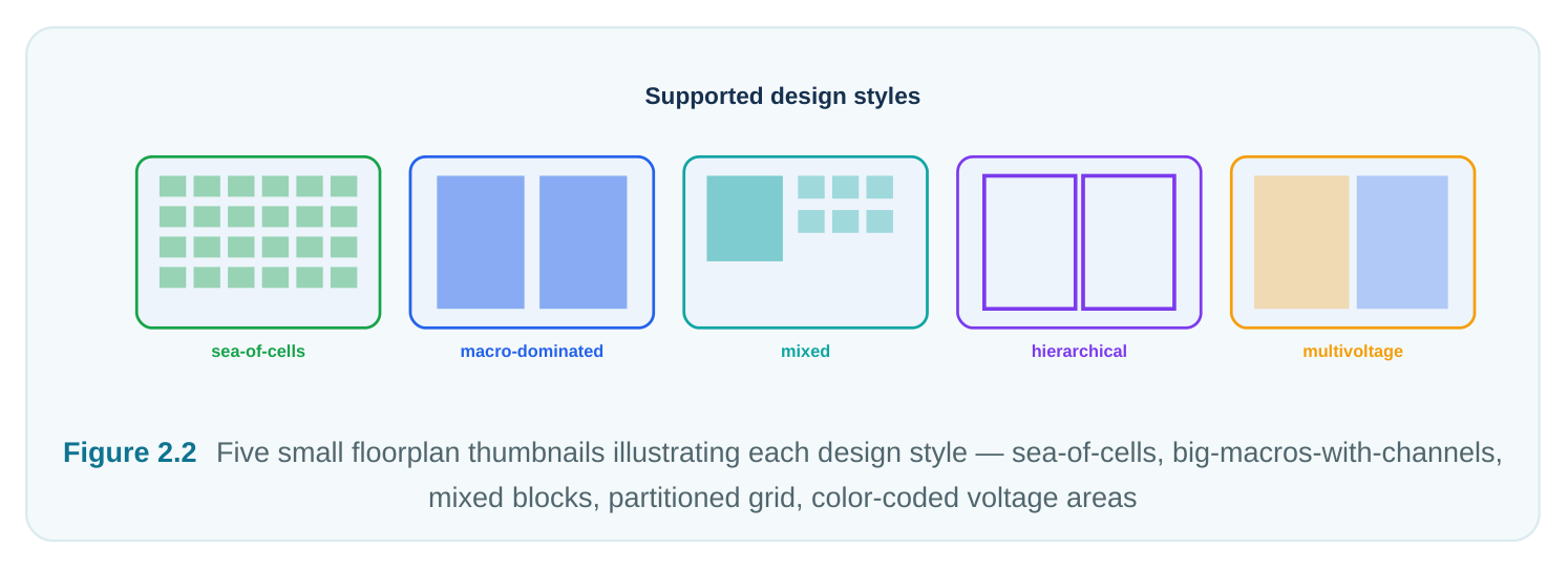
Different designs stress a concurrent placer in different ways. The neutral taxonomy below is engineagnostic; the labels describe the workload, not any tool.
| Design style | Defining characteristic | What it implies for the engine |
|---|---|---|
| Pure standard-cell | No (or only tiny) macros; a sea of small cells | Density and timing dominate; macro handling is irrelevant. Fast, well-behaved. |
| Macro-dominated | A few-to-many large hard macros consuming most core area | Macro arrangement is the hard problem; cell placement is secondary. Channel/halo |
management critical.
| Mixed macro + | Significant counts of both large | The true concurrent problem: co-optimize macro |
|---|---|---|
| standard-cell | macros and many cells | positions and cell positions together. The engine's |
reason for existing.
| Hierarchical / | Design split into blocks/partitions | Each partition is placed within its budget; pin/port |
|---|---|---|
| partitioned | with feedthroughs and interface logic | placement and interface timing become first-class concerns. |
| Multivoltage | Multiple power domains, isolation, level shifters | Domain-aware placement; macros and cells must stay within their voltage areas; special cells placed |
at boundaries. A few practical notes on each:
- Pure standard-cell designs are where placement engines first matured. Here, "concurrent" simply means global cell placement; the macro machinery is dormant.
- Macro-dominated designs (think large memory subsystems) demand that the engine reason about macro aspect ratio, orientation, and the routing channels left between blocks. A bad macro arrangement strands cells in unroutable pockets.
- Mixed designs are the heart of this handbook. The value proposition of a concurrent engine is that it positions macros with knowledge of where the cells connected to them want to be, rather than placing macros blind and discovering congestion later.
- Hierarchical flows add interface complexity: the engine must respect partition boundaries and place top-level pins so that inter-partition timing closes.
- Multivoltage layers domain legality on top of everything else. The placer must never drop a cell into the wrong voltage area, and it must leave room for isolation and level-shifter cells at domain crossings.
2.4 What the Engine Needs to Co-Place Macros and Cells Well
To do macro-plus-cell co-placement intelligently, the engine consumes far more than geometry. The richer and cleaner this information, the better the macros land relative to the logic that talks to them.
| Information | Why the engine needs it |
|---|---|
| Connectivity (the netlist | Determines which macros attract which cells; drives wirelength minimization |
| graph) | and macro grouping. |
| Area / footprint of every | Feasibility and density estimation; decides how tightly objects can pack. |
object
Macro pin geometry Pin-aware macro orientation and placement so connected cells sit near the
| Aspect-ratio / orientation | Tells the engine which macro flips/rotations are legal so it can optimize pin |
|---|---|
| freedom | access and channel formation. |
| Keep-out / halo needs | Reserves space around macros for routing and buffering; prevents cells from |
crowding macro edges.
Timing criticality (from Weights critical nets so they are kept short during co-placement.
Power-domain Ensures objects are placed only within their legal voltage areas. The single most underrated item here is orientation freedom. A macro with a tightly clustered pin group can be flipped or rotated so those pins face the cells that drive and load them, dramatically shortening interface wires. Telling the engine which orientations are legal (and which are forbidden for bump or power-rail reasons) is one of the highest-leverage setup decisions you make. It also helps to give the engine grouping hints where they exist. If you know that a cluster of macros forms a logical subsystem — say, a memory array and its companion controller logic — communicating that affinity (through a region, a group, or a guide) lets the engine keep them together
rather than discovering the relationship the hard way through wirelength alone. The engine will infer a great deal from raw connectivity, but architectural intent that lives only in the designer's head is intent the optimizer cannot use. The art of setup is translating that intent into machine-readable constraints without over-specifying and boxing the optimizer in.
2.5 Readiness Checklist
Run through this before every concurrent placement launch. Treat any "No" as a blocker, not a warning.
# Readiness item Ready? (Y/N)| 1 | Synthesized netlist loads with zero unresolved references |
|---|---|
| 2 | All instances map to cells present in both timing and physical libs |
| 3 | Physical abstracts available for every macro and standard cell |
| 4 | Die/core area, IO framework, and top-level pins defined |
| 5 | Rows and placement site established across the core |
| 6 | SDC reads cleanly; clocks and IO delays defined |
| 7 | Power intent loaded and voltage areas defined (if multivoltage) |
| 8 | Fixed/pre-placed macros marked and located |
| 9 | Placement/routing blockages and macro halos defined |
| 10 | Target utilization is feasible for the core area |
2.6 Inputs Table: Purpose and Consequence if Missing
| Input | Purpose | Consequence if missing or wrong |
|---|---|---|
| Synthesized netlist | Defines logic and connectivity | Engine cannot build the placement graph; crash |
or meaningless result
| Physical abstracts | Footprints, pins, blockages | No size/pin data; placement is impossible or |
|---|---|---|
| (LEF-style) | illegal | |
| Technology data | Layers, vias, site, design rules | No legal grid; row/site errors, illegal placement |
| Floorplan (die/core/IO) | Defines placeable region and | Nowhere to place; immediate failure |
boundaries
Timing constraints Identifies critical connections Timing-blind placement; poor QoR, late surprises
| Power intent | Domains, isolation, special | Domain violations; cells in wrong voltage areas |
|---|---|---|
| (multivoltage) | cells | |
| Rows / site definition | Legal standard-cell grid | Cells cannot be legalized |
| Fixed-macro locations | Anchors hard IP / IO-tied | Engine moves blocks that must not move |
blocks
Blockages / halos Reserve channels and keep- Congestion, unroutable macro edges
2.7 How the Inputs Interact
It is tempting to treat each input as an independent file you simply load, but the failures that cost the most time come from interactions between inputs that are individually valid. A few recurring patterns are worth committing to memory.
- Library and netlist must agree, not merely both exist. Two perfectly valid libraries and a perfectly valid netlist can still be mutually inconsistent if the netlist was synthesized against a different library revision. The symptom — pin or cell mismatches — surfaces only when the engine tries to bind instances to abstracts.
- Floorplan and utilization are coupled to the macro set. A core area that looks generous on paper can be effectively cramped once macros, their halos, and reserved channels are subtracted. Feasibility is always about remaining area for movable logic, not gross area.
- Power intent reshapes the legal placement space. In multivoltage designs the floorplan is no longer a single region; it is a patchwork of voltage areas, each with its own legal occupants. A cell that is fine globally may be illegal locally. Power intent and floorplan must be read together.
- Constraints and timing weighting interact. The SDC does not just check timing later; in a timing- driven concurrent placer it actively steers macro and cell positions during the run. A missing clock or a wrong false-path makes the engine optimize a distorted picture of criticality.
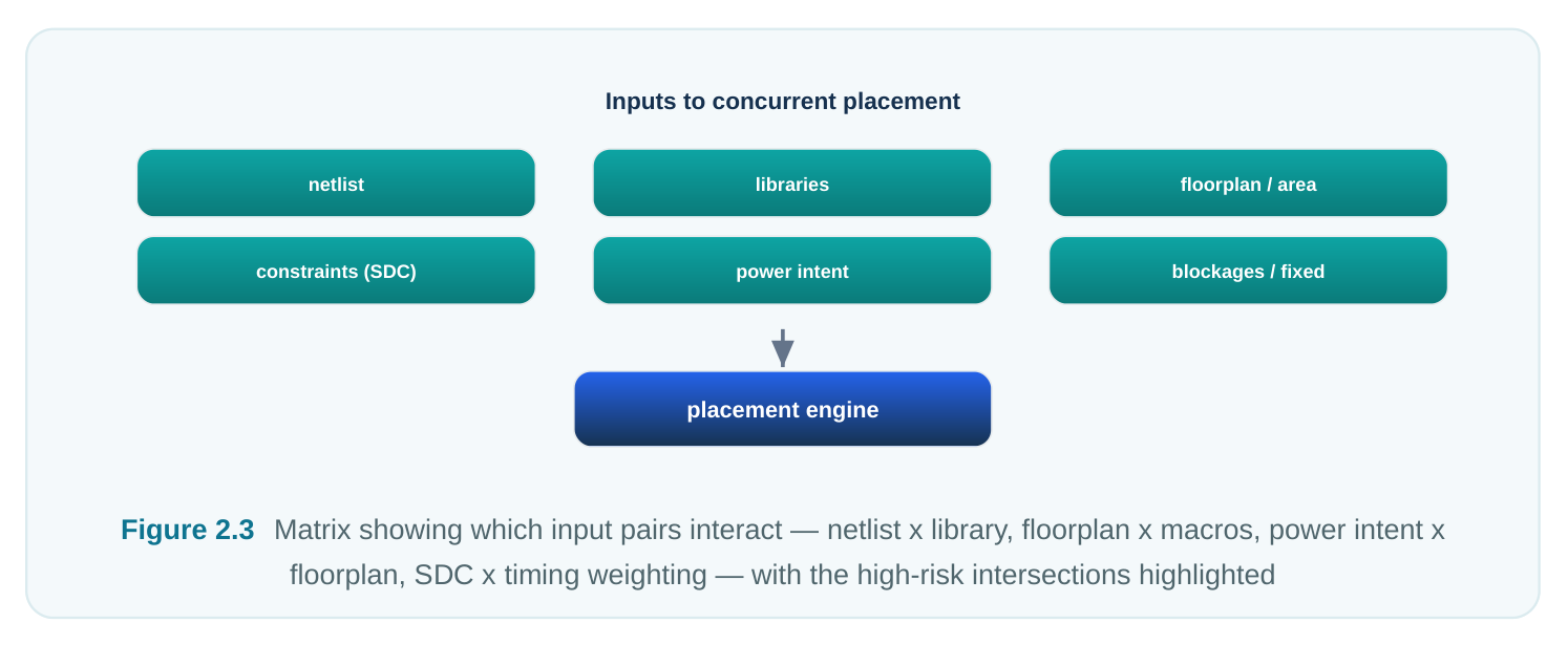
The practical lesson is to validate inputs as a system, not as a stack of files. The sanity checks below are designed with exactly these interactions in mind.
2.8 Sanity Checks Before Launch
Three quick checks catch the vast majority of setup defects.
- 1. Netlist-vs-library consistency. Verify that every instance resolves to a library cell and that pin
names and counts match between the timing and physical views. Library version skew is a classic culprit.
# Generic consistency audit before concurrent placement
check_design -unresolved -unmapped
report_library_mismatch -timing_vs_physical
# Expect: zero unresolved instances, zero pin/cell mismatches- 2. Area feasibility / utilization. Compute whether the movable cell and macro area actually fits the
available core after subtracting macro area, blockages, and reserved channels. If effective utilization is too high, the engine will either fail to legalize or produce congested garbage.
# Estimate feasibility: does the logic fit the core?
report_design_area            ;# total movable cell + macro area
report_core_area              ;# placeable core area
# Rule of thumb: keep post-floorplan effective utilization in a
# methodology-appropriate band (commonly ~60-75% for mixed designs).
set util [get_effective_utilization]
if {$util > 0.80} {
puts "WARNING: utilization $util likely infeasible for mixed placement"
}- 3. Constraint completeness. Confirm clocks are defined, IO delays exist on real ports, and there are
no glaring missing exceptions. A timing-driven placer steered by an incomplete SDC optimizes the wrong nets. A final tip: run these checks every time, even on a database you trust. The most expensive bugs are the ones introduced by a "small" library or netlist update that nobody re-verified.
Interview Q&A
references or black boxes? The engine reasons over the connectivity graph and physical footprints. An unresolved reference has no footprint, no pins, and no defined connectivity behavior, so the engine has nothing to place and nothing to optimize against. It is not a logic-synthesis tool; it does not infer or repair logic. The correct fix is upstream, in synthesis or by supplying the missing abstract.
of view, and why does it matter for mixed placement? A fixed macro is an immovable obstacle: the engine routes cells and other macros around it but never relocates it. A movable macro participates in the optimization and can be repositioned, flipped, or rotated. It matters because real designs mix both — IO-tied or bump-constrained blocks are fixed, while internal memories are often left movable so the engine can co-place them with the logic that connects to them, shortening interface wires and reducing congestion.
their high-fanout or timing-critical pins clustered on one side. By allowing legal flips and rotations, the engine can orient the macro so those pins face the cells that drive and load them, dramatically shortening interface nets and easing channel routing. Forbidding orientations unnecessarily (or, worse, allowing illegal ones that conflict with power rails or bumps) directly degrades QoR.
you check first? Start with feasibility, not the engine. Check effective utilization after subtracting macro area, halos, and blockages — it may simply be too high. Then verify rows/site cover the whole core, that blockages and halos are not over-reserving space, and that fixed macros are not stranding cell area in unroutable pockets. Also confirm voltage-area legality in multivoltage cases, since cells trapped in the wrong domain cannot be legalized. Only after these do you suspect engine settings.
Key Takeaways
- Concurrent placement amplifies input quality; it cannot repair a broken netlist, missing abstracts, or an infeasible floorplan.
- Six input categories must be ready: clean netlist, technology/physical libraries, die/core/IO floorplan, timing constraints, power intent (if multivoltage), and a defined row/site structure.
- The engine models the design as movable objects, fixed obstacles, and constraints — define all three cleanly.
- Design styles (pure standard-cell, macro-dominated, mixed, hierarchical, multivoltage) each stress the engine differently; the mixed style is the engine's core purpose.
- For good macro+cell co-placement, supply connectivity, area, macro pin geometry, orientation freedom, keep-out needs, timing criticality, and power-domain membership.
- Always run the three sanity checks — netlist-vs-library consistency, area/utilization feasibility, and constraint completeness — before every launch, including on trusted databases.
Comments
Leave a Reply