 ChipBuddy
← Home
ChipBuddy
← Home
Concurrent Placement with Multiple Supply Voltages
Concurrent Placement with Multiple Supply Voltages
When a single design carries more than one operating voltage, the comfortable assumptions that underpin ordinary mixed placement quietly fall apart. In a single-voltage flow, the placer is free to drop any standard cell almost anywhere there is legal site capacity, and the only spatial constraints are blockages, edge keep-outs, and the macros themselves. Multiple Supply Voltage (MSV) designs replace that freedom with a strict membership rule: every instance belongs to a power domain, and that domain owns a region of the floorplan. A cell must land inside its own region, never a neighbour's. The placer now has to co-optimize macros, congestion, and timing across the whole die while also respecting an invisible patchwork of voltage territories. This chapter is about doing both at once — placing macros and standard cells concurrently without ever letting a domain's logic stray outside its boundary.
Why MSV Complicates Concurrent Placement
The core difficulty is that MSV layers a partitioning constraint on top of an optimization problem that was already coupled. Concurrent placement already trades macro position against standard-cell congestion and timing. MSV adds the requirement that the standard cells servicing a given block of logic are not globally mobile — they are confined to a sub-rectangle (or a union of rectangles) defined by the voltage area. The placer's global spreading and density-balancing engines, which normally
smear cells across the entire core to equalize utilization, must now spread within each region independently while still treating macros and channels as a shared, die-wide resource. Macros complicate this further because they do not all behave the same way. Some macros are domain-specific: a memory that is powered only when its parent domain is on, and that therefore should sit inside or adjacent to that domain's region so its access logic stays local. Others are always- on — they keep their supply even when surrounding logic is shut down — and these can, and often should, be positioned with different rules, because the rails feeding them differ from the switched rails around them. A common mistake is to treat all hard macros identically and let the engine place an always-on memory deep inside a switchable region, forcing awkward always-on rail routing later. There is a second-order effect worth naming early. Because each region is effectively a smaller placement universe, its local utilization can be far higher than the die-wide average. A region that is only ten percent of the core area but holds twenty percent of the cells will be congested even though the global density looks healthy. Engineers new to MSV often size voltage areas from logical convenience and only later discover that the rectangle is too small once buffering and clock logic are added. Size each voltage area against its post-optimization gate count with headroom, not against the pre-placement netlist, because the placer cannot legally borrow area from a neighbouring region no matter how empty that neighbour is.
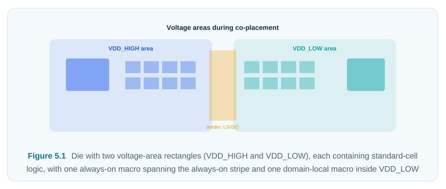
Honoring Voltage Areas During Co-Placement
A voltage area is, mechanically, a named region of the core area bound to a power domain. The placer reads it as a hard spatial constraint: instances assigned to that domain are legal only on sites that fall inside the region's boundary. The interesting engineering is that this constraint must be honored during co-placement, not patched afterward. If you let a global placer ignore voltage areas and then shove out-of-region cells back in as a legalization step, you destroy the timing and congestion picture the placer worked to build — cells arrive at their region edge in a disordered clump. The right behavior is for the analytical/global placement engine to carry the region membership as part of each cell's allowed solution space. The macro placer and the standard-cell spreader cooperate: macros are positioned to leave each region enough contiguous site area for its own logic, and the
spreader equalizes density region-by-region. Congestion is still evaluated die-wide, because routing demand crosses region borders even when cells do not.
# Define two voltage areas, each a rectangle bound to a power domain
create_voltage_area -name VA_HIGH -power_domain PD_HIGH \
-region {120 120 480 600}
create_voltage_area -name VA_LOW  -power_domain PD_LOW \
-region {500 120 880 600}
# Bind logical instances (hierarchies) to their domains so the
# placer knows each cell's legal region before global placement
assign_power_domain -instances u_secure_core/*   -domain PD_HIGH
assign_power_domain -instances u_periph_block/*   -domain PD_LOW
Once domains and regions are bound, the concurrent run treats them as first-class constraints rather than hints:
# Concurrent macro + standard-cell placement that respects
# voltage-area membership for every instance
run_mixed_placement \
-honor_voltage_areas true \
-macro_strategy      concurrent \
-congestion_effort   high \
-density_target      0.72
Boundary Effects: Level Shifters, Isolation, and Channels
The most MSV-specific spatial behavior happens at region borders. Any signal that crosses from one voltage domain to another at a different level needs a level shifter; any signal leaving a switchable domain that feeds an always-on domain needs an isolation cell so the receiving logic sees a defined value when the source is dark. Both cell types are inherently interface cells — logically they belong between two domains, and physically they want to live right at the border. The consequence is predictable: level shifters and isolation cells cluster along region boundaries. If the placer is naïve, these special cells pile up in a thin strip and create a local congestion and legalization hot-spot exactly where two regions also compete for routing tracks. Good practice is to reserve room at borders before the cells arrive — either by lightly de-rating density in a band along each boundary, or by explicitly leaving a placement channel. The interface cells then have somewhere to sit, and the cross-domain nets have tracks to cross on.
# Reserve a low-density band along the shared border so that
# interface cells (level shifters / isolation) have room
set_placement_guidance -region {470 120 510 600} \
-max_density 0.45 -reason interface_cells
# Keep cross-domain interface cells anchored near the boundary
set_interface_cell_constraint -domains {PD_HIGH PD_LOW} \
-snap_to_boundary true -max_offset 30
Pin and channel planning at the border matters because the number of crossing signals sets the width of the channel you need. A wide bus crossing between domains needs both a routing channel and physical room for a row of level shifters; planning that channel during floorplan/placement co-design is far cheaper than discovering the pinch during routing. It also helps to think about which direction a shifter works. A low-to-high shifter and a high-to-low shifter are different cells with different sizes, and a bidirectional interface may need both. When estimating the interface band's area, count the crossing nets by direction, since an asymmetric interface will be dominated by one shifter footprint. The same applies to isolation cells: only nets leaving a switchable domain need them, so a domain that is mostly a receiver needs fewer than one that is mostly a source.
Always-On Logic and Secondary-PG Implications
Always-on cells — retention registers, isolation control, and any logic that must survive a power-down — depend on a continuously live supply. In MSV that often means a secondary power/ground (secondary-PG) connection: the cell sits physically inside a switchable region but draws its backup supply from an always-on rail threaded through that region. Placement cannot ignore this. If always-on cells are scattered randomly through a switchable domain, the always-on rail must snake everywhere to reach them, wasting routing resource and complicating the power grid. The placement-time discipline is to cluster always-on cells along the path the always-on rail will take, so the secondary-PG hookup is short and regular. Many flows let you tag these cells and bias the placer to group them.
# Cluster always-on / retention cells along the always-on rail track
# so secondary-PG hookup stays short during placement
set_always_on_cell_constraint -cells [get_cells -filter "is_always_on==true"] \
-cluster true -align_to_rail AON_VDD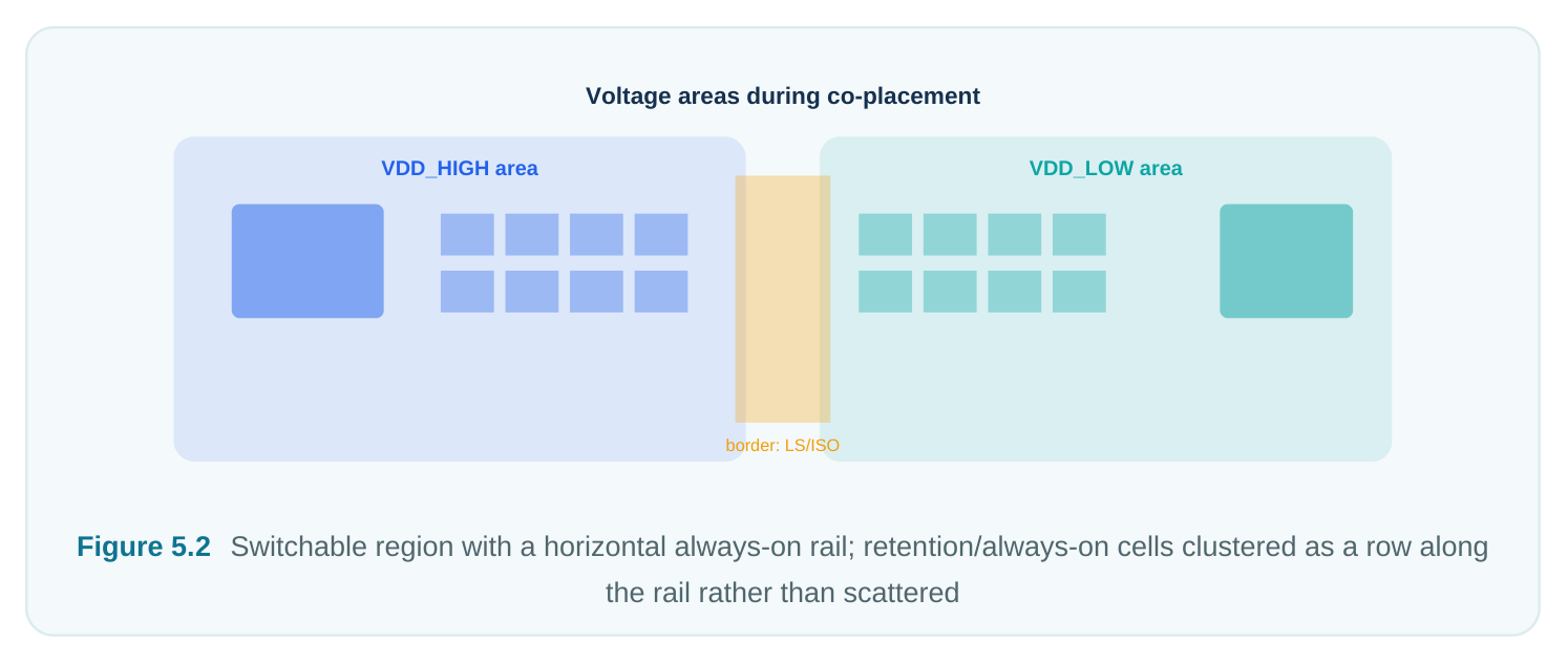
Interaction with Power Planning
In an MSV design, power planning and placement are not sequential — they are concurrent concerns. Each voltage area needs its own rail set carrying its own supply, and switchable regions need their switched rails plus any always-on stripes. The placer must respect the rails as physical obstructions, and the power planner must respect where the placer wants contiguous logic. If rails for the highvoltage region are laid down without knowing where its macros will sit, a macro can land straddling a rail or block a power-switch column. The practical loop: rough macro placement informs where region rails and always-on stripes go; the rail plan then becomes a constraint the concurrent placer honors as it finalizes macro and cell positions. The two converge over a few iterations. Power switches deserve a specific mention. A switchable domain is turned on and off by a fabric of power-switch cells that occupy site area and carry a daisy-chained enable network the placer must not block. If the placer fills a switchable region to maximum density without leaving room for the switch columns, you must either rip up placement later or accept a weaker switch network with more IR drop and slower wake-up. Model the switch columns as placement obstructions up front so the spreader works around them, and develop the switch plan and placement together rather than in series.
MSV placement
Impact if unhandled Mitigation during placement
| Domain cell drifts outside | Illegal placement; spec/ | Carry region membership as a hard |
|---|---|---|
| its voltage area | connectivity violation; cell forced back in a clump | constraint in global placement; verify in- region after every iteration |
| Interface cells crowd the | Local congestion and legalization | Reserve a low-density band / channel at |
| region border | hot-spot at the boundary | borders; snap interface cells near boundary |
| Always-on cells | Long, irregular secondary-PG | Tag and cluster always-on cells along the |
| scattered in a switchable | (always-on rail) routing | always-on rail |
region
| Macro straddles a region | Ambiguous domain ownership; | Constrain macros fully inside one region; |
|---|---|---|
| boundary | rail/region conflicts | treat always-on macros separately |
| Region rails planned | Macros block switch columns or | Co-design rails with rough macro placement; |
| before macro positions | straddle rails | iterate |
known
| Cross-domain bus with | Routing pinch and level-shifter | Plan channel width from crossing-signal |
|---|---|---|
| no planned channel | pile-up at crossing | count during floorplan |
A Worked Conceptual Example
Consider a die with a secure processing block that runs at a higher voltage and a peripheral block that runs lower, plus two memories: one private to the peripheral block and one retention SRAM that must stay alive. The flow proceeds as follows. First, define the two voltage areas as adjacent rectangles and bind each block's hierarchy to its domain (the create_voltage_area / assign_power_domain calls shown earlier). Next, decide macro treatment: the peripheral memory is domain-local and is constrained inside VA_LOW ; the retention SRAM is always-on and is positioned along the always-on stripe rather than buried in the switchable region.
# Domain-local macro: keep the peripheral memory inside VA_LOW
set_macro_constraint -macro u_periph_block/u_sram \
-confine_region VA_LOW -orientation R0
# Always-on macro: place along the always-on stripe, not deep in-region
set_macro_constraint -macro u_secure_core/u_retn_sram \
-align_to_rail AON_VDD -keep_always_on true
# Concurrent run: macros + cells together, voltage areas honored,
# interface band reserved, always-on cells clustered
run_mixed_placement \
-honor_voltage_areas true \
-macro_strategy      concurrent \
-reserve_interface_band true \
-congestion_effort   high
After the run, you check three things in order: that no domain cell sits outside its region, that the border band is not overloaded with interface cells, and that no macro crosses a region edge. Each maps directly to a pitfall below.
| Check | What you query | Pass criterion |
|---|---|---|
| In-region | Cells of each domain vs. its region boundary | Zero out-of-region instances |
membership
| Border health | Density and interface-cell count in the | Density below de-rate target; no |
|---|---|---|
| boundary band | overflow | |
| Macro containment | Each macro's bbox vs. region rectangles | Every macro fully inside exactly one |
region
Pitfalls
A domain cell placed outside its region. This is the cardinal MSV sin. It can creep in when buffers or clones are inserted after the region constraint was set, or when legalization nudges a cell across a boundary. Always re-verify in-region membership after any optimization step that creates or moves cells, not just once at the end. Border congestion. Because level shifters and isolation cells are drawn to the boundary, the band between regions becomes the busiest, most contested strip on the die. If you did not reserve room, you get a legalization pile-up exactly where routing is also tightest. Reserve the band early; it is cheap insurance. A macro straddling a region boundary. A hard macro whose bounding box crosses from one voltage area into another has ambiguous domain ownership and almost certainly fouls the rail plan. Constrain every macro to live wholly inside one region — and handle always-on macros as a deliberate, separate case rather than letting the generic engine decide.
Under-sized voltage areas. A region drawn from logical neatness rather than a realistic postoptimization gate count runs hot and fails to legalize, while a neighbour sits half-empty and unable to help. Check per-region utilization, not just die-wide density, and re-size boundaries early. Remember to include interface cells in the budget: level shifters and isolation cells are real area that does not exist in the pre-placement netlist, so estimate their count from the crossing-signal list before the concurrent run, not after.
Interview Q&A
back inside? Because legalizing voltage-area violations after the fact destroys the timing and congestion structure the placer built. Cells dragged back to their region arrive as a disordered clump at the border, creating local congestion and re-introducing timing problems. The region constraint has to be part of the global placement solution space from the start, so cells are spread legally within their region as they are placed.
on cells (retention registers, isolation control) need a continuously live supply, typically through a secondary-PG connection to an always-on rail that runs through an otherwise switchable region. If they are scattered, that always-on rail must reach everywhere, wasting routing and grid resource. The fix is to tag them and cluster them along the always-on rail's path so the secondary-PG hookup is short and regular.
are interface cells between two domains, so they naturally cluster at region boundaries. That makes the border band the busiest part of the die, colliding with the routing channel the cross-domain nets also need. You mitigate it by reserving a lower-density band or explicit channel at the boundary and snapping interface cells near it, so both the cells and their crossing nets have room.
done separately? Each voltage area needs its own rail set, switchable regions need switched rails plus always-on stripes, and the placer must treat all of these as obstructions. If rails are planned before macro positions are known, a macro can straddle a rail or block a power-switch column; if macros are placed without knowing the rails, the same conflict appears from the other side. They must be co-designed iteratively: rough macros inform rails, then the rail plan constrains the concurrent placer.
Key Takeaways
- In MSV, every instance belongs to a power domain and must be placed inside that domain's voltage area; this membership is a hard constraint, not a hint.
- Region membership must be carried into global/concurrent placement so cells spread legally within their region — never patched afterward by legalization.
- Macros differ: domain-local macros stay inside their region, while always-on macros are positioned along always-on rails as a deliberate separate case.
- Level shifters and isolation cells crowd region borders; reserve a low-density band or channel there before they arrive.
- Cluster always-on cells along the always-on rail to keep secondary-PG hookup short and regular.
- Power planning and placement are concurrent: co-design region rails and always-on stripes with macro placement, iterating to convergence.
- Always verify three things after the run: zero out-of-region cells, a healthy border band, and no macro straddling a boundary.
Comments
Leave a Reply