 ChipBuddy
← Home
ChipBuddy
← Home
Macro Placement Constraints
In concurrent macro and standard-cell placement, the placement engine is free to move both macros and the cell sea simultaneously, optimizing wirelength, congestion, and timing in one pass. That freedom is powerful, but unconstrained freedom is dangerous: an engine left to its own devices will happily wedge a memory against the die edge with its pins facing a wall, stack twelve identical blocks into an unroutable cliff, or leave a 200-nanometer slot between two macros that no router can ever fill. The constraint toolbox exists to fence the optimizer into the region of manufacturable, routable, closable solutions while still letting it explore. This chapter walks through that toolbox one constraint at a time. For each, we cover why it exists, what effect it has on the solution, and a generic command you would issue. The command names here are deliberately neutral — every commercial flow has its own spelling, but the concept transfers directly. Treat the syntax as pseudo-code that maps onto whatever your tool calls it.

4.1 Placement Halos (Keep-Out Margins)
A halo, also called a keep-out margin or placement blockage ring, is a band drawn around a macro's boundary into which the engine may not place standard cells (and usually not other macros either). It travels with the macro — if the macro moves, the halo moves with it, which is exactly what you want during concurrent placement when macros are still fluid. Why it exists. Macro edges are where pins live. If standard cells pack right up to the macro boundary, three bad things happen. First, the pin-access region becomes congested before the router even starts, because the cell pins and the macro pins compete for the same nearby tracks. Second, there is no room to land the macro's signal pins onto higher metal layers without immediately jogging around cells. Third, power straps and the macro's own ring/rail connections need clearance. A halo reserves a quiet collar of space so the router has somewhere to breathe. Effect on the solution. The engine treats the halo as soft-blocked area for cells. Utilization in that band drops to zero, pushing the surrounding cell cloud slightly outward. This costs a little wirelength but buys routability. Halos are typically asymmetric: you often want a wider margin on the pin side(s) and a thinner margin on the blank sides.
# Generic halo: inner=left, outer=bottom, etc. Units in microns.
# Wider band on the pin-bearing side, narrower elsewhere.
set_macro_halo -macro u_sram_0 -left 4.0 -right 2.0 -top 2.0 -bottom 5.0
# Apply a uniform halo to every macro matching a pattern
set_macro_halo -macro [get_macros u_cache_*] -all_sides 3.0
A common rookie mistake is to set halos so wide that the macros can no longer fit at the target utilization — the engine then either spreads macros to the corners or fails to legalize. Size the halo to a few routing pitches plus your power-strap pitch, not to a round "looks safe" number.
4.2 Macro Orientation Constraints
Every macro can be placed in one of eight orientations: the four 90-degree rotations, each optionally mirrored (flipped). The notation R0/R90/R180/R270 plus MX/MY (mirror-X, mirror-Y) is the usual shorthand. An orientation constraint restricts which of these the engine may use. Why it exists. Two reasons dominate. First, pin-side facing: most hard macros concentrate their signal pins on one or two edges. You want those pin edges to face into the routing channel or toward the core, never toward the die boundary or toward an abutting macro's blank back. Second, row/site compatibility and power: a macro's power rails and its allowed flip are tied to the standard-cell row orientation it abuts, so only certain flips keep the rails aligned and the antenna/well rules legal. Effect on the solution. Constraining orientation shrinks the engine's search space per macro. Done well, it guarantees pins face channels and improves pin-access routability dramatically. Done badly — for example forcing a single orientation on a macro the engine wanted to flip — you can trap pins against a wall and create a congestion hot spot.
| Orientation token | Meaning | Typical use |
|---|---|---|
| R0 | No rotation, no flip | Default; pins face core |
| R180 | 180-degree rotation | Pins flipped to opposite edge |
| MX | Mirror about X axis | Rail-align to flipped cell row |
| MY | Mirror about Y axis | Pin side faces left channel |
| R90 / R270 | 90-degree rotations | Tall macro turned for aspect fit |
# Allow only the two orientations whose pin edge faces the channel
set_macro_orientation -macro u_sram_0 -allowed {R0 MY}
# Force a fixed orientation when you know exactly how it must sit
set_macro_orientation -macro u_phy_top -fixed R180
4.3 Macro Array Constraints
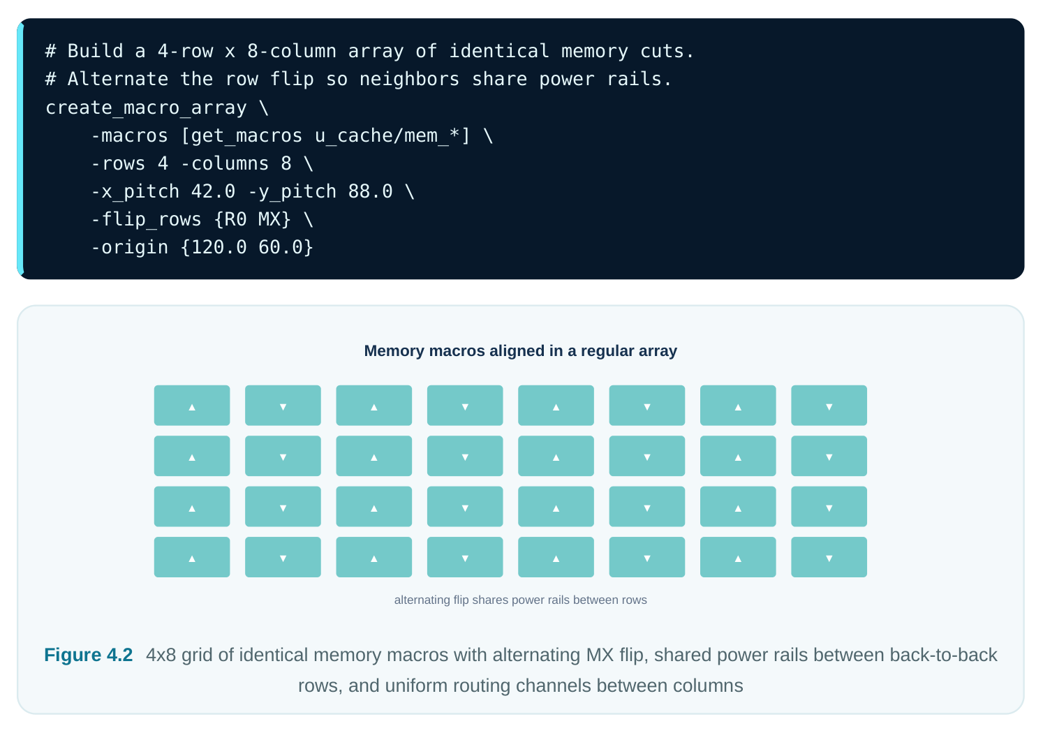
When a design contains many identical macros — a register file built from sixteen copies, or a cache made of thirty-two memory cuts — letting the engine scatter them independently produces a chaotic floorplan that is hard to route and harder to supply power to. An array constraint tells the engine to arrange a named set of identical macros into a regular grid: equal pitch, consistent orientation pattern, aligned edges. Why it exists. Regular arrays give regular routing and regular power. When memories line up on a fixed pitch, the data and address buses run as clean parallel bundles, the power straps cross every macro at the same offset, and the channels between rows are uniform and predictable. Irregular
placement of the same cells forces the router to fan signals in every direction and leaves awkward leftover gaps. Effect on the solution. The engine places the group as a structured block: you specify rows, columns, pitch, and often an alternating flip pattern (so adjacent macros share power rails back-toback). This is a strong constraint — it removes most of the per-macro freedom — so it is reserved for genuinely identical, bus-connected macros where regularity is worth more than per-instance optimization.
4.4 Fixed and Pre-Placed Macros; Guidance Regions
Not every macro should be optimized. Some have a physically determined location: an I/O PHY that must sit next to its bump pads, an analog block on a quiet substrate corner, a hard IP whose location is dictated by the package or by a previous tape-out. For these you use a fixed (locked, pre-placed) constraint. For macros that have a preferred neighborhood but can still wiggle, you use a softer guidance region (soft guide / bounding box). Why fixing exists. A fixed macro is removed from the optimization entirely: the engine plans the cell sea and the remaining macros around it. This is essential when a location is non-negotiable for electrical, package, or reliability reasons. The flip side: every fixed macro is a hard wall the optimizer must work around, so over-fixing strangles the engine and produces detours and congestion.
Why guidance exists. A guidance region expresses intent without dictating coordinates. You say "keep this macro group in roughly the lower-left quadrant"; the engine honors that as a soft attraction but is free to slide within the box to relieve congestion or shorten critical nets. This is the workhorse for steering concurrent placement — you get designer judgment plus engine optimization.
| Mechanism | Hardness | Engine freedom | When to use |
|---|---|---|---|
| set_fixed | Hard | None — locked | Package/IO/analog mandated location |
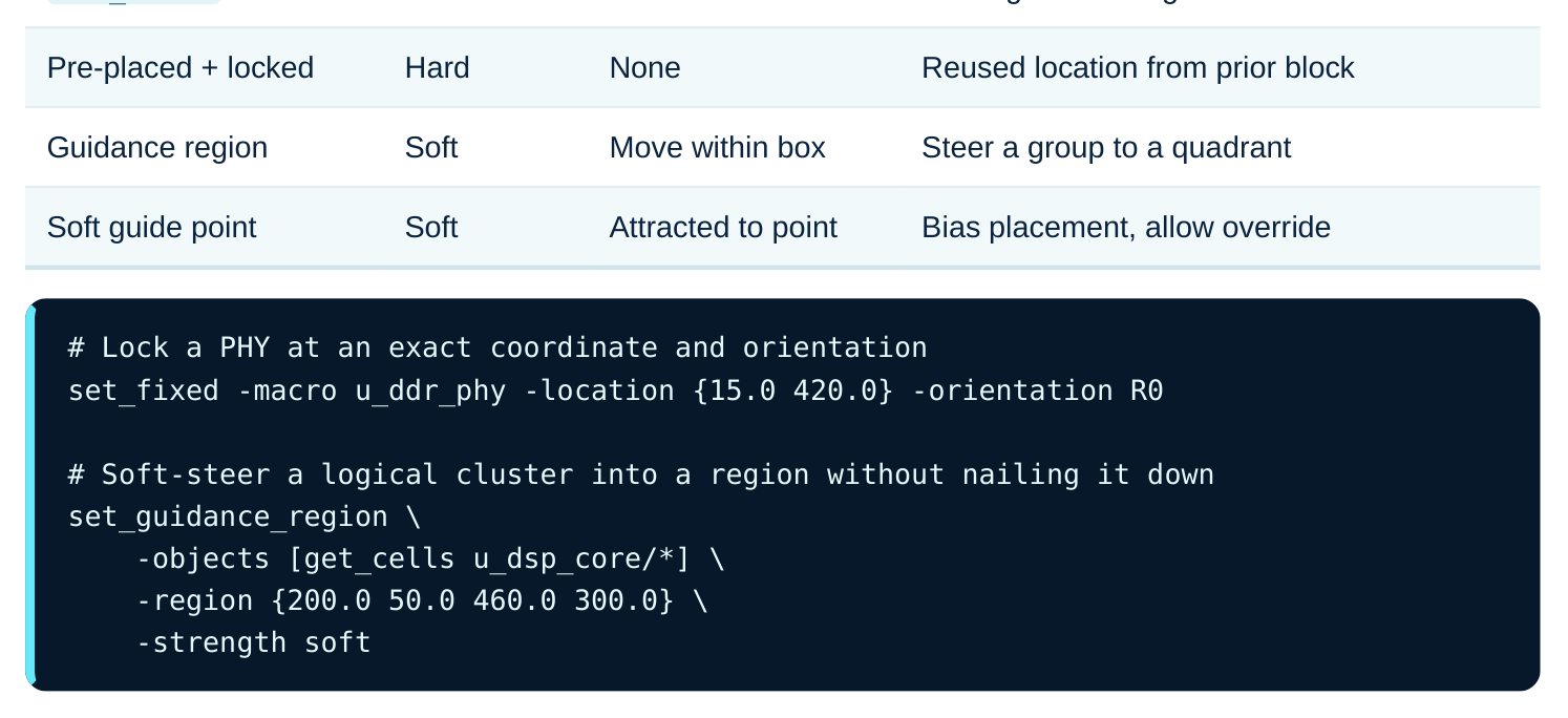
A useful discipline: fix only what is truly immovable, and express everything else as guidance. If you find yourself fixing dozens of macros to "help" the engine, you have stopped doing concurrent placement and started doing manual placement with extra steps.
4.5 Spacing Constraints and Channel Width
A spacing constraint sets the minimum (and sometimes maximum) distance between macro edges. Closely related is the explicit notion of channel width — the open corridor between two macros or between a macro and a row block, reserved for routing and power. Why it exists. Two macros placed too close leave a channel too narrow to route the nets that must pass through it, or too narrow to drop the power straps that feed the surrounding logic. But macros placed too far apart waste area and lengthen the very buses you were trying to shorten. The spacing constraint encodes the Goldilocks zone. Channel sizing is fundamentally a routing-demand calculation: estimate how many wires and straps must cross the gap, multiply by pitch, add via and DRC clearance, and that is your minimum width. Effect on the solution. Minimum spacing prevents the unroutable-slot pathology; the engine will refuse to push two macros closer than the floor you set. Combined with halos, spacing constraints define the routing fabric between macros, not just around them. A subtle interaction: halo + halo + minspacing can compound, so check that your effective channel equals what you intended.
# Floor on the gap between any two macros
set_min_spacing -from [get_macros u_*] -to [get_macros u_*] -distance 6.0
# A wider dedicated channel where a major bus and power must cross
set_min_spacing -from u_sram_0 -to u_sram_1 -distance 18.0 \
-reason "addr/data bus + 2 power straps"
A practical estimation rule of thumb for a channel that must carry N signal wires plus P power straps:
| Term | Contribution to channel width |
|---|---|
| Signal wires | N x (wire pitch) |
| Power straps | P x (strap pitch) |
| Via landing / DRC | fixed clearance both sides |
| Margin for jogs | ~10-20% of the above |
4.6 Maximum Stacking Length (Avoiding Long Walls)
When several macros abut edge-to-edge in a straight line, they form a continuous wall. A short wall is fine. A long wall is a router's nightmare: every signal that needs to get from one side to the other must detour all the way around the end of the wall, because there is no channel through it. A maximum stacking length (or max-abutment) constraint caps how many macros — or how many microns — may sit in an unbroken row before the engine must insert a channel. Why it exists. Long unbroken macro walls split the routing area into isolated pockets. Nets that straddle the wall blow up in length and pile congestion at the wall's ends. Worse, clock and power distribution cannot cross cleanly. By forcing a break every few macros, you guarantee periodic channels for routing, power, and clock to pass through. Effect on the solution. The engine inserts spacing breaks so that no abutted run exceeds the limit. You trade a small amount of area (the inserted channels) for global routability. This constraint pairs naturally with array constraints — you set the array pitch and a stacking cap so even the regular grid gets through-channels.
# No more than 3 macros may abut before a routing channel is forced
set_max_stacking_length -macros [get_macros u_cache/mem_*] \
-max_count 3 -break_channel 12.0
# Alternatively express the cap in microns of unbroken edge
set_max_stacking_length -macros [get_macros u_*] -max_length 320.0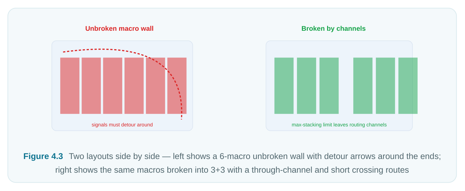
4.7 Group Constraints (Keep-Together)
A group constraint tells the engine that a named set of objects — macros, cells, or both — belongs together and should be placed as a cohesive cluster. It is the placement expression of logical hierarchy or functional locality. Why it exists. Cells and macros that talk to each other heavily should be physically near each other; spreading a tightly-coupled function across the die inflates wirelength and wrecks timing. Grouping also keeps a reused IP's standard-cell "glue logic" next to the macro it serves, and keeps power/clock domains contiguous so they can be supplied and gated as a unit. Effect on the solution. The engine adds an attraction (or a soft bounding box) that pulls the group's members together during optimization. Unlike a fixed region, a group constraint usually does not pin a location — it preserves relative togetherness while the cluster as a whole is free to find its best spot. Overusing groups can fight the engine's global wirelength optimization, so reserve them for genuinely cohesive functions.
# Keep a macro and its surrounding glue logic together as one cluster
set_group -name dsp_cluster \
-objects [list u_dsp_mem [get_cells u_dsp_core/*]] \
-keep_together -strength medium| Group strength | Behavior | Use when |
|---|---|---|
| Soft | Gentle attraction | Mild locality preference |
| Medium | Strong attraction, can stretch | Function + its glue logic |
| Hard | Bounded box, cannot escape | Domain isolation required |
4.8 The Master Constraint Table
This is the table worth memorizing for an interview. It maps each constraint to its purpose, where you typically reach for it, and — critically — what goes wrong if you misuse it. Interviewers love the last column, because it shows you understand constraints as trade-offs rather than magic switches.
| Constraint | Purpose | Typical use | Risk if misused |
|---|---|---|---|
| Halo / keep-out | Reserve quiet collar for pin access and power | Around every hard macro | Too wide → cannot legalize; too narrow → pin congestion |
| Orientation | Face pins toward channels; keep rails aligned | Pin-heavy macros near edges | Over-constrain → pins trapped against walls |
| Array | Regular grid for identical bus-connected macros | Memory/register-file banks | Applied to non-identical macros → wasted area, poor timing |
| Fixed / pre- | Lock electrically/package- | I/O PHY, analog, | Over-fixing → engine detours, |
| placed | mandated locations | reused IP | congestion, lost optimization |
| Guidance | Soft-steer a group to a | Quadrant-level floor- | Box too tight → behaves like a |
| region | neighborhood | planning intent | hard fix |
| Spacing / | Guarantee routable, power- | Between adjacent | Too small → unroutable slot; too |
| channel | feedable gaps | macros | large → wasted area |
| Max stacking | Break long unroutable | Rows of abutted | Cap too high → walls; too low → |
| length | macro walls | memories | fragmented, area-heavy |
| Group / keep- | Preserve functional locality | Macro + its glue logic together | Overuse → fights global wirelength optimization |
4.9 Putting It Together: A Worked Snippet
In practice these constraints are layered. A typical concurrent-placement constraint deck for a cache subsystem might read like this — note how halo, orientation, array, stacking, spacing, and a fixed PHY all coexist.
# 1. Lock the PHY where the package demands
set_fixed -macro u_ddr_phy -location {15.0 420.0} -orientation R0
# 2. Halo every memory cut; wider on the pin (bottom) edge
set_macro_halo -macro [get_macros u_cache/mem_*] \
-left 3.0 -right 3.0 -top 3.0 -bottom 6.0
# 3. Pins face the core channel only
set_macro_orientation -macro [get_macros u_cache/mem_*] -allowed {R0 MX}
# 4. Lay the cuts into a regular array with alternating flip
create_macro_array -macros [get_macros u_cache/mem_*] \
-rows 4 -columns 8 -x_pitch 42.0 -y_pitch 88.0 \
-flip_rows {R0 MX} -origin {120.0 60.0}
# 5. Break the array so no more than 4 abut without a channel
set_max_stacking_length -macros [get_macros u_cache/mem_*] \
-max_count 4 -break_channel 14.0
# 6. Reserve a wide channel for the data bus + power on the edge
set_min_spacing -from u_cache/mem_31 -to u_ddr_phy -distance 20.0
# 7. Keep the cache controller glue logic with its memories
set_group -name cache_cluster \
-objects [list [get_macros u_cache/mem_*] [get_cells u_cache_ctl/*]] \
-keep_together -strength medium
Read in order, this deck first removes the immovable object from the problem, then shapes the routable fabric around the memories (halo, orientation, array, stacking, spacing), then ties the controlling logic to the data it serves (group). That layering — immovable first, fabric second, locality last — is a clean mental model to recite when asked how you would set up a block.
Interview Q&A
in concurrent placement the macros are still moving. A keep-out tied to absolute coordinates would protect a patch of die that the macro has already left, while the macro's new location would have no protection at all. A halo bound to the macro's boundary guarantees the pin-access and power collar is always exactly where the pins currently are, no matter how the engine slides the macro around during optimization.
congestion are worse. What happened, and what would you do? Every fixed macro is a hard obstacle the optimizer cannot move, so the engine lost the ability to trade macro position against wirelength and congestion — it is now routing the cell sea through a maze it cannot reshape. The fix is to fix only the genuinely immovable macros (I/O PHY, analog, package-mandated IP) and re-express
the rest as soft guidance regions. That returns the engine's freedom while preserving designer intent, which is the whole point of concurrent placement.
calculation, not a guess. Count the signal wires that must cross the channel and multiply by the wire pitch; add the number of power straps that must drop there times the strap pitch; add fixed via-landing and DRC clearance on both edges; then add roughly 10-20% margin for jogs. Cross-check that halos on both macros plus the minimum spacing actually sum to that target, because those terms compound and can silently leave you short.
pairwise spacing says nothing about global routability. A long run of abutted macros forms a continuous wall: every net that must cross it detours around the ends, exploding wirelength and piling congestion at the wall extremities, and clock/power cannot pass through cleanly. Capping stacking length forces periodic through-channels so routing, power, and clock can cross the macro region at regular intervals, keeping the whole block routable rather than just locally legal.
Key Takeaways
- Constraints fence the optimizer into manufacturable, routable solutions without taking away its ability to explore — the goal is steering, not manual placement.
- Halos protect pin access and power; they move with the macro and are usually asymmetric (wider on the pin side). Too wide breaks legalization, too narrow re-creates congestion.
- Orientation constraints make pins face channels and keep power rails aligned; over- constraining can trap pins against walls.
- Array constraints bring regularity — uniform pitch, aligned buses, predictable power — for genuinely identical, bus-connected macros only.
- Fix only the truly immovable; steer everything else with soft guidance regions. Over-fixing strangles the engine and is the single most common self-inflicted wound.
- Spacing and channel width are routing-demand calculations, not round numbers; halos and spacing compound, so verify the effective gap.
- Maximum stacking length breaks long unroutable walls, guaranteeing periodic through- channels for routing, power, and clock.
- Group constraints preserve functional locality; reserve them for cohesive functions so they don't fight global wirelength optimization.
- Layer constraints in order: immovable first, routable fabric second, locality last — a clean, recitable mental model for setting up any block.
Comments
Leave a Reply