 ChipBuddy
← Home
ChipBuddy
← Home
Buffering Routed Nets & Group Repeater Insertion
By the time a design reaches the post-route ECO stage, the easy buffering opportunities are long gone. Early in the flow, when nets are still virtual flight-lines, dropping a buffer is almost free: the placer finds a gap, the router has not committed any metal, and timing closure tools insert thousands of buffers without anyone thinking twice. The story changes completely once detailed routing exists. The net is no longer an abstraction — it is physical metal pinned to specific tracks, threading through vias, sharing routing resources with hundreds of neighbors. Inserting a buffer into that wire is surgery, not sketching. This chapter is about doing that surgery cleanly: how to break into a routed net, place a buffer or a whole coordinated chain of repeaters, and re-stitch the connection without provoking violations elsewhere. This is one of the most heavily probed topics in physical-design ECO interviews, precisely because it sits at the intersection of timing, placement legality, and routing. A candidate who only knows "the tool inserts a buffer" will struggle the moment the interviewer asks what physically happens to the wire.
Why Post-Route Buffering Is Hard
On an unrouted net, buffering is a logical-and-placement operation. You add a cell instance, the netlist now has two segments instead of one, and the router will later figure out the metal. Nothing existing gets damaged because nothing existing was committed. On a routed net, every one of those assumptions breaks:
- The metal already exists. The wire occupies real tracks. To insert a buffer mid-net, the tool must rip up a segment of that wire, free the tracks, drop the buffer onto a legal placement site, and then re-route two short connections — driver-to-buffer-input and buffer-output-to-load. This rip-and- reconnect is the defining difficulty.
- Tracks are occupied by neighbors. The freed corridor may immediately be wanted by the new stub connections, but the surrounding congestion may leave no room. A buffer that is logically perfect but cannot be wired in is useless.
- Placement sites may be taken. Post-route, the floorplan is dense. The ideal location — say, the geometric midpoint of a long net — may have no free site. The tool must search outward for the nearest legal, non-overlapping site, which moves the electrical breakpoint away from the optimum.
- Everything must be re-validated locally. New cell, new pin loading, new wire segments — parasitics change, and the timing on this net (and its neighbors via coupling) must be re-extracted and re-timed.
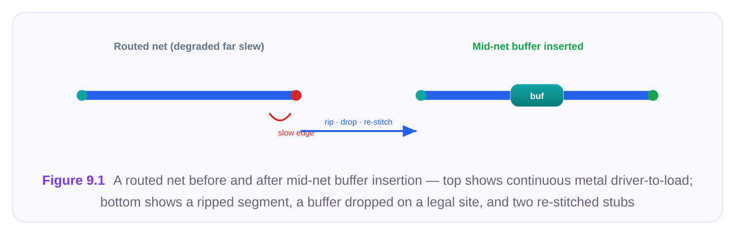
The table below contrasts the two regimes so the distinction is unambiguous in an interview.
| Aspect | Unrouted-net buffering | Routed-net buffering |
|---|---|---|
| State of the net | Logical / flight-line | Committed detailed metal |
| Primary operation | Add instance, defer routing | Rip segment, place, re-stitch |
| Placement freedom | High — many open sites | Low — dense, sites contested |
| Routing impact | Router handles globally | Incremental reroute, local only |
| Risk to neighbors | Minimal | Coupling, congestion, DRC nearby |
| Verification needed | Global re-route + STA | Local re-extract + incremental STA |
A Minimal Mid-Net Insertion
The generic command for the surgical case takes the target net, a buffer reference cell, and a hint location. The tool rips, places, and re-stitches as one atomic operation.
# Insert a single buffer into an already-routed net near a hint point.
# The tool rips the local segment, finds a legal site, and reroutes the stubs.
insert_buffer_on_route \
-net        net_data_q_27 \
-cell       BUFX4 \
-near_point {412.50 880.10} \
-reroute    incremental \
-honor_routing_rules true
# If the chosen site sits far from the hint, the stub reroute can be inspected:
reroute_net -net net_data_q_27 -mode incremental -report_detour true
Note the -reroute incremental flag. We are explicitly telling the engine not to re-route the whole net
from scratch — only to wire the two new stubs and patch back into the surviving metal. A full reroute at this stage would needlessly disturb a wire that was probably hand-tuned or hold-balanced, and could ripple into neighbors. It helps to picture exactly what the engine does between the call and the result. First it locates the point on the existing routed net nearest the hint coordinate and breaks the metal there, freeing a short corridor of tracks. Second it searches the placement grid outward for the first legal site — on a valid row, snapped to grid, not overlapping another instance, and not on a hard blockage. Third it orients the buffer so its input faces the upstream stub and its output the downstream stub. Fourth it routes the two stubs under the original net's routing rules, preserving widths, spacing, and any shielding. Only if all four steps succeed does the operation commit; otherwise a well-behaved engine rolls back rather than leaving a half-broken net. When you debug a failed insertion, that model tells you which stage to interrogate: a placement failure points at site availability, a routing failure points at congestion. A subtle trap is the gap between the hint point and the actual breakpoint. Engineers reason about the electrical optimum — "split this net at its midpoint" — but the tool snaps to the nearest legal site, which in a congested region may be tens of microns away. That displacement shifts the resistive split, so the realized delay improvement is smaller than predicted. Always read back the achieved location before trusting the timing number.
Long Interconnect and Why Repeaters Are Mandatory
To understand group repeater insertion you first have to internalize why a single buffer is sometimes not enough. The delay of a distributed RC wire does not grow linearly with length — it grows roughly with the square of length. A wire of length L has resistance proportional to L and capacitance proportional to L, and the dominant Elmore-style delay term scales as R·C, hence as L². Double the length and the unbuffered delay roughly quadruples.
The fix is to chop the long wire into shorter pieces and drive each piece with a fresh repeater. If you split a wire into k equal segments, each segment is length L/k, so each contributes delay proportional to (L/k)², and there are k of them. Total wire delay scales as k·(L/k)² = L²/k — it falls linearly as you add repeaters, at the cost of k repeater delays added back. The optimum trades the shrinking wire term against the growing buffer term, which is why long nets converge on a chain of evenly spaced repeaters of a chosen drive strength rather than one giant buffer.
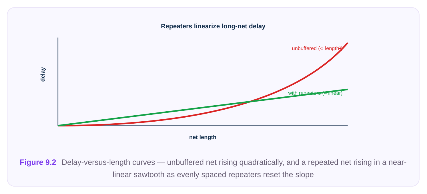
Two design choices fall out of this:
- Spacing. There is an optimal segment length set by the per-unit wire R and C and the repeater's intrinsic delay and input capacitance. Below that spacing you spend too many buffers; above it the wire term dominates again.
- Drive strength. A larger repeater has lower output resistance (drives the next segment faster) but higher input capacitance (loads the previous segment more) and more area and leakage. The chain is tuned so each repeater is strong enough for its segment but no stronger. The table summarizes the levers and the trade each one pulls against. Lever Increase it to... Cost / counter-pressure Number of repeaters Cut total wire delay (L²/k) Adds k buffer delays, area, leakage Repeater drive Lower output resistance, faster Higher input cap loads prior stage, more strength segment power Segment spacing Fewer cells, less area Wire term grows quadratically again Wire width / layer Lower R, faster propagation More routing resource, possible track shortage
Group / Bus Repeater Insertion
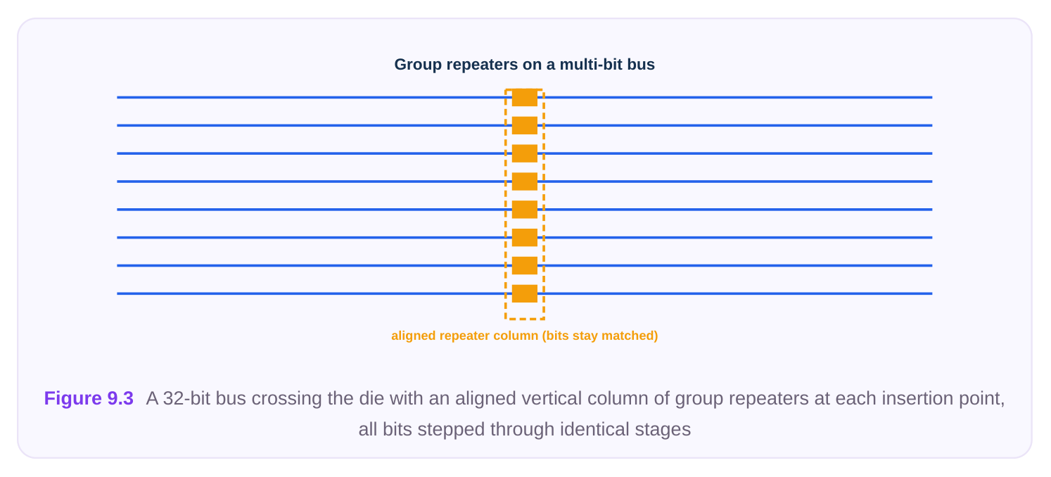
Now scale the single-net case up to a multi-bit bus. A 32-bit data bus running across the die is really 32 long parallel nets with near-identical geometry. If you buffer them one at a time with independent decisions, you will get skew: bit 7 might receive a chain of four BUFX4 repeaters while bit 8 gets three BUFX6, and now the bits arrive at different times. For a bus, matching across bits is often as important as raw delay. Group repeater insertion treats the bus as a unit. The tool inserts a coordinated set of repeaters — the same number, same drive, same spacing, ideally aligned in a tidy column — across all bits at once, so the bits stay balanced. This both preserves bit-to-bit matching and produces clean, routable structures instead of a tangle of independently optimized chains. Before invoking such an operation, run prerequisite checks. Group insertion fails badly if the bus is not actually a clean set of point-to-point nets, or if there is no room for an aligned repeater column.
# Validate that the bus is a legal candidate for coordinated repeater insertion.
check_repeater_prereq \
-bus        {data_out[*]} \
-require_single_load   true \
-require_no_feedthrough true \
-check_site_column at {1200.00 *} width 8 \
-report  bus_prereq.rpt
Typical prerequisites the check enforces:
- Each bit is a simple driver-to-single-load net (or at least has a well-defined load) — no fan-out branching mid-bus that would make uniform repeaters meaningless.
- A legal placement corridor exists where an aligned column of repeaters can sit on legal sites without overlaps or blockage conflicts.
- The power grid reaches that corridor so every inserted repeater can be tied to supply and ground.
- No special routing rule (shielding, non-default width) on the bus would be silently violated by the new stubs. Once prerequisites pass, the coordinated insertion is a single call. You specify the bus, the desired number of repeater stages or a target spacing, and the cell, and the engine places a matched chain on every bit.
# Insert a coordinated, bit-matched chain of repeaters across the whole bus.
insert_repeater_group \
-bus        {data_out[*]} \
-cell       BUFX6 \
-stages     3 \
-spacing    auto_optimal \
-align_column true \
-match_across_bits true \
-reroute    incremental \
-tie_supply automatic
After insertion, always query what was actually created. The tool's site search may have shifted some repeaters off the ideal column, or skipped a bit that had no legal site, and you need to know.
# Inspect the inserted repeaters: counts, locations, drive, and any per-bit
deviation.
query_repeaters -bus {data_out[*]} -show_location true -show_drive true \
-flag_unmatched_bits true -report repeater_audit.rpt
If query_repeaters flags an unmatched bit — say bit 19 got only two stages because a site was blocked — you have a skew problem to resolve before signoff, either by freeing a site and re-running, or by accepting and re-timing. There is a deeper reason group insertion matters beyond tidiness. A bus is frequently constrained by relative timing rather than absolute timing: the receiving logic latches all bits together, so what fails timing is the spread between the earliest and latest bit, not any one bit's path. If you buffer bits independently, even a tool that closes each bit's setup time can widen that spread, because the per-bit optimizer has no incentive to keep the bits aligned. Group insertion makes matching a first-class objective. When the stages, drive, and spacing are identical across bits and the cells sit in an aligned column, the systematic component of skew collapses to whatever small differences remain in the original wire geometry. This is also why aligned columns are valued for their own sake — beyond looking clean, a column of identical repeaters at the same x-coordinate experiences nearly identical local parasitics and temperature, which further tightens matching. Coupling deserves a specific mention on buses. Parallel bus bits are strong aggressors and victims of one another. Inserting repeaters resets the driver strength on each segment, which changes how each bit responds to crosstalk from its neighbors. A coordinated insertion keeps those crosstalk interactions symmetric across the bus; an ad-hoc one can create a bit whose weaker driver makes it unusually susceptible to a neighbor's switching. This is one more argument for treating the bus as a unit and for re-extracting with coupling capacitance enabled after insertion.
Practical Flow and Cautions
Stitching the above into a disciplined ECO procedure:
- 1. Identify the need. Failing transition/slew on a long net, or a max-delay violation dominated by wire
delay, or a bus with bit-to-bit skew. Distinguish "needs one buffer" from "needs a repeater chain" from "needs a coordinated bus group."
- 2. Check feasibility first. Run
check_repeater_prereqfor buses, and for single nets confirm a legal
site exists near the target. Never assume the geometric optimum is available post-route.
- 3. Insert with incremental reroute. Use
insert_buffer_on_routeorinsert_repeater_groupwith
-reroute incremental so only the local stubs are touched.
- 4. Verify supply hookup. Every inserted cell must connect to power and ground rails. A buffer placed
in a region the power grid does not cover is a fatal, sometimes silent, error — confirm the rows have rails and the cell snapped to them.
- 5. Re-extract parasitics, then re-time. New cells and new metal change RC. Run incremental
extraction over the affected region and incremental STA to confirm the fix helped and created no new setup/hold or transition violations, including on coupled neighbors.
- 6. Check DRC locally. The rip-and-reroute can create spacing or via violations in the immediate
vicinity. Run incremental DRC on the touched area. The cautions worth memorizing: site availability constrains where you can insert, which constrains how close to optimal your timing fix can be; supply hookup is non-negotiable and easy to forget; and reextract/re-time is not optional — an unbuffered-mental-model engineer who skips re-extraction will report a fix that does not exist in the real parasitic picture. A few more practical hazards round out the picture. Repeaters inserted into a long net invert or preserve polarity depending on the cell — a chain of inverting repeaters must contain an even count to keep logical sense, whereas non-inverting buffers are free of that constraint but cost slightly more delay per stage. Know which cell type your library and constraints assume. Watch leakage budgets too: a wide bus times many repeater stages can add a surprising amount of always-on leakage
current, and on a power-sensitive block that can matter more than the area. Finally, respect any layer or net-class intent on the original net. A net that was deliberately promoted to a thick upper-metal layer for low resistance should have its stubs routed on a compatible layer; letting the incremental router drop the stubs onto a thin lower layer reintroduces exactly the resistance the original routing tried to avoid, partially defeating the buffering. When the ECO is for hold rather than setup, the same machinery applies but the intent inverts: you are inserting delay deliberately, often a chain of small buffers on a short path, and the placement and reroute concerns are identical even though the timing goal is opposite. The commands do not change; only your target does.
Interview Q&A
unrouted net the buffer is just a new instance and the router lays metal later, so nothing existing is disturbed. On a routed net the wire is committed metal on real tracks. Insertion must rip a segment of that wire, find a legal placement site (which may be scarce in a dense post-route floorplan), drop the buffer there, and incrementally reroute two short stubs back into the surviving metal — all without breaking neighbors via congestion, coupling, or DRC. It is a rip-and-restitch surgery rather than a free logical add.
the spacing? Distributed RC wire delay grows with the square of length because both R and C scale with length. One big buffer at the start cannot fix the wire's own L² term — the wire downstream of it still degrades quadratically. Splitting the wire into k segments, each driven by a fresh repeater, makes total wire delay scale as L²/k, falling linearly with repeater count, at the cost of k repeater delays. The optimal spacing balances the shrinking wire term against the growing buffer-delay term, and is set by per-unit wire R and C against the repeater's intrinsic delay and input capacitance.
long parallel nets with similar geometry. Buffering them independently yields different stage counts and drive strengths per bit, producing bit-to-bit skew and messy routing. Group repeater insertion inserts a coordinated, matched set — same number of stages, same drive, aligned spacing — across all bits at once, preserving matching and producing clean, routable aligned columns. It is the difference between 32 independently optimized chains and one balanced bus structure.
happened? Before: confirm each bit is a clean driver-to-load net with no problematic mid-bus fanout, confirm a legal aligned placement corridor exists, confirm the power grid reaches it for supply hookup, and confirm no special routing rule will be violated — typically via check_repeater_prereq . After: run query_repeaters to audit counts, locations, and drive per bit and flag any unmatched bit whose site was blocked. Then re-extract parasitics, run incremental STA and DRC. Never trust the insertion blind — the site search can shift or skip cells.
Key Takeaways
- Post-route buffering is a rip-and-restitch operation: free the metal, place on a legal site, incrementally reroute the stubs — not a free logical add like on unrouted nets.
- Use incremental reroute so you patch only the local stubs and leave the rest of the carefully built net and its neighbors undisturbed.
- Wire delay grows with length squared; long nets need a chain of evenly spaced repeaters, with spacing and drive tuned to balance wire delay against added buffer delay.
- For buses, insert repeaters as a coordinated group so all bits get matched stages, drive, and spacing — preventing bit-to-bit skew and yielding clean, routable columns.
- Always run prerequisite checks before group insertion (
check_repeater_prereq) and audit the result afterward (query_repeaters) to catch shifted or skipped cells. - Never skip supply hookup and re-extract-plus-re-time; a buffer with no rail connection or an un-re- extracted net is a fix that does not exist in the real silicon picture.
Comments
Leave a Reply