 ChipBuddy
← Home
ChipBuddy
← Home
Power- & Multivoltage-Aware ECO
Every engineering change order (ECO) you make late in the physical-design flow lands on top of a power architecture that was carefully planned during floorplanning and synthesis. By the time you are inserting a buffer to fix a hold violation or swapping a gate to close a setup path, the chip already has its voltage domains drawn, its power-gating switches placed, and its special cells (level shifters, isolation cells, retention flops, always-on buffers) stitched into the supply network. A multivoltage (MV) ECO is therefore never just a logical edit. It is a logical edit that must be reconciled with the physical power intent. This chapter explains why that reconciliation matters, what goes wrong when engineers ignore it, and how to perform a change that is correct against both timing and power.
Why the Power Architecture Constrains Every ECO
A modern SoC is partitioned into power domains. Each domain has a nominal operating voltage, a primary power net, and a primary ground net. Some domains are switchable: a header or footer switch network can disconnect the domain's virtual supply to save leakage when the block is idle. Other domains stay live and form the always-on fabric. On top of this sit special cells whose entire purpose is to make domain boundaries safe:
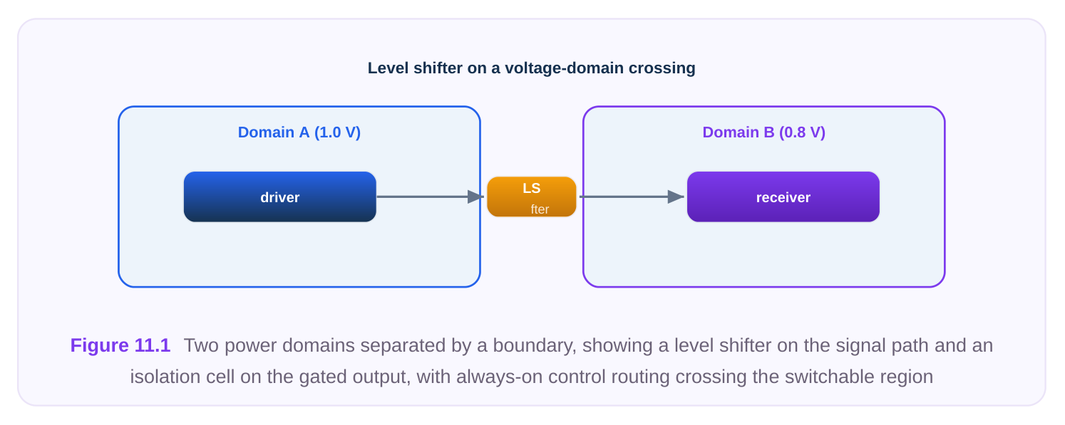
- Level shifters translate a logic signal from one voltage to another so a low-voltage driver can correctly drive a high-voltage receiver (and vice versa).
- Isolation cells clamp the outputs of a domain that is about to be powered down so the still-live receiving domain never sees a floating, mid-rail value.
- Always-on buffers carry control signals (enables, isolation controls, retention saves) through a switchable region without losing their value, because they are tied to the always-on supply even where they sit physically.
- Retention flops keep state alive on a low-leakage backup supply while the main supply is gated off. The crucial point for ECO work: these structures encode rules. A signal that crosses from a 0.72 V domain to a 0.99 V domain must pass through a level shifter. A signal leaving a domain that can be powered down must be isolated before it enters an always-on consumer. If your ECO adds a cell, moves a driver, or reroutes a net so that it now crosses a boundary it did not cross before, you may have silently broken one of these rules. The tool will not infer the fix for you during a manual ECO; it will only flag the violation afterward, if you remember to check. It helps to internalize why the original flow placed these cells where it did. During implementation, the power intent description (the machine-readable specification of domains, supplies, switches, and special-cell rules) drives an automated insertion pass that guarantees every legal crossing is protected. A manual or scripted ECO operates outside that automated pass: you are editing the netlist directly, and nothing re-runs the insertion logic on your behalf. This is the single most important mental shift for late-stage MV work. The safety net that protected the original design is not active during your edit; you must reconstruct that protection by hand and then prove it with the rule checker.
Supply Nets for Newly Added ECO Cells
Standard cells in a multivoltage design connect to more than the obvious VDD/VSS. Depending on the cell type and the domain it lives in, a cell may have a primary supply pair and one or more secondary pins:
Primary power/
Cell type Secondary connection Why
Ordinary logic in always-on Always-on VDD / VSS none Simple, never gated
| Logic in switchable domain | Virtual (switched) | none | Powers off with the |
|---|---|---|---|
| VDD / VSS | domain | ||
| Always-on buffer placed in | Always-on VDD / VSS switchable region | none, but routed from AON rail | Must survive shutdown |
| Level shifter | Both domain supplies | input-side and output- | Bridges two voltages |
side rails
| Isolation cell | Receiver supply | isolation enable from | Clamps during |
|---|---|---|---|
| AON | shutdown | ||
| Retention flop | Switched supply for | backup/retention supply logic | Holds state when gated |
When you place an ECO cell, the placer gives it a location, but the supply binding is governed by the power intent, not by geometry alone. A cell physically sitting inside a switchable region is, by default, associated with that region's switched supply. If you intended it to be always-on, the default binding is wrong. After any structural ECO you must re-resolve the supply network so every new instance is bound to the correct rails and its secondary pins are connected.
# After placing ECO cells, re-resolve the supply network so every
# new instance picks up the correct primary and secondary supplies
update_supply_nets
# Confirm the binding on a specific ECO instance before signoff
report_supply_net -instance eco_buf_2417
A frequent and painful mistake is to add a cell, route it, and assume that because it placed cleanly it is also powered correctly. Placement legality and supply correctness are independent. A level shifter that is physically legal but missing its second supply pin connection is a non-functional cell. There is a subtle corollary worth stating explicitly. Secondary-pin connections are usually made by special routing layers or by power-grid stitching rather than by ordinary signal routing. That means a cell can look complete in the signal-route view while its secondary supply pin is still dangling. When you re-resolve supplies, the tool establishes the logical association between the pin and the correct supply net; a follow-up power-route step then physically connects it. Skipping either half leaves you with a cell that is logically bound but physically unconnected, or physically near a rail but logically unbound. For signoff you need both: the supply-net report should show the intended net, and the physical connectivity check should show the pin reaching that net's metal.
Common Multivoltage Violations Introduced by ECOs
Careless ECOs tend to reintroduce the exact violations the original power planning was designed to prevent. Four show up again and again.
- 1. Missing level shifter on a domain crossing. You buffer a long net or duplicate a driver, and the
new path now originates in one voltage domain and terminates in another with no level shifter in between. The signal may simulate fine in a unit delay model but will be slow, marginal, or nonfunctional at silicon corners. The fix is to insert a level shifter of the correct direction (low-to-high or high-to-low) on the offending segment.
# Insert a level shifter on a net that now crosses a voltage boundary
insert_level_shifter \
-net        data_path_q \
-from_domain pd_core_low \
-to_domain   pd_io_high \
-direction   low_to_high \
-location near_sink- 2. Missing isolation on a gated output. Your ECO creates or reconnects a signal that leaves a
switchable domain and feeds an always-on consumer, but the path bypasses the existing isolation. When the source domain powers down, the consumer sees a floating output. Insert an isolation cell with the correct clamp value (clamp-high or clamp-low, per the design's reset semantics) controlled by the always-on isolation enable.
# Add isolation on a gated-domain output feeding an always-on block
insert_isolation \
-net        ctrl_out \
-domain     pd_gated_engine \
-enable     iso_en_aon \
-clamp      0 \
-location on_source_boundary- 3. Wrong supply binding. The new cell is connected to the switched rail when it should be always-on,
or to the wrong domain's supply entirely. This is the classic consequence of skipping update_supply_nets . The cell either dies when its region powers down (if it should have lived) or it is needlessly always-on (wasting leakage and possibly violating the AON cell budget). The fix is to rebind: associate the instance with the correct domain or explicitly mark it always-on, then re-resolve.
- 4. Always-on logic placed in a switchable region without an always-on connection. Control logic,
isolation enables, and retention save/restore signals must stay live. If your ECO places such logic in a region that gets gated and binds it to the switched supply, the control collapses exactly when it is needed most. The fix is to use always-on buffers/cells routed from the AON rail, even though they sit inside the switchable area. A useful diagnostic habit is to ask, for every cell you add, two questions: In which voltage does this cell operate? and Must this cell stay alive when its physical region is gated? The first question catches
missing level shifters; the second catches missing always-on bindings and missing isolation. If you cannot answer both questions confidently for a given ECO instance, you are not ready to sign that change off. The violations above are rarely the result of not knowing the rules; they are the result of skipping the two-question check under schedule pressure and trusting that a clean placement implies a clean power state.
| Violation | Root cause in the ECO | Corrective action |
|---|---|---|
| Missing level shifter | New path crosses a voltage | insert_level_shifter , correct direction |
boundary
| Missing isolation | Gated output now feeds live | insert_isolation , correct clamp + AON |
|---|---|---|
| logic | enable | |
| Wrong supply binding | Skipped supply re-resolution | Rebind domain, then update_supply_nets |
| AON logic on switched | Control cell placed in gated rail | Use always-on cell from AON rail region |
After applying fixes, never trust your memory of what you changed. Run the rule checker over the affected region or the whole design.
# Verify the change against the full multivoltage rule set
check_mv_rules -domains all -report eco_mv_check.rpt
# Narrow to the touched region for a fast iteration loop
check_mv_rules -region eco_bbox -severity error
Power-Integrity-Aware ECO
Functional correctness is only half the obligation. Every cell you add draws current, and that current flows through the same power grid as everything else. A cluster of ECO buffers dropped into an already-congested region can pull the local rail voltage down (IR drop) or push wire current density past the electromigration (EM) limit. The result is a path that meets timing in the static analysis but fails at the real, drooped supply voltage, or a rail segment that degrades over the product lifetime. Three habits keep ECOs power-integrity-clean:
- 1. Spread the load. Avoid concentrating many new high-drive cells in one spot. If a fix needs several
buffers, distribute them rather than stacking them over one weak grid region.
- 2. Respect the grid context. Prefer ECO sites that sit over robust power straps, not over grid gaps or
near the edges of a switchable region where virtual-rail resistance is highest.
- 3. Re-check the rails after the change. Treat rail analysis as part of ECO signoff, not a separate
later step.
# Static IR-drop and EM check on the region affected by the ECO
analyze_rail \
-mode      static \
-region    eco_bbox \
-metrics   {ir_drop em_current} \
-report    eco_rail.rpt
# Dynamic check if the ECO touched a high-switching, clock-adjacent area
analyze_rail -mode dynamic -region eco_bbox -report eco_rail_dyn.rpt
Read the report against the same thresholds the original signoff used. If an ECO pushes worst-case IR drop past the budget, you have not actually fixed timing; you have moved the problem from the timing report to the silicon. The honest response is to relocate or resize the cells, or to add a short powerstrap stitch, before declaring the ECO done. There is also a switching-activity dimension that static analysis can miss. A handful of buffers on a lowtoggle data net contribute little dynamic current. The same buffers on a high-frequency, high-activity net — or near the clock distribution — can cause a transient droop that only a dynamic, vector-driven rail analysis exposes. As a rule of thumb, escalate from static to dynamic rail checking whenever the ECO touches clock-adjacent logic, large simultaneous-switching buses, or the region near a power switch where virtual-rail resistance is already high. The cost of a dynamic run is far cheaper than a respin caused by a droop-induced functional failure that no static check would ever have flagged.
Before — IR hotspot After — relieved dense cluster of added buffers
A Conceptual Flow for a Multivoltage-Safe ECO
The discipline that prevents almost every MV ECO escape is to fold power awareness into the change loop rather than bolting it on afterward. A reliable sequence looks like this:
- 1. Identify intent. Before editing, know which domains the affected nets touch and which are
switchable. A timing fix that stays inside one always-on domain is low risk; one that crosses a boundary or enters a gated region demands extra care.
- 2. Make the structural change. Add, remove, or swap cells to address the timing or DRC issue,
placing new cells at power-integrity-friendly sites.
- 3. Re-resolve supplies. Run
update_supply_netsso every new instance binds to the correct
primary and secondary rails for its domain.
- 4. Repair boundary cells. Where the change created new crossings, add level shifters; where it
created new gated-to-live paths, add isolation; where it placed control logic in gated regions, use always-on cells.
- 5. Check MV rules. Run
check_mv_rulesand resolve every error before looking at timing again. - 6. Check rail integrity. Run
analyze_railover the touched region; confirm IR drop and EM stay
within budget.
- 7. Re-verify timing and DRC. Only now is the timing/DRC result trustworthy, because it rests on a
correct power picture.
- 8. Document the delta. Record which cells, supplies, and special cells changed so the next engineer
(and the next ECO) inherits an accurate intent. The ordering matters. Checking timing before fixing supplies gives you optimistic numbers built on an illegal power state. Checking rails before adding the special cells gives you a current picture that the final design will not match. Power-aware ECO is fundamentally about doing the power steps inside the loop, not after it.
# A compact driver for one ECO iteration
update_supply_nets
check_mv_rules  -region eco_bbox -severity error -report mv.rpt
analyze_rail    -mode static -region eco_bbox -report rail.rpt
# Gate the next step on a clean result
if {[file_has_errors mv.rpt] || [rail_over_budget rail.rpt]} {
puts "ECO not signoff-clean; fix MV/rail before re-timing"
}
Interview Q&A
and routed fine. What power-related cause would you check first? Check the supply binding. A buffer placed inside a switchable region binds by default to the switched (virtual) rail. If the path was meant to stay live, or if the buffer's region powers down during the failing scenario, the cell is nonfunctional exactly when needed. Run update_supply_nets , confirm the instance is on the intended rail, and verify with the supply-net report. Also confirm the buffer did not create a new domain crossing that now lacks a level shifter.
need each? A level shifter translates voltage between two domains operating at different supply levels so the signal is electrically valid; you need one whenever an ECO creates a path crossing a voltage boundary. An isolation cell clamps a signal to a known value while its source domain is powered off so a still-live receiver never sees a floating input; you need one whenever an ECO creates or reroutes a path from a switchable domain into an always-on (or other live) consumer. A single boundary can require both: a level shifter for voltage and an isolation cell for shutdown safety.
this still be wrong? Concentrated drive current can create a local IR-drop or EM hotspot. The static timing run uses nominal supply, but at the drooped local voltage the cells are slower and the "passing" path may fail in silicon; meanwhile the wire current density may exceed EM limits and degrade over the product lifetime. The fix is to run analyze_rail on the region, then spread the cells, relocate them over stronger straps, or stitch additional power, until IR drop and EM are within the original signoff budget.
only meaningful on a correct underlying state. If you check timing before re-resolving supplies, you get optimistic numbers built on illegal or wrong-rail connections. If you check rails before inserting the required level shifters and isolation cells, the current picture omits cells the final design will include. The correct order is: structural change, re-resolve supplies, repair boundary cells, check MV rules, check rail integrity, then re-verify timing and DRC. Doing power steps inside the loop, not after it, is what prevents silent escapes.
Key Takeaways
- An MV ECO is a logical edit plus a reconciliation with the power architecture; placement legality and supply correctness are independent.
- Every new cell must bind to the correct primary and secondary supplies for its domain; always run
update_supply_netsafter a structural change. - The four recurring violations are missing level shifters, missing isolation, wrong supply binding, and always-on logic on a switched rail. Fix them with
insert_level_shifter,insert_isolation, and correct rebinding. - Added cells draw current; use
analyze_railto confirm the ECO did not create IR-drop or EM hotspots, judged against the original signoff budget. - Fold the power steps into the ECO loop in the right order: change, re-resolve supplies, repair boundary cells,
check_mv_rules,analyze_rail, then re-verify timing. Document the delta for the next engineer.
Comments
Leave a Reply