 ChipBuddy
← Home
ChipBuddy
← Home
Local Timing Fixes: Resizing, Buffering & Fanout
Chapter 8 — Local Timing Fixes: Resizing, Buffering & Fanout
By the time a block reaches the ECO stage, the global optimization moves are over. Placement is frozen in spirit if not in law, the clock tree is built, and the routes are largely committed. What remains is a list of stubborn paths — a handful of nanoseconds of setup violation here, a few picoseconds of hold there — that the bulk engines either could not reach or created as a side effect of their own fixes. This is the world of local timing fixes: surgical, path-by-path changes that nudge a single stage of logic without disturbing the neighborhood around it. There are really only three everyday levers an engineer reaches for when correcting a timing violation locally: resizing a cell, inserting a buffer or inverter, and restructuring the fanout of a net. Almost every manual setup or hold fix you will ever make at the ECO stage is some combination of these three. The art is knowing the physics behind each, predicting how a move affects setup and hold simultaneously, and applying it with the least possible damage to everything else. This chapter builds that intuition and gives you a decision framework you can defend in an interview.
Lever 1 — Cell Resizing
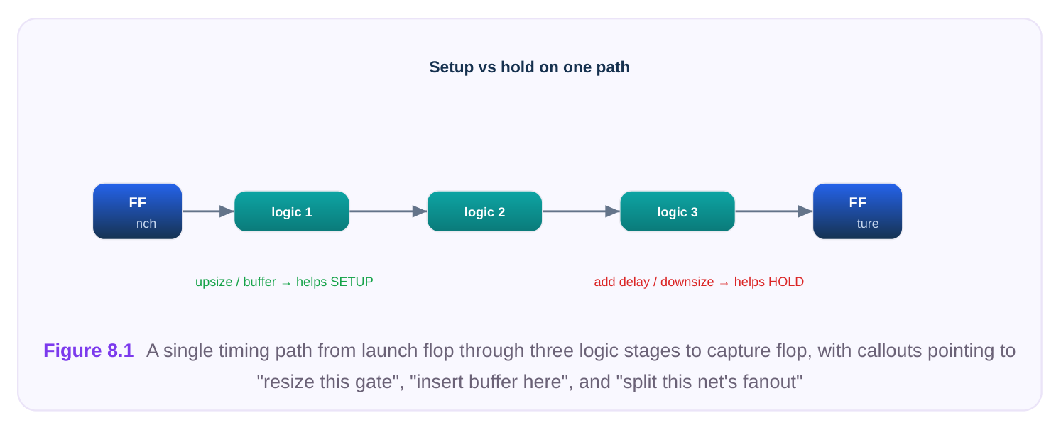
Every standard cell comes in a family of drive strengths. A given logic function — say a two-input NAND — exists as X1, X2, X4, and so on, where the number loosely tracks the width of the output transistors. A stronger (larger) variant can push more current onto its output net, so it charges and discharges load capacitance faster. That is the entire physics of resizing: drive strength versus the cost of carrying it. The cost has two parts. First, a larger cell presents a bigger input capacitance to whatever drives it, so making one gate stronger slows down the previous stage. Second, it consumes more area and leakage, and in a congested region it may not even fit. Upsizing is therefore never free; you are trading the delay of the stage you touched against the delay you just added upstream. Fixing setup by upsizing. When a path is slow (positive required time minus arrival, i.e. negative slack on setup), find the stage that is contributing the most delay — typically a weak gate driving a heavy load — and increase its drive. The stage delay drops because the output transition sharpens. As long as the input-cap penalty on the upstream gate is smaller than the gain, net slack improves. Fixing hold by downsizing. Hold violations are the opposite problem: data arrives at the capture flop too early. The cure is to add delay to the short path. Downsizing a cell, or swapping it for an intentionally weaker variant, slows the stage and pushes the early data later. Downsizing also has the pleasant side effect of reducing input capacitance, which can actually help an upstream setup path — one of the rare cases where two goals align.
THRESHOLD-VOLTAGE SWAPS
Most modern libraries ship the same cell footprint in multiple threshold-voltage (Vt) flavors — commonly a low-Vt (fast, leaky), a standard-Vt, and a high-Vt (slow, low-leakage) version. Because they share the same physical outline and pin locations, swapping between them is the cleanest ECO move available: the cell occupies the exact same site, so placement, routing, and abutment are untouched.
- Low-Vt conducts more strongly at the same voltage, so it is faster but leaks more. Swap to low-Vt to fix setup.
- High-Vt is slower and leaks far less. Swap to high-Vt to fix hold, or to recover leakage on paths with positive slack. A disciplined flow first tries to fix setup with Vt swaps (footprint-preserving) before resorting to drive- strength changes (footprint-changing). For hold, swapping fast cells to a slower Vt on non-critical stages is often the lowest-disturbance fix in the entire toolbox.
# Setup fix: upsize a weak gate and make the previous stage strongersize_cell [get_cells u_alu/g_carry] NAND2_X4size_cell [get_cells u_alu/g_prev] INV_X3# Footprint-preserving speedup: swap a standard-Vt cell to low-Vtswap_vt [get_cells u_alu/g_carry] -to LVT# Hold fix: downsize an over-driven cell so the short path slows downsize_cell [get_cells u_dp/g_fast] BUF_X1swap_vt [get_cells u_dp/g_fast] -to HVT
Lever 2 — Buffer and Inverter Insertion
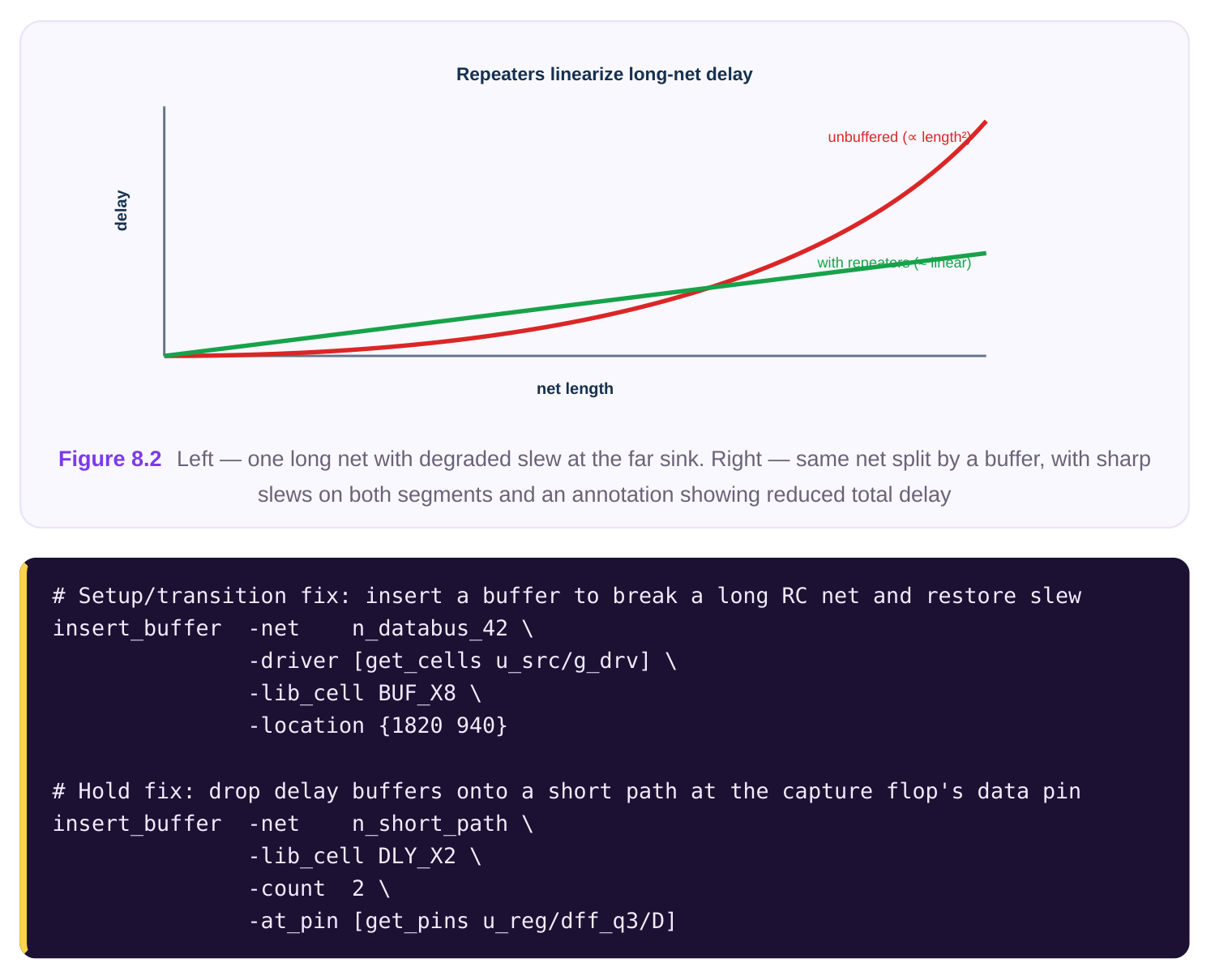
A wire is not free. A long net, or one feeding many sinks, accumulates resistance and capacitance that degrade the signal in two ways: the delay through the wire grows (roughly with the product of R and C), and the slew — the rise/fall transition time — gets sluggish. A slow slew is doubly harmful: it adds delay at the receiving gate and makes timing less predictable. Inserting a buffer (or a pair of inverters) breaks the net into segments. Each segment is shorter, so its RC is smaller, and the buffer regenerates the slew at the midpoint. The classic mental model is that delay over a long wire grows with the square of its length, so splitting one long net into two halves and re-driving in the middle can dramatically reduce total delay — this is repeater insertion. Buffering serves three distinct purposes at ECO:
- 1. Breaking long high-RC nets to cut delay and fix setup on a wire-dominated path.
- 2. Restoring slew / fixing transition violations on a net whose receiver sees a degraded edge.
- 3. Adding intentional delay to fix hold. Here the buffer is a delay element. You drop one or more
buffers (or a dedicated delay cell) onto a short path so data arrives later than the capture clock requires. This is the single most common hold fix in practice. Note the asymmetry between the two delay-buffer uses. To fix setup, a buffer must sit on a net where it relieves more wire/slew delay than it adds in intrinsic cell delay — otherwise you are simply making the path slower. To fix hold, you want to add delay, so any cheap buffer works, and you place it where it touches the fewest other timing paths.
A word of caution on inverter parity: if you insert a single inverter to break a net, you have flipped the logic sense. Buffering must preserve polarity, so use a buffer, a delay cell, or an even number of inverters. Two minimum inverters back-to-back are often faster and smaller than one buffer cell, which is why tools frequently implement a "buffer" as an inverter pair.
Lever 3 — Fanout Optimization
When a single driver feeds too many sinks, every receiver's input capacitance piles onto one net. The driver sees a huge load, its output slew collapses, and delay balloons — and the problem is spread across all the paths through that net, not just one. No amount of upsizing the single driver scales cleanly, because a giant cell has its own large internal delay and presents an enormous input cap to its driver. The fix is structural. Two main moves:
- Driver cloning. Duplicate the driving gate and split the sinks between the two copies, so each driver carries roughly half the load. Cloning is ideal when the sinks are physically spread out: place each clone near its cluster of receivers. Each clone has the same logic function and the same inputs, so it is logically transparent.
- Buffer-tree / fanout balancing. Insert a small tree of buffers between the driver and the sinks, distributing the load across intermediate stages. This is the natural choice when you cannot duplicate the driver (e.g., it has side effects, or the cone feeding it is expensive to replicate). Fanout restructuring is the lever for high-fanout setup paths and slew violations that resizing alone cannot solve. It is heavier than a single resize — it adds cells and changes connectivity — so it is usually a second resort after a Vt swap or upsize proves insufficient.
# Inspect the offending net before actingreport_timing -through [get_nets n_enable] -fanout# Clone the driver and let the tool partition the sinks geographicallyclone_driver [get_cells u_ctl/g_enable] \-fanout_split balanced \-place near_sinks# Or restructure with a balanced buffer tree to a target max-fanoutbalance_fanout -net n_enable -max_fanout 8 -lib_cell BUF_X4
Setup vs Hold: The Core Tension
The hardest part of local fixing is not making a single move — it is understanding that almost every move that helps setup hurts hold, and vice versa. Setup wants data to arrive earlier (faster paths); hold wants data to arrive later (slower paths). They pull in opposite directions on the same physical path. Effect on the data
Move Setup Hold
Upsize a gate / swap to Faster Improves Risks new hold violation
| Downsize a gate / swap | Slower | Risks new setup | Improves |
|---|---|---|---|
| to high-Vt | violation | ||
| Insert buffer on long RC | Usually faster (net | Improves net | May add small hold risk effect) |
| Insert delay buffer on | Slower | Negligible if path has short path | Improves setup slack |
| Clone driver / balance | Faster (lighter fanout | Improves load) | Risks new hold on the lightly- loaded sinks |
This is why the order of operations matters. The conventional discipline is to fix setup first, then fix hold last. Hold fixes add delay and are very local, so they rarely break setup if you leave margin. Setup fixes that speed up paths, by contrast, frequently create hold violations on the now-faster short paths — so you do them before the hold pass and clean up afterward.
Equally important is margining. Never close a fix at exactly zero slack. Process, voltage, and temperature variation, on-chip variation derates, and the small inaccuracies of the ECO estimate all eat into your headroom. Aim for a comfortable positive cushion — and be especially conservative on hold, where there is no frequency knob to save you in silicon: a hold failure is dead silicon, whereas a marginal setup failure can sometimes be recovered by running slower.
Choosing the Lever: A Decision Table
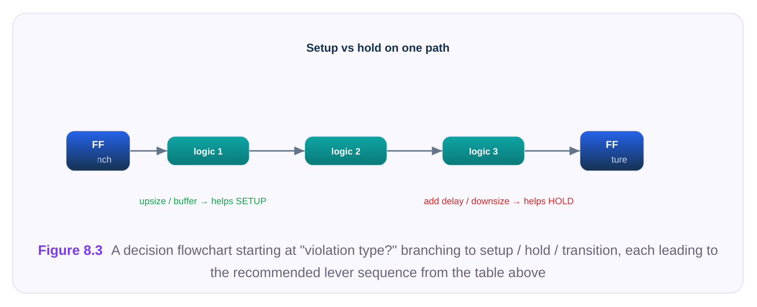
Given a violation, the diagnosis comes first. Look at what is dominating the failing stage — cell delay, wire delay, slew, or fanout — then pick the matching lever. Symptom (from the timing
Likely root cause First lever to try Fallback
Setup fail, weak gate driving Insufficient drive Swap to low-Vt Upsize cell
Setup fail, long net dominates High wire RC Insert buffer (split net) Reroute / shorten net
| Setup fail, one driver feeds many | High fanout | Clone driver / balance | Buffer tree |
|---|---|---|---|
| sinks | fanout | ||
| Transition (slew) violation | Degraded edge | Insert buffer to | Upsize driver |
regenerate slew
Hold fail, short combinational path Data too early Insert delay buffers Downsize / swap to
| Hold fail on many parallel short | Systematic early | Swap stages to high-Vt | Distributed delay cells |
|---|---|---|---|
| paths | data | ||
| Positive slack but high leakage | Over-margined | Swap to high-Vt | Downsize |
cells The guiding principle is least disturbance first: a Vt swap touches nothing but the cell mask layers; a resize may change the cell footprint; buffer insertion and cloning change connectivity and need placement and routing. Start with the lightest move that the physics permits.
Doing It as an ECO
A local timing fix is only as good as its containment. The whole point of an ECO is that you change a few cells and nothing else moves. Several practices keep it that way. Minimal disturbance. Touch the smallest set of cells that fixes the path. Prefer footprint-preserving moves (Vt swaps, equal-size variants) so legalization stays trivial. When you must add cells, place them precisely where the fix needs them — at the failing pin for a hold buffer, near the sink cluster for a clone — so the tool does not ripple placement outward. Reuse spare cells if the change must be metal-only. Late in a project, a respin may be restricted to metal layers only — base layers (transistors) are frozen because new masks for them are ruinously expensive. In that regime you cannot place a brand-new cell; instead you map your fix onto pre- placed spare cells scattered across the floorplan during the original build. The ECO then becomes a rewiring exercise on metal: tie a spare buffer or inverter into the net, hook up its inputs and outputs, and ground the unused spares. Functional-eco and freeze-silicon flows depend on having enough spares of the right types in the right places, which is why teams sprinkle spares generously up front. Re-time locally and verify. After each move, re-analyze the affected paths — and their neighbors — rather than trusting the global picture. A buffer you added for hold may have nudged a parallel setup path; a clone may have created a new hold violation on the lightly loaded branch. Always re-run
report_timing on both setup and hold for the touched region before declaring victory, and confirmyou did not push a new transition or capacitance violation onto an adjacent net.
# After applying fixes, re-time the touched region for BOTH checks
report_timing -from [get_cells u_alu/g_carry] -delay_type max -nworst 5
report_timing -to   [get_pins  u_reg/dff_q3/D] -delay_type min -nworst 5
# Metal-only flow: bind the fix to a pre-placed spare instead of adding a cell
size_cell  [get_cells spare/buf_inst_137] BUF_X4
# (the spare is then rewired into the target net via ECO routing)
Interview Q&A
hold. Explain what happened and how you would resolve it. Upsizing sped up the stage, which helped the setup path but also made a shorter path through that same gate arrive even earlier at its capture flop, breaking hold. The two checks share the physical path and pull in opposite directions. The fix is to leave the setup upsize in place and add delay on the now-failing short path — typically a delay buffer at the capture flop's data pin, or a high-Vt swap on a non-critical stage of that short path. This is exactly why the standard discipline is to fix setup first and clean up hold afterward.
constraint that makes Vt swaps attractive at ECO? A Vt swap is preferred whenever the same footprint exists in a faster or slower flavor, because it preserves the cell's physical outline and pin locations — placement, abutment, and routing are untouched, making it the least-disturbing move available. A drive-strength change usually alters the footprint, which can force legalization and rerouting and may not fit in a congested region. The constraint is leakage and library coverage: low-Vt buys speed at a leakage cost, high-Vt saves leakage at a speed cost, and you can only swap if the needed Vt variant of that exact cell exists.
poor fix, and what would you do instead? A single driver, no matter how large, still presents one lumped load equal to the sum of 40 input caps plus a long, branchy net; upsizing it has diminishing returns and the giant cell adds large input cap upstream and its own internal delay. The structural fix is to reduce the load each driver sees: clone the driver and split the 40 sinks between the copies (placing each clone near its sink cluster), or insert a balanced buffer tree to a sane max-fanout. That cuts both the delay and the slew because every stage now drives a fraction of the original load.
you implement it, and what determines whether you can? In a metal-only window the base/ transistor layers are frozen, so you cannot place a new cell. You implement the buffer by binding the fix to a pre-placed spare cell of the right type near the failing pin, then rewiring it into the net using only metal-layer ECO routing — tying its input and output into the path and grounding any unused spares. Whether this is possible depends entirely on spare-cell planning done at original build time: enough spares, of the right flavors, distributed densely enough that one sits near every likely fix site. If no suitable spare is nearby, the metal-only fix is infeasible and the change must wait for a full respin.
Key Takeaways
- The three everyday local levers are cell resizing (including Vt swaps), buffer/inverter insertion, and fanout restructuring — almost every manual timing fix is a combination of these.
- Resizing trades drive strength against input capacitance and area; upsize or go low-Vt for setup, downsize or go high-Vt for hold.
- Buffers serve three jobs: breaking high-RC nets, restoring slew, and adding intentional delay for hold. Watch inverter parity — use buffers or even inverter counts.
- High-fanout problems are structural; clone the driver or balance the fanout rather than endlessly upsizing one gate.
- Setup and hold pull in opposite directions on the same path. Fix setup first, fix hold last, and always close with positive margin — especially on hold, where silicon offers no recovery knob.
- Choose the least-disturbing lever that the physics allows; reuse spare cells for metal-only changes, and re-time both checks locally after every move.
Comments
Leave a Reply