 ChipBuddy
← Home
ChipBuddy
← Home
The Constrained / Metal-Only ECO Flow
In Chapter 3 we walked through the unconstrained ECO flow, where the engineer is free to add, delete, resize, and freely re-place any cell, and to let the tools re-route as much of the design as needed. That freedom is a luxury you have early in the project. Once a design approaches or crosses tapeout, that freedom evaporates, and a far more disciplined cousin of the flow takes over: the constrained, or metal-only, ECO. This chapter is dedicated entirely to that flow, because in practice it is the version of ECO that most working physical-design engineers spend the bulk of their late-project lives executing, and it is the version interviewers probe hardest.
What "Metal-Only" Really Means
A modern chip is fabricated as a stack of patterned layers. At the very bottom sit the base layers, also called the front-end-of-line (FEOL) layers, where the actual transistors live: the diffusion (active) regions, the polysilicon gates, the wells, and the first contact layer that ties transistors to the metal world above. Stacked on top are the metal and via layers, the back-end-of-line (BEOL), which form the wiring that interconnects those transistors into useful logic. A metal-only ECO, sometimes phrased as a freeze-base-layers ECO, is a change that is allowed to modify only the metal and via masks. The transistor layers are frozen. You may not add a new
transistor, you may not move a gate, and you may not change the silicon footprint of anything already placed. Every change you make must be expressible purely as a rerouting of wires and vias over a transistor landscape that is fixed in stone. Frozen base layers vs re-spinnable metal M6 M5
| M4 | re-spinnable |
|---|---|
| M3 | (metal/via) |
M2 M1 contact
poly FROZEN diffusion
Figure 4.1 Layer stack cross-section with FEOL base layers shaded "frozen" and BEOL metal/via layers shaded
"editable" This sounds enormously restrictive, and it is. The natural question is: if you cannot add transistors, how do you implement new logic? The answer is the central enabler of the entire flow, and we will get to it shortly. First, let us understand why anyone accepts these constraints.
Why Metal-Only Matters After Tapeout
Mask cost dominates the economics here. A full mask set for an advanced process node is a very large capital expense, with each individual layer's mask (or reticle) contributing to the total. When a silicon bug is found after first tapeout, the program faces a brutal choice: respin or not. The cost and schedule of that respin depend almost entirely on how many masks must be regenerated.
| Respin type | Masks regenerated | Relative cost | Relative schedule |
|---|---|---|---|
| Full base + metal (all-layer) | All masks in the set | Highest | Longest |
| Metal-only (BEOL only) | Only metal and via masks | Substantially lower | Substantially shorter |
| No respin (firmware/test | None | Lowest | Shortest |
workaround) Because the metal and via layers are a minority of the total mask count, and because the expensive, slow-to-pattern base layers are reused unchanged, a metal-only respin can cost a fraction of a full respin and return working silicon weeks sooner. The wafers can even be banked: partially processed wafers that have completed the base layers can be held in inventory, then finished with the corrected metal stack once the fix is ready. That is why, when a late bug surfaces, the very first question a manager asks is, "Can we fix it metal-only?"
The Central Enabler: Pre-Placed Spare and Filler Logic
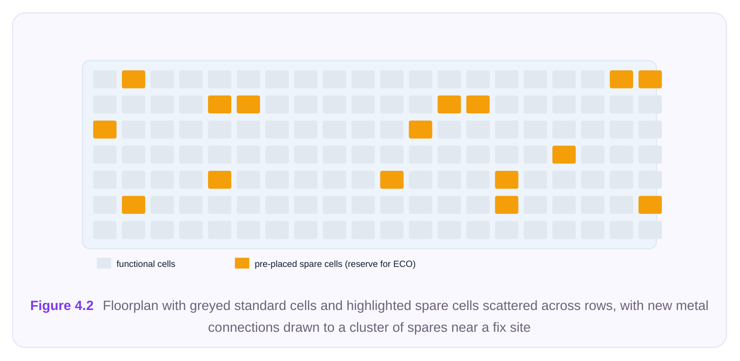
Here is the trick that makes the whole flow possible. Because experienced teams know that late bugs are inevitable, they deliberately scatter unused, fully formed logic cells throughout the layout before tapeout. These are commonly called spare cells (and the related concept of gate-array-style filler- logic cells that can be reconfigured by metal). They are real transistors, already placed, already powered, already legal in the floorplan, but with their inputs tied off to a safe constant and their outputs left unused. They do nothing in the shipping design; they are insurance. A spare-cell strategy typically seeds a mix of cell types distributed across the die:
| Spare cell category | Typical examples | Why included |
|---|---|---|
| Universal gates | NAND, NOR, inverter | Any Boolean function can be built from these |
| Storage | flip-flops, latches | To fix sequential bugs without new base layers |
| Drive variety | several drive strengths each | To meet load and timing at the fix site |
| Combinational mux/AOI | mux, and-or-invert | Reduce gate count for common fix shapes |
Because the spare transistors already exist on frozen base layers, connecting them into the live netlist requires only metal and vias, which is exactly what a metal-only ECO is permitted to touch. The ECO does not create logic; it repurposes logic that was pre-deployed for this exact contingency. When you hear that a fix was "implemented on spares," this is what happened: the engineer reached into the pool of pre-placed insurance cells and wired up the ones needed. How many spares, and of what mix, is itself an engineering judgment made long before any bug exists. Seed too few and a late fix can find no usable inventory near the bug, forcing a full respin you were trying to avoid. Seed too many and you waste die area, leakage power, and routing resource on cells that may never be used. A common practice is to distribute spares roughly uniformly so that every region of the die has some local inventory, then add extra density around blocks that are functionally risky, newly designed, or specification-volatile. The spare distribution is, in effect, a bet on where future surprises will land. There is also a distinction worth drawing. Discrete spare cells are complete, fixed-function gates (a NAND, a flop) that you connect or leave dormant. Filler-style configurable logic, by contrast, is a regular fabric of transistors whose function is determined by the metal pattern laid over it, so a single tile can become several different gates depending on how the metal personalizes it. Configurable fabric trades a little area efficiency for far greater flexibility in what function a given site can deliver.
The Constrained ECO Loop
The metal-only loop mirrors the general ECO loop from Chapter 3, but every step is bounded by the frozen-base constraint.
- 1. Derive the logical fix. Determine the minimal netlist change that corrects the bug. As always,
smaller is safer. In the constrained flow there is added pressure to keep the fix tiny, because every gate you need must be found among nearby spares.
- 2. Map new logic onto available spare cells. Instead of instantiating fresh cells, you bind each gate
of your logical fix to a specific spare instance of a compatible type. No new base geometry is created; you are claiming existing silicon.
- 3. Rewire using metal and vias. Detach the chosen spares' tie-offs, connect their inputs and outputs
into the netlist per the fix, and let the router complete the connections on metal/via layers only. Existing signal routes may be ripped and re-laid, but only above the frozen base.
- 4. Re-verify. Run the same battery as any ECO, plus checks unique to this flow: confirm that only
metal/via masks changed, that no base layer was disturbed, and that every spare you touched was correctly claimed and the ones you did not remain safely tied off. A simplified command sketch of the mapping-and-connect phase, using generic command names, looks like this.
# Read the post-tapeout, frozen design as the starting point
read_design  -frozen_base  ./db/signoff_routed
# Identify the spare cells available near the fix region
report_spare_cells -region {1200 800 1600 1100} \
-types  {NAND2 INV FF} \
-status unused
# Bind the logical fix onto specific spare instances (no new base geometry)
eco_map_to_spare -fix_netlist ./eco/fix_logic.v \
-reuse_spares true \
-allow_new_base_cells false
Once the gates are claimed, the connect-and-reroute phase is constrained to BEOL layers.
# Restrict all routing changes to metal/via masks only
set_eco_constraint -change_layers   {metal via} \
-freeze_layers   {diffusion poly contact} \
-allow_cell_move false
# Detach spare tie-offs, wire in the fix, and reroute on metal only
eco_connect_spares  -fix_netlist ./eco/fix_logic.v
eco_route          -metal_only true -honor_frozen_base true
# Verify nothing below metal moved
verify_metal_only_eco -report ./reports/metal_only_check.rpt
The -allow_new_base_cells false and -freeze_layers settings are the guardrails that make this flow honest: they cause the tools to refuse any operation that would require a new transistor or a baselayer edit, surfacing the violation rather than silently producing an illegal change. A subtlety often missed by newcomers is that "metal-only" does not mean "only adding metal." You are frequently removing and re-laying existing metal too. To route a fix to a distant spare you may need to rip up signal segments that are in the way, push neighboring nets aside, and reconnect everything, all still on the BEOL layers. The frozen-base rule is about the transistors below, not about leaving the existing wiring untouched. This is why metal-only fixes can still introduce new timing, crosstalk, or signal-integrity problems even though no transistor moved: the wiring environment around the change genuinely changed. Keeping the logical intent separate from the physical spare binding is good discipline: the same logical fix can be re-bound onto a different spare if the first choice turns out to be unroutable or timing-poor, without re-deriving the logic from scratch.
Constraints and Gotchas
The metal-only flow is conceptually simple but operationally treacherous. The difficulties almost all stem from the fact that you are working with a fixed, finite, pre-positioned resource pool.
- Right type, right place. It is not enough to find a spare; you need a spare of the right cell type (or one that can serve the function) close enough to the fix site that the metal connection is routable and meets timing. A perfect NAND2 spare on the opposite corner of the die is useless if the route would blow your slack or cannot be physically completed through congestion.
- Footprint and equivalent-cell matching. When you swap or repurpose a cell, the replacement must occupy a compatible footprint and present compatible pin geometry, because the base layers are frozen and cannot shift to accommodate a different cell outline. This is why teams favor families of footprint-equivalent spares.
- Finite resources. The spare pool is a budget. Each fix consumes spares, and there is no replenishing them without a new base layer, which would defeat the entire purpose. Multiple late bugs compete for the same limited inventory, so engineers must spend spares thoughtfully and reserve some headroom for the next surprise.
- Placement is fixed. You cannot nudge a congested region open or move an obstacle aside. If the only nearby spare is hemmed in by dense routing, you may be forced to a more distant spare and accept the timing penalty, or to a more creative logical decomposition that fits the spares you actually have.
- Tie-off hygiene. Spares not used must remain properly tied off, and spares you do claim must have their tie-offs cleanly removed. Leaving a floating input or a half-connected spare is a classic, hard-to-catch metal-only bug.
- Power and clock reach. A spare flip-flop is only useful if a suitable clock is routable to it on metal. Sequential fixes are therefore much harder than combinational ones, which is why teams seed spare flops generously and place them near clock resources.
Contrast With the Unconstrained Flow
It is worth making the comparison from Chapter 3 explicit, because interviewers love to ask exactly where the two flows diverge.
| Dimension | Unconstrained ECO (Ch. 3) | Constrained / metal-only ECO (Ch. 4) |
|---|---|---|
| Base layers | May change freely | Frozen |
| New cells | Instantiated as needed | Only pre-placed spares reused |
| Placement | Cells may be added/moved | Fixed; no cell movement |
| Routing | All layers available | Metal/via only |
| Typical timing | Pre-tapeout / early | Post-tapeout / respin |
| Respin cost if taped out | Full mask set | Metal masks only |
| Main limiter | Engineering effort | Spare availability and location |
The mental shift is this: in the unconstrained flow your design space is "anything the library and floorplan can hold," and the cost of a change is mostly your time. In the constrained flow your design space shrinks to "whatever I can build from the spares that happen to sit near the bug," and the cost of a change is measured in irreplaceable physical resources. The unconstrained flow optimizes for a clean result; the constrained flow optimizes for never touching a base mask.
Interview Q&A
new wafers? Because cost and schedule track the number of masks regenerated and the amount of wafer processing repeated. A metal-only change reuses the frozen, expensive-to-pattern base layers entirely and regenerates only the metal and via masks, which are a minority of the set. Partially processed wafers can even be banked at the base-complete stage and finished with corrected metal once the fix is ready, saving both money and the long base-layer fabrication time.
You don't create new transistors; you repurpose pre-placed spare cells that were deliberately scattered across the layout before tapeout. Those spares are real, already-placed gates with tied-off, unused I/ O. The ECO claims spares of the right type near the fix site, removes their tie-offs, and wires them into the netlist using only metal and vias, which is exactly what the flow is permitted to modify.
must be of the right functional type (or able to serve the function with footprint-equivalent characteristics), it must be physically close enough that the metal connection is routable through local congestion, and the resulting route must still meet timing and load requirements. A correctly typed spare that is too far away or boxed in by dense routing is effectively unusable.
unconstrained one? Spare availability and location. In the unconstrained flow you instantiate whatever you need; in the constrained flow you are limited to a finite, fixed pool that cannot be replenished without a base-layer change. If the right spare type isn't near the bug, or if the pool is
already depleted by earlier fixes, you may be forced into worse timing, awkward logical decompositions, or, in the worst case, an unavoidable full respin.
Key Takeaways
- Metal-only / freeze-base-layers ECO changes only the metal and via masks; the transistor (base) layers are frozen and cannot be moved, added, or modified.
- It matters because a metal-only respin is dramatically cheaper and faster than a full mask-set respin, since the costly base layers are reused and wafers can be banked at the base-complete stage.
- The flow is enabled by pre-placed spare and filler-logic cells, scattered across the layout before tapeout as deliberate insurance; the ECO repurposes them rather than creating new silicon.
- The loop is: derive the minimal fix, map it onto nearby spares of the right type, rewire on metal/vias only, then re-verify that nothing below metal changed.
- The dominant constraints are finding the right spare type close enough, footprint/equivalent- cell matching, a finite non-replenishable spare pool, fixed placement, and clean tie-off
hygiene.
- Compared with the unconstrained flow of Chapter 3, the constrained flow trades engineering freedom for the ability to never touch a base mask, making spare availability, not engineer time, the true limiting resource.
Comments
Leave a Reply