 ChipBuddy
← Home
ChipBuddy
← Home
Spare Cells: Provisioning for Future ECOs
When a chip comes back from the fab with a functional bug, the cheapest possible fix is one that touches only the upper metal layers and vias — the so-called metal-only or ECO mask set. The reason is purely economic: the transistor-forming base layers (diffusion, poly, contact) are the most expensive masks in a modern mask set, and re-spinning them means a full new wafer lot and weeks of turnaround. A metal-only fix re-uses every base-layer mask you already paid for. But there is a catch that defines this entire chapter: you cannot add a transistor that does not already exist in silicon. If your bug fix needs a NAND gate that was never fabricated, no amount of metal rewiring will conjure it into being. Spare cells are the answer to that constraint. They are functional logic gates — real transistors, fully placed and connected to power and ground — that you deliberately scatter across the die before tapeout, even though the design does not use them. They sit dormant, drawing no switching power, waiting. When a post-silicon bug appears, the ECO engineer rewires existing signals through these pre-placed gates using only metal and vias. The spare cells are the raw building blocks; metal routing is the assembly. This chapter explains what spare cells are, why they must be provisioned ahead of time, the three strategies for placing them, how to choose the mix and distribution, and the critical detail that trips up many engineers: tying off unused spares so they neither float nor burn power.
Why Provision Before Tapeout
The logic is unavoidable and worth stating plainly in an interview. After tapeout, the base layers are frozen. A metal-only ECO can:
- Cut existing nets (by removing or rerouting metal).
- Create new connections between any two pins that already exist in silicon.
- Insert or remove buffers/inverters/logic — but only from cells that are already placed and
powered. A metal-only ECO can not:
- Add a new standard cell at the base layer.
- Move an existing functional cell.
- Change a cell's drive strength to a variant that isn't physically present. Frozen base layers vs re-spinnable metal M6 M5 M4 re-spinnable M3 (metal/via) M2 M1 contact poly FROZEN (transistors) diffusion Figure 6.1 Cross-section showing frozen base layers vs. re-spinnable metal/via layers, with a spare cell sitting on base layers and an ECO wire connecting it on metal So the spare-cell question is really a forecasting question: what kinds of fixes might I need, and how many? You are buying an insurance policy in silicon area. Provision too few and a critical bug becomes un-fixable in metal, forcing a costly base re-spin. Provision too many and you waste die area and leakage power on gates you never use. Mature design teams treat spare provisioning as a deliberate budget line, often expressed as a percentage of total cell area.
Strategy 1 — Manual Instantiation
The most controlled approach is to add spare cells explicitly in the RTL or netlist as named instances, then let the place-and-route flow treat them as ordinary cells that simply happen to have no useful connections. Because you name them, you know exactly what type each spare is and (after placement) where it lives. A common pattern is to instantiate spares in banks — small clusters grouped together — so that a future ECO near a given region has a known reservoir of gates to draw from. Banks are easy to track, easy to report on, and easy to reason about during an ECO.
# Manual spare bank: instantiate named spares in the netlist/floorplan
# A mix grouped under a hierarchical bank name for easy tracking
create_spare_bank -name spare_bank_core_a \
-cells { INVx1 INVx4 BUFx2 NAND2x1 NOR2x1 DFFx1 } \
-count_each 4
# Anchor the bank near a region you expect may need future fixes
place_spare_bank -name spare_bank_core_a \
-region { 1200 1800 1450 2050 }
The strength of manual instantiation is total control: you decide the exact recipe and the exact location, which is invaluable when you already suspect which block is riskiest (a late-arriving IP, an unproven interface, a tricky state machine). The weakness is effort and uniformity — placing dozens of banks by hand across a large die is tedious, and it is easy to leave coverage gaps in regions you didn't think about. Because the spares are named instances, they survive verification naturally and can be reported by name at any stage. That traceability is the quiet advantage of the manual approach: when an ECO engineer later asks "what spares do I have in this corner of the block?", a named-bank scheme answers instantly — especially with a consistent naming convention that encodes each bank's region and contents into the instance prefix.
Strategy 2 — Automatic Insertion
The opposite philosophy is to let the implementation tool sprinkle spares automatically. You specify a recipe — a set of cell types and either a target percentage of area or an absolute count — and the tool distributes them as uniformly as the floorplan allows, filling gaps in the placement.
# Automatic insertion: define a spare recipe as a percentage of cell area
define_spare_recipe \
-types   { INVx2 BUFx2 NAND2x1 NOR2x1 MUX2x1 DFFx1 } \
-ratio   { 25    20    20      20      10     5    } \
-target_area_percent 1.5
# Distribute uniformly across the core, honoring a minimum pitch
insert_spare_cells \
-recipe   default \
-distribution uniform \
-min_spacing 30 \
-avoid_blockages true
Automatic insertion guarantees broad, even coverage so that wherever a bug surfaces, a spare is probably nearby. This locality matters enormously, because an ECO buffer is useful only if it is close enough to the net being fixed that the connecting metal does not itself create a new timing or congestion problem. The trade-off is less precision: the tool's idea of "uniform" may not match where your real risk lives, and it may consume area in regions that will never need a fix. Many teams combine both — automatic insertion for baseline coverage plus manual banks in high-risk blocks.
Timing matters here too. Insert spares too early and later optimization may shuffle the floorplan around them; insert too late and the placement may already be too dense to fit them cleanly without legalization disruption. A common compromise is to reserve the area budget up front (so the rest of the placement plans around it) but commit the spares to specific legal sites after the design has largely converged, then re-run a light legalization pass. The goal is for the spares to be present, powered, and legal in the final database without having distorted the functional placement that surrounds them.
Strategy 3 — Programmable / Configurable Spare Logic
A third, more flexible style uses gate-array-like spare cells whose final function is determined entirely by metal. The base layers lay down a generic array of transistors (and sometimes fixed local connections), but the cell's personality — whether it becomes an inverter, a NAND, a NOR, a latch — is decided by which metal/via pattern you drop on top during the ECO.
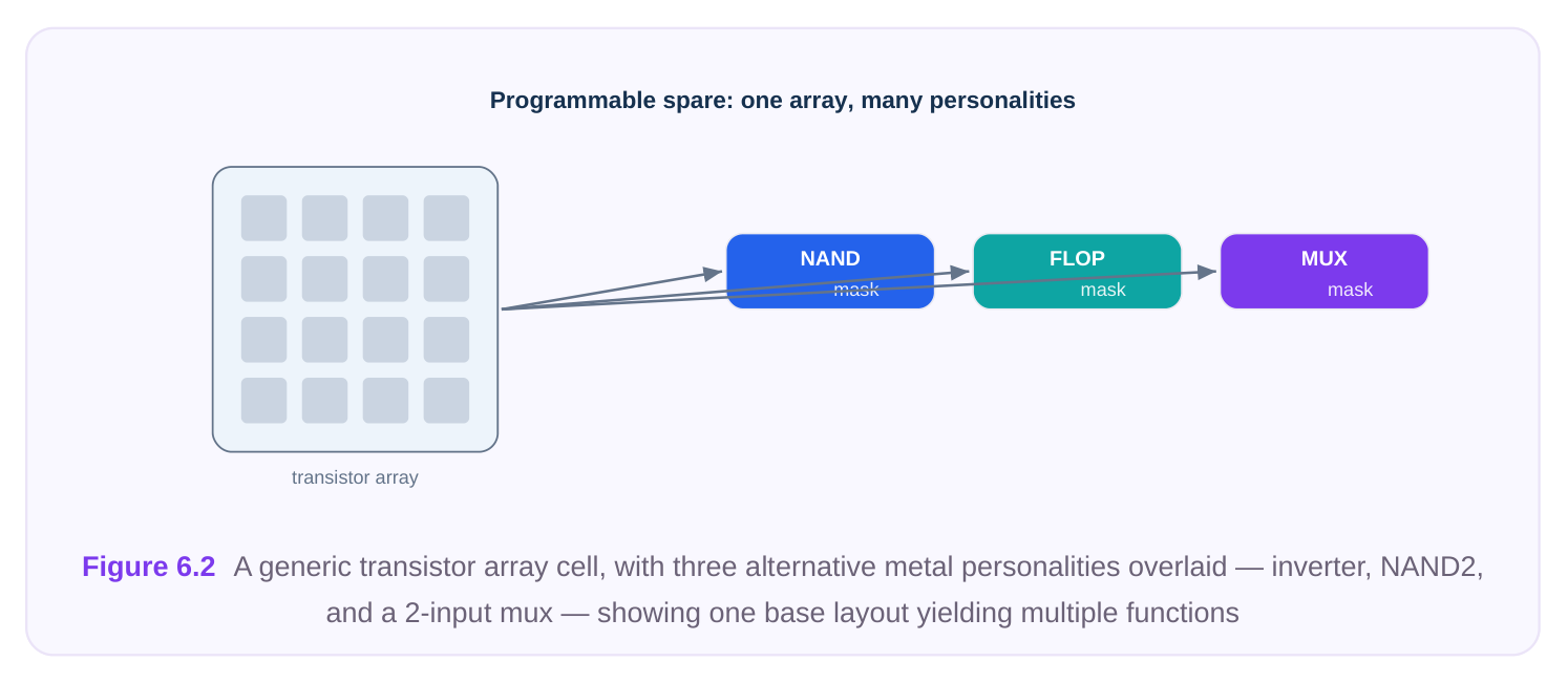
The appeal is density of optionality: a single pool of programmable cells can satisfy a wide variety of fixes, so you don't have to guess the exact gate-type mix in advance. The cost is that these cells are typically less area- and timing-efficient than a purpose-built standard cell of the same function, and the ECO flow must understand how to "program" them with the right metal pattern. They shine in designs where the nature of future fixes is highly uncertain. In practice, programmable arrays and conventional spares are not mutually exclusive. A robust scheme often layers all three strategies: automatic insertion lays down a uniform baseline of common gates, manual banks reinforce the blocks most likely to need late fixes, and a sprinkling of programmable cells acts as a wildcard for the functions nobody anticipated. The art is in not doublepaying — you do not want three overlapping reservoirs all consuming area in the same low-risk corner while a genuinely risky block goes under-served.
Choosing the Spare Mix
There is no universal recipe, but a few principles guide a sensible mix.
Typical share of
Spare type Why include it
| Inverters (multiple | The workhorse of metal ECOs — polarity fixes, signal | High |
|---|---|---|
| drives) | regeneration, simple buffering | |
| Buffers (multiple | Repair long ECO routes, fix hold/transition after rewiring | High |
drives)
2-input NAND / NOR Universal gates; almost any combinational fix can be built Medium–high
| 2:1 multiplexers | Insert select/bypass logic, swap a signal source | Medium |
|---|---|---|
| Flip-flops | Add pipeline stages or capture/observe points; relatively rare | Low |
but high-value
Programmable array Catch-all for unforeseen logic Optional Key reasoning to articulate in an interview:
- Favor universal gates. NAND, NOR, and inverters can compose nearly any combinational function, so a pool weighted toward them maximizes flexibility per area.
- Include several drive strengths. A fix near a heavily loaded net needs a stronger buffer; one in a quiet corner needs only a small inverter. Stocking only one drive forces compromises.
- Spare flops are expensive but precious. Sequential bugs are harder to fix in metal, and a flop already placed and clocked can be the difference between a metal fix and a re-spin. Most teams keep a modest count, often pre-connected to a nearby clock to ease later use.
- Distribution beats raw count. A thousand spares clustered in one corner are nearly useless for a bug on the far side of the die. Spatial spread — locality — is what makes the pool effective. The headline trade-off is summarized below. More spares Fewer spares Higher chance any bug is fixable in metal Lower area and leakage overhead Better locality, shorter ECO routes Less wasted silicon on unused gates Greater confidence to avoid a base re-spin Risk that a fix has no nearby building block More leakage power to tie off Tighter, denser layout A typical starting point is on the order of 1–3% of cell area, tuned by design maturity and risk tolerance: a brand-new, aggressive design warrants more; a proven, low-risk derivative warrants less.
Tying Off Spares So They Don't Float or Burn Power
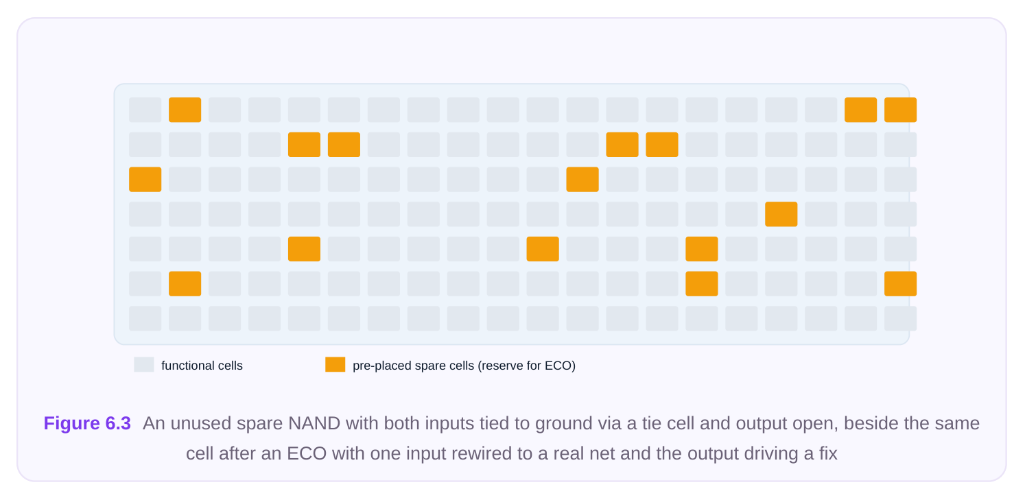
This is the detail interviewers love, because a mis-handled spare cell can cause real silicon problems. An unused gate is not "free" by default. If its inputs are left floating, the input transistors can sit in their linear region and conduct a continuous crowbar current from supply to ground — wasting static power and, in extreme cases, causing reliability or electromigration concerns. Floating inputs are also undefined for analysis tools. The rule is simple: every input pin of an unused spare must be driven to a fixed logic level — tied to power or ground through the appropriate tie cell (or via a tie-off that the methodology specifies), never left dangling. The output of an unused spare is left unconnected, which is fine because nothing reads it.
# Tie off all unused spare inputs to a known level; leave outputs open
foreach_in_collection inst [get_cells -filter "is_spare == true"] {
set_attribute $inst spare_status unused
# Drive every input pin to a constant via tie cells
tie_unused_pins -cells $inst -tie_high_cell TIEHIx1 \
-tie_low_cell  TIELOx1 \
-prefer low
}
# Verify: no spare input should be left floating after tie-off
report_floating_pins -only_cells [get_cells -filter "is_spare == true"]
A few practical points:
- Choose the tie level to minimize leakage. For a given gate, one input polarity may put the cell in a lower-leakage state than the other; methodologies often default unused inputs to the quieter level.
- Connect supplies properly. A spare cell must be on the power grid — its VDD/VSS rails abutted and connected exactly like a functional cell — or it cannot be used later. A spare that was never powered is dead weight.
- In multi-supply designs, mind the domain. A spare only helps fix logic in the same power domain it belongs to. Provision spares per domain, and ensure each is tied off and powered within its own domain so it is not stranded behind a switched-off rail.
- Tie-offs are reversible in metal. During an ECO, you remove the tie connection on the input you need, route your real signal in, and connect the output — all in metal. That reversibility is the whole point.
Interview Q&A
base layers — diffusion, poly, contact — that form transistors are frozen at tapeout. A metal-only ECO re-spins only upper metal and via masks to save cost and time, so it can rewire and reconnect existing transistors but cannot create new ones. Any gate the fix needs must already be present as a placed, powered spare. That constraint is the entire reason spares are provisioned in advance.
What's the problem, and how do you avoid it? The fix would require a very long ECO route, which can introduce new timing violations (delay, transition), worsen congestion, and consume scarce uppermetal resources. You avoid it by prioritizing distribution over raw count when provisioning — spreading spares uniformly (automatic insertion) and reinforcing high-risk blocks with manual banks — so that a usable building block is always near any likely fix site. Locality, not just quantity, makes a spare pool effective.
input can leave the input stage partially conducting, creating a static crowbar current that wastes power and is undefined for analysis. Tying every unused input to a fixed level through a tie cell eliminates that. The chosen level is typically the one that puts the cell in its lowest-leakage state for that gate type; the output is left open because nothing reads it. During an ECO you remove the tie on the needed input and route the real signal in.
proven derivative? For the aggressive design I'd budget more area (toward the higher end, perhaps a few percent), weight the mix toward universal gates (inverters, buffers, NAND/NOR across several drive strengths), include a modest count of pre-clocked flops for sequential fixes, and possibly add programmable array cells to cover unforeseen logic. For the proven derivative I'd cut the budget, since fewer late bugs are expected, and lean on a leaner inverter/buffer/NAND pool. In both cases I'd ensure even distribution and per-domain provisioning rather than just hitting a count target.
Key Takeaways
- Spare cells are real, powered logic gates placed before tapeout so that future bugs can be fixed with cheap metal-only ECOs instead of expensive base-layer re-spins.
- You provision them in advance because base layers freeze at tapeout — you can rewire existing transistors but never create new ones.
- Three provisioning strategies: manual instantiation (named banks, full control), automatic insertion (tool sprinkles a configured mix for uniform coverage), and programmable array cells (one base layout, many metal-defined functions).
- Choose a mix weighted toward universal gates and multiple drive strengths, include a few precious spare flops, and treat spatial distribution as more important than raw count.
- Always tie off unused spare inputs to a fixed level to prevent floating-input leakage, and ensure every spare is on the power grid within its own power domain.
- The core trade-off is area and leakage overhead versus ECO flexibility and the confidence to avoid a re-spin — typically tuned to roughly 1–3% of cell area based on design risk.
Comments
Leave a Reply