 ChipBuddy
← Home
ChipBuddy
← Home
Prerequisites & Setup for Optimization
Chapter 2 — Prerequisites & Setup for Timing Optimization
An optimizer is only as honest as the environment you hand it. It does not "know" your design intent; it knows the constraints, the timing graph, the library data, and the placement/routing state you give it. If any of those is wrong, the tool will dutifully optimize toward the wrong target — burning runtime, spending area and leakage, and possibly making real silicon worse. This chapter is about everything that must be true before you trust a single number an optimizer reports. Treat it as the pre-flight checklist that separates engineers who close timing from engineers who chase ghosts. The recurring theme: garbage in, confident garbage out. Optimization amplifies the quality of your setup. A clean setup makes a mediocre tool look good; a dirty setup makes an excellent tool look incompetent.
Why Setup Determines Trust
When you ask "is this path's slack real?", you are implicitly asking four sub-questions:
- 1. Does a clock with the right period, edges, and uncertainty actually reach both launch and capture
registers?
- 2. Are the start- and end-point arrival/required times anchored correctly to the outside world (I/O
delays) or to internal references?
- 3. Have you told the tool which paths are not real (false paths) or have relaxed requirements
(multicycle paths)?
- 4. Is the delay data (cell, net, derate) characterized for the operating condition you are analyzing?
If you cannot answer "yes" to all four, the slack number is an opinion, not a fact. Optimization built on an opinion produces fixes that may evaporate at signoff. Realizing intent: PM-cell insertion
| Power intent | Match library | Insert & place | Tie controls & | Re-verify |
|---|---|---|---|---|
| (strategies) | PM cells | cells | supplies |
Figure 2.1 Funnel showing RTL/netlist + SDC + libraries + DEF flowing into "Timing Graph" → "Trustworthy Slack"
gate → Optimizer
Constraint Completeness and Hygiene
Constraints are the contract between you and the optimizer. Three categories dominate, and each has a characteristic failure mode. Clocks. Every sequential element must be reached by a defined clock. Undefined or partially defined clocks create unclocked registers, which the tool may treat as having no timing requirement — so it ignores genuinely critical logic. Generated clocks (dividers, gated clocks) must be derived from their master so that ratios and edges track correctly. A missing generated-clock definition is one of the most common reasons a path "looks fine" in the tool and fails on the bench. I/O timing. Input and output delays model the logic outside the current block. Omit an input delay and the tool assumes the data is available at time zero — wildly optimistic, so it under-optimizes the input path. Over-specify an output delay and the tool over-optimizes, wasting area and power on a constraint that does not exist. The virtual clock used as the reference for I/O delays must itself be defined and consistent with the interface spec. Timing exceptions. False paths and multicycle paths tell the tool where not to spend effort and where the requirement is relaxed. Their absence and their excess are both dangerous, as the table below makes explicit.
| Exception issue | What the optimizer does wrong | Symptom you'll see |
|---|---|---|
| Missing false path | Optimizes a path that can never be sensitized | Effort wasted; real paths starved; area/ leakage up |
| Missing multicycle path | Tries to close a relaxed path in one cycle | Impossible negative slack; aggressive over-sizing |
| Over-broad false path | Masks a genuinely failing path | Silicon failure despite "clean" timing |
report
| Wrong multicycle | Path closed against wrong required | Marginal hardware; failures at corner |
|---|---|---|
| multiplier | time | extremes |
| Missing case analysis | Inactive logic treated as active | Phantom critical paths through mux |
select trees Case analysis deserves its own mention. Setting constant values on mode pins, scan-enable, or configuration straps prunes the timing graph to the paths that are actually active in a given functional state. Without it, the tool sees paths through test logic or unused mux legs and may "optimize" them at the expense of real ones. A disciplined order of operations when loading constraints: read the netlist, read constraints, then immediately ask the tool to report anything unconstrained before you do anything else.
# illustrative — generic, not tool-specific
read_netlist     ./netlist/top.mapped.v
read_constraints ./constraints/top.sdc
# Surface problems BEFORE optimizing — these checks are non-negotiable
report_unconstrained_endpoints           ;# illustrative — generic, not tool-specific
report_disabled_timing                   ;# illustrative — generic, not tool-specific
check_timing_setup                       ;# illustrative — generic, not tool-specific
The SDC primitives themselves are standardized; how you invoke the checkers varies by tool. Keep that distinction clear:
# standard (SDC)
create_clock        -name CLK -period 2.000 [get_ports clk]
create_generated_clock -name CLK_DIV2 -source [get_ports clk] \
-divide_by 2 [get_pins div_reg/Q]
set_input_delay  0.40 -clock CLK [get_ports data_in*]
set_output_delay 0.35 -clock CLK [get_ports data_out*]
set_clock_uncertainty 0.08 -setup [get_clocks CLK]
set_false_path   -from [get_clocks CLK] -to [get_clocks CLK_ASYNC]
set_multicycle_path 2 -setup -from [get_pins slow_src*/Q] -to [get_pins slow_dst*/D]
set_case_analysis 0 [get_ports scan_enable]
Inputs and the Consequence of Getting Them Wrong
Before optimization, audit each input class against the price of error. This table is the one to internalize for interviews — examiners love asking "what happens if X is missing?"
| Input | If missing or wrong | Net consequence |
|---|---|---|
| Clock definition | Registers unclocked or wrong period | Critical paths invisible or mis-targeted |
| Clock uncertainty / jitter | Margin mis-modeled | Optimistic closure that fails in silicon |
| Input/output delay | Interface arrival mis-anchored | I/O paths over- or under-optimized |
| False/multicycle paths | Phantom or relaxed paths | Wasted effort or hidden real failures |
mishandled
Case analysis Inactive logic seen as active Optimization energy spent on dead
| Library for a corner | Delay data missing/incorrect | Corner not truly analyzed; signoff gap |
|---|---|---|
| Parasitic / RC estimate | Net delay wrong | Wrong path ranking; fixes don't transfer |
| Legal placement/route | Graph doesn't match physical reality | Estimated gains don't materialize |
state Notice that several rows share the same outcome: the ranking of critical paths shifts. Optimizers work hardest on the worst paths they can see. If your inputs reorder that list incorrectly, the tool optimizes the wrong things in the right way.
Libraries and Operating Conditions
Every corner you intend to analyze needs characterized timing (and power) data. A corner is a combination of process, voltage, and temperature, plus an RC interconnect condition. If you ask the tool to close a slow corner but only loaded a typical-corner library, one of two bad things happens: the tool errors out, or worse, it silently substitutes data and reports numbers that mean nothing. For optimization specifically, you generally need: - Slow/late libraries for setup (max-delay) closure — slow process, low voltage, the temperature that worsens delay for your technology. - Fast/early libraries for hold (min-delay) closure — fast process, high voltage, the opposite temperature extreme.
- Power-characterized data (leakage at temperature, internal and switching energy) if you are co- optimizing power. Confirm that cell variants the tool may use during optimization — multiple drive strengths, multiple threshold-voltage flavors, alternate-row-height cells — are all present and not accidentally restricted by a "don't use" list. An optimizer cannot down-size leakage if the low-leakage variants were filtered out before it started.
Multi-Corner Multi-Mode (MCMM) Setup
Real blocks must work across several operating conditions (corners) and in several functional states (modes — e.g., functional, test, low-power). A scenario (sometimes called an analysis view) is the pairing of one mode with one corner plus a check type (setup or hold). The optimizer must satisfy all active scenarios simultaneously; fixing one in isolation can break another, which is why single-corner optimization is a trap.
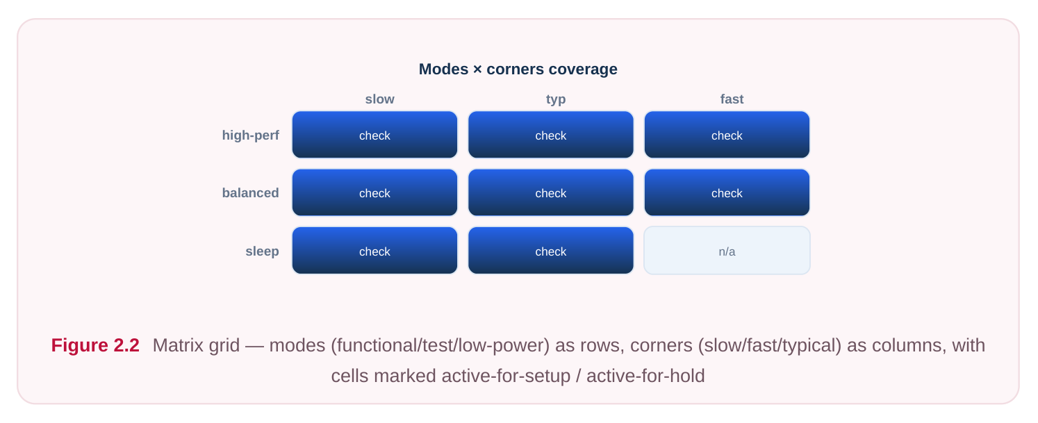
A compact way to plan this is a view table. Below is an illustrative set; your real list depends on the technology and product spec.
| Scenario (mode × corner) | Check | Purpose | Active in opt |
|---|---|---|---|
| Functional × slow-low-V-hot | Setup | Worst max-delay | Yes |
| Functional × fast-high-V-cold | Hold | Worst min-delay | Yes |
| Test × slow-low-V-hot | Setup | Scan-shift timing | Yes |
| Low-power × slow-low-V | Setup | Reduced-voltage closure | Yes |
| Functional × typical | Setup | Reference/QoR tracking | No (report only) |
Mark a scenario active only if you want the optimizer to spend effort on it. Marking everything active maximizes correctness but multiplies runtime and can over-constrain the tool into conservative, powerhungry fixes. A common practice is to optimize against a curated set of dominant scenarios (the ones that historically gate closure) and use the full set for signoff verification.
# illustrative — generic, not tool-specific
create_corner   slow_hot   -lib ./libs/slow_lowV_hot/   -rc ./rc/cmax.tlu
create_corner   fast_cold  -lib ./libs/fast_highV_cold/ -rc ./rc/cmin.tlu
create_mode     func -constraints ./constraints/func.sdc
create_mode     test -constraints ./constraints/scan.sdc
# Pair modes and corners into scenarios, then mark which the optimizer must satisfy
create_scenario func_setup -mode func -corner slow_hot  -check setup
create_scenario func_hold  -mode func -corner fast_cold -check hold
create_scenario test_setup -mode test -corner slow_hot  -check setup
set_active_scenarios {func_setup func_hold test_setup}   ;# optimizer targets these
together
The SDC content inside each mode is standard; the commands that build corners, modes, and probe whether candidates understand that MCMM machinery sits above SDC, not inside it.
Physical State and Clean DRV Baseline
Timing estimated on an illegal or stale physical state is fiction. Before optimizing at a given stage, confirm the design matches the stage's expectations: legal placement (no overlaps, on-site, respecting blockages) for placement-stage optimization, and a routed or route-aware state for post-route optimization where coupling and real RC matter. Optimizing on placement-stage estimates and expecting the numbers to hold after routing is a classic disappointment. Equally important is a clean design rule violation (DRV) baseline: max transition, max capacitance, and max fanout must be under control before you read timing seriously. DRVs distort delay calculation — a slow, overloaded net reports a delay that the tool may "fix" with the wrong move, and once you clean the DRV the path ranking shifts anyway. Fix electrical legality first, then optimize timing, then cooptimize power. Order matters because each stage changes the inputs to the next.
Effort, Targets, and the Baseline Snapshot
Optimizers expose an effort dial that trades runtime for quality of result (QoR). High effort explores more transforms — resizing, buffering, restructuring, layer/threshold swaps — but costs hours. Set effort to match the stage: lower effort during exploratory iterations, higher effort for the closing push. Setting unrealistic targets (asking for zero slack with massive negative WNS, or demanding leakage reduction the library cannot supply) makes the tool churn without converging. Set targets you can defend: a slack target with realistic margin, a total-negative-slack (TNS) goal, a leakage or dynamic-power budget, and area guardrails so timing fixes do not blow the floorplan. Always express targets per active scenario.
Finally, capture a baseline snapshot before you change anything. Without a before-picture you cannot prove the optimizer helped, and you cannot detect regressions in metrics you were not targeting (e.g., hold getting worse while you chase setup).
# illustrative — generic, not tool-specific
set_optimization_effort -level medium                 ;# raise to high for final
closure
set_timing_target -scenario func_setup -wns 0.000 -margin 0.030
# Baseline BEFORE optimizing — record every metric you care about
report_timing  -setup -nworst 50 > baseline_setup.rpt   ;# illustrative
report_timing  -hold  -nworst 50 > baseline_hold.rpt    ;# illustrative
report_drv                        > baseline_drv.rpt    ;# illustrative
report_power                      > baseline_power.rpt   ;# illustrative
Note that report_timing exists in standard flows conceptually, but exact option spelling is tool-
dependent — hence the illustrative tag. The discipline, not the syntax, is what transfers between tools.
A Readiness Checklist
Run this before invoking any optimizer. If any box is unchecked, stop and fix it first.
- [ ] Netlist loads with no missing references or unresolved cells.
- [ ] Every sequential element is reached by a defined clock; generated clocks derived from masters.
- [ ] Clock uncertainty/jitter and any derates applied for each corner.
- [ ] Input and output delays defined against valid (real or virtual) clocks.
- [ ] False paths and multicycle paths reviewed — none missing, none over-broad.
- [ ] Case analysis set for all mode/config/test pins.
- [ ]
report_unconstrained_endpointsand a setup-check report come back clean. - [ ] Libraries present and characterized for every active corner (setup and hold).
- [ ] Cell variants needed for optimization (drive strengths, Vt flavors) not blocked.
- [ ] Corners, modes, and scenarios defined; active scenario list curated and justified.
- [ ] Physical state legal for the stage (placement legal / route-aware as required).
- [ ] DRV baseline clean enough that delay calculation is trustworthy.
- [ ] Effort level and per-scenario targets set realistically.
- [ ] Baseline timing, DRV, and power snapshots saved for before/after comparison.
Interview Q&A
Q1. Why can a missing false path actually make optimization results worse, not just slower? Because the optimizer ranks and attacks the worst paths it can see. A phantom path that can never be sensitized may appear among the worst, so the tool spends transforms — buffering, up-sizing, restructuring — on logic that does not matter, consuming area and leakage budget and starving the
genuinely critical paths. So it is not merely wasted runtime; it actively misallocates effort and can leave real paths under-optimized. Q2. What is the difference between a mode, a corner, and a scenario, and why must scenarios be optimized simultaneously? A corner is a PVT-plus-RC operating condition (the physical environment). A mode is a functional state defined by its own constraints (functional, test, low-power). A scenario pairs one mode with one corner and a check type (setup or hold). They must be optimized together because a fix that helps one scenario can hurt another — up-sizing a cell to close a slowcorner setup path can worsen a fast-corner hold path. Single-scenario optimization produces fixes that unravel at signoff. Q3. You loaded only the typical library but asked the tool to close the slow corner. What's the risk? Best case, the tool errors out because the requested corner data is absent. Worse case, it proceeds with substituted or default data and reports slack that has no relation to the real slow-corner behavior. You would "close" timing in the report and fail in silicon. Setup closure needs slow/late data; hold needs fast/early data — both must be characterized for every active corner. Q4. Why insist on a clean DRV baseline and a legal physical state before trusting slack? Delay calculation depends on transition times, net capacitance, and real RC. Max-transition or max-cap violations distort those inputs, so the reported delay is wrong and the path ranking is wrong. Likewise, timing estimated on an illegal or stale placement does not reflect what routing will produce, so estimated gains evaporate. Cleaning DRVs and legalizing the physical state first ensures the slack you optimize against is the slack you will actually see at the next stage.
Key Takeaways
- Optimization amplifies setup quality: clean inputs make tools look good, dirty inputs make them look broken. Trust nothing until prerequisites are verified.
- Constraint hygiene is the highest-leverage prerequisite — missing clocks, missing I/O delays, and wrong exceptions silently reorder the critical-path list the optimizer works from.
- Distinguish standard SDC (clocks, delays, exceptions, case analysis) from tool-specific MCMM orchestration (corners, modes, scenarios, active-scenario selection).
- Every active corner needs characterized libraries for both setup (slow/late) and hold (fast/early); needed cell variants must not be filtered out.
- Optimize across all active scenarios simultaneously; curate the active set to balance correctness against runtime and over-conservatism.
- Establish a legal physical state and a clean DRV baseline first so delay calculation is trustworthy and gains transfer to the next stage.
- Set realistic, per-scenario targets and an appropriate effort level, and always capture a baseline snapshot so you can prove improvement and catch regressions.
Comments
Leave a Reply