 ChipBuddy
← Home
ChipBuddy
← Home
Post-Route Optimization
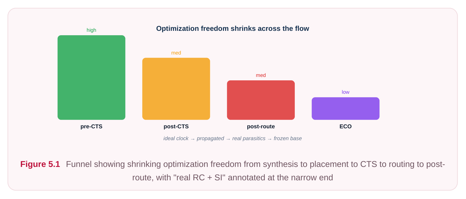
By the time a design reaches post-route optimization, almost every degree of freedom you once enjoyed has quietly closed. The cells are placed, the clock tree is built and balanced, and—most importantly—the signal nets now carry physical wires on real metal layers. This is the most constrained stage of the entire timing-and-power flow, and understanding why it is so constrained is the key to working in it intelligently. In earlier stages you optimized against estimates: a placementbased wire-load guess, or a trial-route approximation of capacitance and resistance. Now the router has committed to actual geometry, a parasitic extractor has read that geometry and produced real RC, and a signal-integrity engine can finally compute crosstalk between physically adjacent wires. The timing you see is, for the first time, close to what silicon will deliver. The flip side is that every edit you make perturbs that physical reality, so each change must be small, locally re-routed, and re-extracted before you can trust the result. This chapter explains what post-route optimization is allowed to fix, what it must never attempt, how to work with real parasitics, and how to converge without unravelling timing you have already closed.
Why this pass exists: estimates versus reality
Every pre-route timing number rests on a prediction of the wire. Placement-stage tools use statistical or Steiner-tree approximations; even a "global route" estimate assumes idealized track usage and ignores detailed via stacks, jogs, and detours around blockages. Reality diverges for several concrete reasons:
- The router takes detours around congestion, dense macros, and routing blockages, so the real wire is often longer than the Steiner estimate.
- Layer assignment matters enormously. A net the estimator assumed would sit on a thick upper metal might be squeezed onto a thin, resistive lower layer, multiplying its delay.
- Via count and via resistance are invisible to most pre-route models but very real after detailed routing.
- Coupling capacitance to neighboring wires—the basis of crosstalk—simply does not exist until wires have neighbors. Because of these gaps, a path that looked comfortably positive pre-route can show a fresh setup violation post-route, and a path that was fine can now suffer a hold problem or a delta-delay bump from an aggressor switching alongside it. Post-route optimization is the pass that reconciles the design with this newly-real physical world.
Working with real parasitics
The currency of this stage is extracted parasitics, usually delivered in a standard parasitic exchange format. The extractor reads the routed database and produces per-net resistance and capacitance— ideally a coupled model that separates ground capacitance from coupling capacitance so the SI engine can reason about aggressors. The discipline that defines a clean post-route flow is incremental extraction: after any physical edit, you do not trust stale RC. You re-extract the affected nets, re-time, and only then judge whether the edit helped.
# illustrative — generic, not tool-specific
# Read routed parasitics and time against them
read_parasitics -format spef ./extracted/top_route.spef
update_timing
report_timing -delay_type max -max_paths 50
report_timing -delay_type min -max_paths 50
The mental model to carry into an interview is simple: measure, edit a little, re-measure. Skipping the re-measure step is the single most common way engineers fool themselves at this stage, because the optimizer's internal delay model and the post-edit extracted reality can drift apart after even a modest change.
What post-route optimization fixes
Three families of problems land on this stage's desk.
- 1. Residual setup and hold violations. These are paths that were close pre-route and tipped over
once real RC arrived, plus any hold issues exposed by the now-accurate clock and data delays. Hold is especially a post-route concern because hold margins are small and very sensitive to the exact delay of short nets.
- 2. Design-rule (electrical) violations. Transition (slew) and capacitance limits that the real wire now
violates—typically long, resistive nets that degrade slew, or high-fanout nets whose total capacitance exceeds the driver's budget.
- 3. Signal-integrity violations. Crosstalk-induced delta delay (an aggressor speeding up or slowing
down a victim, pushing setup or hold over the edge) and crosstalk-induced noise glitches (a quiet victim receiving an injected pulse that could be latched or could violate noise margins). The fixes are surgical and layer-aware. The goal is the smallest physical change that resolves the violation while disturbing the least amount of already-closed timing around it.
The post-route fix menu
| Issue | Typical surgical fix | Governing constraint |
|---|---|---|
| Residual setup | Footprint-preserving upsize of a driver; violation | Setup (data arrival vs required) targeted buffer on a long routed net |
| Residual hold | Insert delay/hold buffers on short paths; | Hold (min path, often set_min_delay / |
| violation | downsize an over-fast driver | library hold checks) |
| Max transition | Upsize driver; split long net with a repeater; violation | set_max_transition promote net to a less resistive layer |
| Max capacitance | Upsize driver; insert buffer to partition violation | set_max_capacitance fanout |
| Crosstalk delta- | Increase victim driver strength; add delay | Setup/hold with SI enabled spacing/shielding; reroute on a quieter |
track
| Crosstalk noise | Spacing, layer change, shielding (ground/ | Noise/glitch margin |
|---|---|---|
| glitch | power adjacency); strengthen victim driver | |
| Antenna or via- | Insert antenna diode; add/repair vias; layer quality issue | Manufacturing/electrical rules hop |
The right-hand column is the discipline that keeps you honest: every fix is tied to the specific constraint it is meant to satisfy, so you can confirm closure with the same checker that flagged the problem.
Allowed transforms now
The defining feature of post-route transforms is that they preserve as much committed geometry as possible.
- Footprint-preserving sizing. Swapping a cell for a higher- or lower-drive variant that occupies the same site footprint and the same pin locations, so the existing routing connects with minimal disturbance. This is the workhorse move.
- Spare-cell and in-place edits. Using pre-placed spare cells or in-place logical swaps to add buffering without opening new placement area.
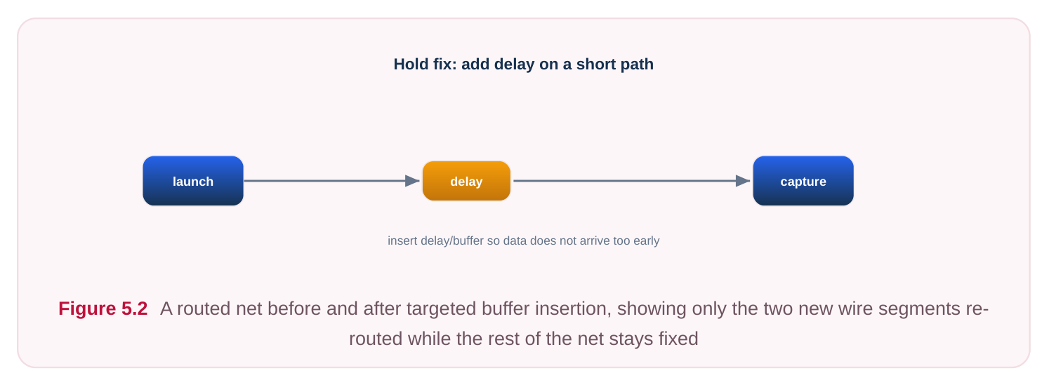
- Targeted buffer insertion on routed nets. Cutting a specific long or violating net and inserting a repeater, then locally re-routing just the two new segments.
- Layer and via fixes. Promoting a critical net to a thicker, less resistive layer; adding redundant vias; fixing via stacks that introduced resistance or reliability issues.
- Shielding and spacing for SI. Inserting grounded shields beside a noisy victim, or nudging the route onto a quieter neighborhood.
Forbidden large restructuring
Equally important is knowing what you cannot do. Anything that would invalidate large amounts of existing routing or the closed clock tree is off the table at this stage:
- No logic re-synthesis or large-scale restructuring of the data path.
- No re-placement of large cell groups or moving cells far from their committed sites.
- No clock-tree restructuring—the tree is balanced and any change ripples through every endpoint's skew.
- No global re-routing that would rip up and re-lay healthy nets. These moves belong to earlier stages. Attempting them here trades a small, known problem for a large, unknown one, and typically destroys timing you have already closed.
Default settings versus aggressive settings
Post-route optimizers ship with conservative defaults precisely because the cost of disturbance is high. You change them deliberately, not reflexively.
| Setting | Default (post-route) | When to go aggressive | Risk of aggressive |
|---|---|---|---|
| Effort / iteration | Moderate, disturbance- count | Stubborn residual setup limited | Longer runtime, more churn near tape-out |
| SI analysis | On, but fixes gated | Real crosstalk failures present | Spacing/shielding consumes tracks |
| Sizing scope | Footprint-preserving only | Critical path needs a non- footprint cell | New placement legalization, reroute |
| Buffering | Targeted, few nets | Many long high-fanout nets | Area/congestion growth |
| Hold fixing | Conservative, leave margin | Aggressive hold violations remain | Over-buffering, leakage and power cost |
| Re-route scope | Local only | Localized congestion blocks | Risk of disturbing neighbors |
a fix The general rule: start with defaults, let the tool make the minimal moves, re-extract, and only widen the aperture for the specific violations that remain. Aggressive settings are a scalpel for the last few stubborn paths, not a blanket policy.
Generic command sketches
A typical post-route optimization invocation asks the tool to fix timing and design-rule problems while honoring the disturbance limits. The exact option names vary by tool, so treat the following as a structural sketch.
# illustrative — generic, not tool-specific
# Minimal-disturbance post-route timing + DRV cleanup
optimize -post_route \
-fix setup \
-fix hold \
-fix transition \
-fix capacitance \
-size footprint_preserving \
-reroute local \
-incremental
Signal-integrity cleanup is usually a distinct step because its fixes (spacing, shielding, layer changes) interact with routing resources differently from sizing and buffering.
# illustrative — generic, not tool-specific
# Enable SI-aware timing, then fix crosstalk delay and noise
set_si_analysis -enable true -coupling_aware true
update_timing
report_si_violations -type {delta_delay noise}
fix_si -type delta_delay -method {upsize_victim spacing shield} \
-reroute local -incremental
# Re-extract only the touched nets, then re-confirm
extract_parasitics -incremental -nets [get_si_affected_nets]
update_timing
report_timing -delay_type max -nworst 1 -max_paths 100
A few of these commands map onto standardized constraint concepts. The constraints you check against are real SDC:
# standard (SDC)
set_max_transition 0.250 [current_design]
set_max_capacitance 0.090 [get_pins -hierarchical *]
set_clock_uncertainty -setup 0.060 [get_clocks core_clk]
set_clock_uncertainty -hold  0.030 [get_clocks core_clk]
The optimization commands themselves are tool-specific (hence the illustrative comments), but the targets they are chasing—transition, capacitance, setup, hold, and clock uncertainty that models SI margin—are expressed in the standard constraint language every PD engineer shares.
Minimizing disturbance and protecting closed timing
The art of this stage is changing the design without unbuilding it. A few principles separate engineers who converge from those who chase their own tail:
- Touch the fewest objects. Prefer a single footprint-preserving upsize over a buffer; prefer one buffer over a reroute; prefer a local reroute over a global one.
- Re-extract incrementally and re-time after every batch. Never let stale RC accumulate across iterations.
- Watch for new violations, not just the fixed one. A buffer that fixes one setup path can add load that breaks a neighbor, or consume a track that pushes an adjacent net into a crosstalk failure. Always check the surrounding cone.
- Protect what is closed. Many flows let you mark closed paths or regions so the optimizer avoids disturbing them; use this to ring-fence hard-won timing.
- Converge, do not oscillate. Hold and setup fixes can fight each other—adding delay for hold can erode setup, and upsizing for setup can break hold on a parallel path. Fix in a stable order (commonly setup and DRV first under SI-off, then SI-aware delay, then hold last) and re-confirm globally at the end.
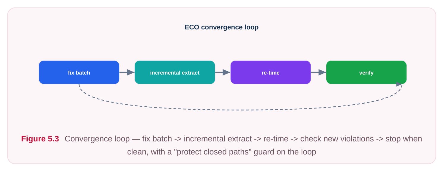
Convergence is declared only when a full, SI-aware re-extraction and timing run shows no new violations and the design-rule and noise checks are clean. Because each pass is small, several iterations are normal; the sign of trouble is a count that bounces up and down rather than trending to zero, which usually means two fixes are in conflict and the order or scope needs rethinking.
Interview Q&A
parasitics—Steiner-tree wirelength, assumed layers, no via resistance, and no coupling. The real router takes detours, may push the net onto thin resistive metal, adds vias, and creates physical neighbors that introduce coupling capacitance. The result is more delay and, with SI enabled, crosstalk-induced delta delay. A path with thin pre-route margin can therefore tip into violation once real RC and SI are applied. The fix is incremental, layer-aware editing followed by re-extraction.
transform here? It means swapping a cell for a drive-strength variant that occupies the same placement site and the same pin geometry, so the existing routing reconnects with essentially no disturbance. It is preferred because the cells are placed and routed; any change that moves a cell or alters its pin locations forces legalization and rerouting, which risks breaking neighboring nets and closed timing. Footprint-preserving sizing gets you a delay or slew change for the lowest possible physical cost.
delta-delay failure (timing) or a noise glitch (functional/electrical). Then choose the least disruptive remedy: strengthen the victim driver (often footprint-preserving), increase spacing, add a grounded shield, or move the victim to a quieter track or layer. Each remedy consumes routing resources, so you re-extract incrementally and re-check both the victim and its new neighbors, since spacing one net can crowd another. SI fixes are usually done as a dedicated SI-aware pass after setup and DRV cleanup.
depends on the smallest path delays and is extremely sensitive to short-net delay, which only becomes accurate after real extraction—so you want stable, final RC before committing hold buffers. It is fixed last because setup fixes (upsizing, buffering) change delays and can create or relieve hold
issues; doing hold first means redoing it. Fixing hold too aggressively over-buffers the design, adding area, leakage, and dynamic power, and can erode setup on shared path segments. The goal is just enough delay to clear the violation with a small, controlled margin.
Key Takeaways
- Post-route is the most constrained stage: real extracted parasitics and real crosstalk are present, and every edit must be small, locally re-routed, and re-extracted.
- This pass exists because pre-route estimates miss detours, layer assignment, via resistance, and coupling—gaps that surface as fresh setup, hold, transition, capacitance, and SI violations.
- Work incrementally: measure, make a minimal edit, re-extract the touched nets, re-time, and check for newly created violations.
- Allowed transforms are footprint-preserving sizing, spare/in-place edits, targeted buffering on routed nets, and layer/via/shield fixes. Logic restructuring, large re-placement, clock-tree changes, and global reroutes are forbidden here.
- Tie every fix to the constraint it satisfies, start from conservative defaults and go aggressive only on stubborn paths, fix setup and DRVs before SI before hold, and protect already-closed timing throughout.
Comments
Leave a Reply