 ChipBuddy
← Home
ChipBuddy
← Home
Signal-Integrity Fixes
Up to this point in the flow, we have treated each net as an island. A driver pushes a transition onto a wire, the wire has some lumped resistance and capacitance, and the receiver eventually sees an edge arrive. That model is comfortable, and it is exactly what static timing analysis assumed before detailed routing existed. The problem is that real metal lines do not live in isolation. They run side by side, often for hundreds of microns, separated by only a fraction of the minimum spacing. Once you have actual geometry, those neighbors start to talk to each other, and the polite single-net model quietly breaks. This chapter is about what that conversation does to your timing and your robustness, and how to make the offending nets quiet down. Signal integrity (SI) is not an optional luxury sign-off; on modern nodes it routinely flips a comfortably-passing path into a violation, and a misdiagnosed SI failure can survive all the way to silicon as an intermittent functional bug.
Why SI Only Shows Up After Routing
You cannot analyze coupling you have not yet created. Before detailed routing, the parasitic estimate for a net is a rough function of its fanout and estimated length, and there is no notion of which other net happens to run beside it. The coupling capacitance between two specific wires depends on how long they run parallel, how far apart they are, and on which metal layers — information that simply does not exist until the router has committed. That is why SI is a post-route concern. After detailed routing and parasitic extraction, your timing model splits the capacitance of every net into two buckets: the grounded capacitance to substrate
and far-away structures, and the coupling capacitance to specific neighboring nets. It is that second bucket that creates the trouble. Crosstalk: aggressor couples onto victim aggressor victim coupling capacitance pushes/pulls the victim edge
Figure 7.1 Two parallel wires (aggressor on top, victim below) with coupling capacitors drawn between them;
ground caps drawn from each wire down to substrate When an aggressor net switches, charge flows through the coupling capacitor into the victim net. If the victim is also switching, that injected charge can speed it up or slow it down — crosstalk delta-delay. If the victim is supposed to be holding a steady value, the injected charge produces a transient bump — an SI glitch (also called crosstalk noise). And because the coupling current distorts the shape of the victim's edge, you also get SI-induced slew degradation: the victim's transition becomes slower or kinked, which then propagates as extra delay downstream.
The Coupling Mechanism in Detail
The physics is straightforward capacitive coupling. The coupling capacitor passes a current proportional to the rate of change of the voltage difference across it. Two facts fall directly out of that. First, the effect depends on what the two nets do at the same time. If the aggressor is quiet while the victim switches, the voltage across the coupling cap changes only because of the victim, and the neighbor behaves like ordinary grounded capacitance. The aggressor only injects energy when it switches during the victim's transition. STA captures this with timing windows: each net has an arrival-time window during which it can switch. If the aggressor's switching window does not overlap the victim's, that aggressor is not a credible threat and a good analysis will not pile on its worst-case effect. Second, the direction of the aggressor matters:
- Aggressor switching the same direction as the victim helps the victim along — the coupling current adds to the victim's own drive, so the edge arrives early (negative delta-delay).
- Aggressor switching the opposite direction fights the victim — the edge arrives late (positive delta-delay). A subtle and important effect is the Miller behavior: when both ends of the coupling cap move in opposite directions, the effective capacitance the victim driver must charge roughly doubles, which is why opposite-direction aggression is so punishing.
WHY A FAST AGGRESSOR NEAR A SLOW VICTIM IS THE WORST CASE
The amount of charge dumped into the victim scales with how fast the aggressor edge is — a sharp aggressor slew injects a large, concentrated current spike. Meanwhile, how badly that charge disturbs the victim depends on how weakly the victim resists it. A slow, weakly-driven victim (small driver, long resistive wire, high capacitance) has a high impedance to ground at the point of injection, so the same injected charge produces a larger voltage excursion and a larger delay shift. Combine the two and the canonical worst case is a strong, fast aggressor coupling onto a weak, slow victim. Recognizing this pairing immediately tells you which lever to reach for. Crosstalk: aggressor couples onto victim aggressor victim coupling capacitance pushes/pulls the victim edge
Figure 7.2 Timing-window overlap chart — victim window bar, aggressor window bar, with overlap region shaded
as "credible coupling"
Table 1 — SI Violation Types
| Violation type | What it does | Root cause | First-line fix |
|---|---|---|---|
| Crosstalk delta- | Opposite-direction aggressor | High coupling cap + | Spacing/shielding, upsize |
| delay (setup) | pushes victim edge late, eating setup slack | overlapping windows + weak victim | victim driver, reduce overlap |
| Crosstalk delta- | Same-direction aggressor pulls | High coupling cap + | Spacing, downsize/align |
| delay (hold) | victim edge early, eating hold | overlapping windows slack | aggressor, add hold delay carefully |
| SI glitch (noise) | Transient bump on a quiet victim crosses the noise threshold | Strong aggressor, weak/ floating victim, high coupling ratio | Stronger victim keeper/ driver, isolate, buffer, keep-away |
| SI slew | Victim edge distorted/slowed, | Coupling reshaping the | Same driver/wiring levers |
| degradation | adding downstream delay | transition | as delta-delay |
Fixing Crosstalk Delta-Delay
Delta-delay is a timing problem caused by SI, so you can attack it either by reducing the coupling or by strengthening the victim. The common levers, roughly in order of cost:
- Increase spacing. Coupling capacitance falls steeply as the gap between victim and aggressor grows. Telling the router to add non-default spacing to a critical net is often the cheapest, lowest- risk fix.
- Shield the victim. Route a grounded or power line on each side of the victim. The shield intercepts the field lines that would otherwise couple, converting harmful coupling cap into harmless grounded cap. Expensive in routing resources — reserve it for the few truly critical nets (clocks, sensitive async signals).
- Upsize the victim driver. A stronger driver lowers the victim's impedance, so injected charge produces a smaller excursion and the edge is more resistant to being pushed. This is the go-to fix when rerouting is hard.
- Downsize or slow the aggressor. A weaker or slower aggressor injects less charge. Only do this where the aggressor has slack to spare — slowing it down spends its timing margin.
- Align or separate timing windows. If you can shift the aggressor's switching window out of the victim's window (different clock phase, added delay on the aggressor), the coupling stops being credible. Conversely, deliberately aligning a same-direction pair can help.
- Layer promotion. Moving the victim to a higher, wider metal layer with lower resistance and thicker dielectric reduces both the victim's own RC and its susceptibility.
- Net ordering / track assignment. Asking the router to reorder tracks so the critical net does not sit between two aggressive neighbors is a cheap structural fix when done early.
Table 2 — Aggressor / Victim Factors
| Factor | Makes coupling worse | Makes coupling better |
|---|---|---|
| Coupling capacitance | Long parallel run, tight spacing | Spacing, shielding, layer change |
| Aggressor strength | Strong driver, fast slew | Downsize/slow aggressor (if it has slack) |
| Victim strength | Weak driver, long resistive net | Upsize driver, buffer, shorten/promote net |
| Timing-window overlap | Windows fully overlap | Shift windows apart |
| Switching direction | Opposite (delay), same (early) | Manage by re-phasing or alignment |
| Victim state for glitch | Quiet/floating, high impedance | Active keeper, strong hold |
Fixing SI Glitch
A glitch is a different animal because the victim is not switching — it is supposed to hold a level, and the coupled charge produces a spike. If that spike crosses the receiver's switching threshold, it can be
latched as a wrong value or propagate as a false transition. There is no timing slack to trade here; the fix is about robustness.
- Stronger driver / keeper. A victim held strongly to its rail will sink the injected charge with only a small bump. Upsizing the driver, or adding a keeper on a dynamic/floating node, raises the glitch immunity directly.
- Isolation and keep-away. Move the quiet sensitive net away from strong switching neighbors, or forbid routing it adjacent to known-aggressive buses.
- Buffer insertion. Breaking a long susceptible net into segments with a buffer reduces the length over which any single aggressor couples, and the buffer restores a clean level mid-net.
- Shielding. As with delta-delay, ground shields are the strongest fix for the few nets that truly cannot tolerate noise. The trap with glitch fixes is to confuse them with delay fixes. A glitch on a static net never appears in a setup/hold report; you find it only in a dedicated noise/glitch analysis. Always run both.
Fixing SI Slew
Slew degradation is really delta-delay's quieter cousin: the same coupling that shifts an edge in time also distorts its shape. A victim edge that arrives kinked or stretched is read by downstream cells as a slow input, and slow inputs mean extra delay and even more SI susceptibility — a vicious cycle. The fixes are identical to the delta-delay levers: strengthen the victim driver, reduce coupling by spacing or shielding, and keep aggressors off the net's flanks. The reason to call it out separately is that it shows where SI fixes interact with ordinary timing closure: cleaning up a victim's slew can recover delay on the victim and on every cell it feeds, so an SI slew fix sometimes pays for itself across multiple paths.
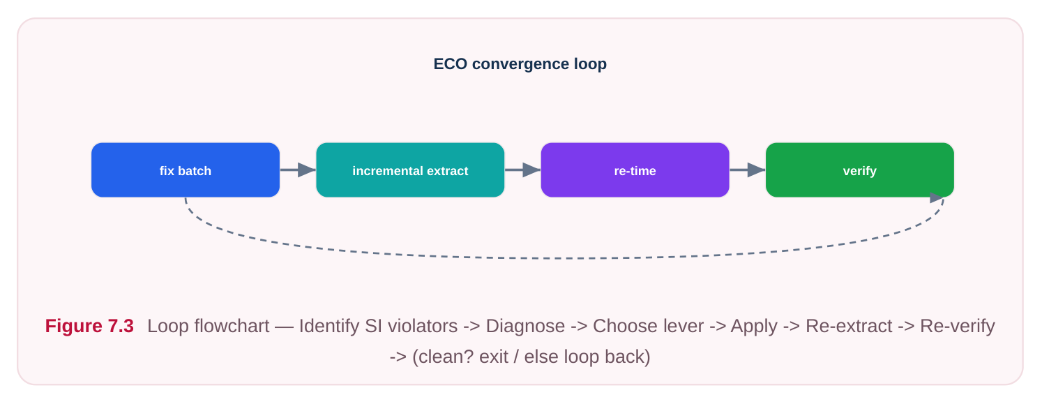
The SI Analysis and Fix Loop
SI repair is iterative because every fix changes the geometry, and changed geometry means the parasitics must be re-extracted before you can trust the result. The disciplined loop:
- 1. Identify SI violators. Run SI-aware timing and noise analysis; collect paths failing due to delta-
delay and nets failing glitch checks. Sort by the size of the SI contribution, not just total slack.
- 2. Diagnose each net. Look at the dominant aggressors, coupling ratio, window overlap, and victim
drive strength. The aggressor/victim factor table tells you which lever fits.
- 3. Choose and apply a lever. Prefer cheap, local fixes (spacing, driver sizing) before structural ones
(shielding, rerouting).
- 4. Re-extract parasitics. This is non-negotiable — SI numbers from stale parasitics are fiction.
- 5. Re-verify. Re-run SI timing and noise. Confirm the target net is clean and that you did not push a
neighbor into violation (a classic side effect of upsizing a driver, which makes that net a stronger aggressor to someone else).
- 6. Repeat until clean.
Generic Command Sketches
Reporting and inspecting SI. The reporting query below uses a standard SDC-style flag to fold SI into the timing analysis; the dedicated SI/noise reports themselves are tool-specific in spelling, so treat the command names as illustrative.
# Enable SI-aware timing during analysis
set_si_delay_analysis_mode -enabled true   ;# illustrative — generic, not tool-
specific
# Report the paths whose failures are driven by crosstalk
report_timing -path_type full -nworst 20   ;# standard (SDC-style switches)
# Dump the SI delta-delay contribution and dominant aggressors on a net
report_crosstalk -net VICTIM_NET -aggressors  ;# illustrative — generic, not tool-
specific
# Report noise/glitch margin against the receiver threshold
report_noise -net VICTIM_NET                ;# illustrative — generic, not tool-
specific
Applying a delta-delay or slew fix. Spacing and driver sizing are the workhorses:
# Ask the router to add extra spacing around a critical victim
set_routing_rule -net VICTIM_NET -spacing 2x   ;# illustrative — generic, not tool-
specific
# Upsize the victim driver to lower its impedance
size_cell U_victim_drv DRV_X4                   ;# illustrative — generic, not tool-
specific
# Promote the net to a higher, wider, lower-R layer
set_net_layer_constraint -net VICTIM_NET \
-min_layer M5 -max_layer M7                 ;# illustrative — generic, not tool-
specific
Shielding a sensitive net and re-extracting:
# Insert grounded shields on both sides of the victim
create_shield -net VICTIM_NET -shield_net VSS \
-sides both                                 ;# illustrative — generic, not tool-
specific
# Re-extract parasitics so SI numbers reflect the new geometry
extract_parasitics -coupled                     ;# illustrative — generic, not tool-
specific
# Re-verify SI timing and noise after the fix
report_timing -nworst 20                         ;# standard (SDC-style switches)
report_noise                                     ;# illustrative — generic, not tool-
specific
Table 3 — Lever Selection Cheat Sheet
| Symptom | Cheapest effective lever | When to escalate |
|---|---|---|
| Small setup delta-delay on one net | Increase spacing | Upsize victim if rerouting |
blocked
| Large delta-delay, weak victim | Upsize victim driver | Promote layer + spacing |
|---|---|---|
| Hold delta-delay (early edge) | Reduce coupling / align | Shield if a clock/async net |
windows
| Glitch on quiet net | Strengthen driver / keeper | Shield + keep-away |
|---|---|---|
| Slew degradation cascading | Upsize victim driver | Buffer insertion + spacing |
downstream
Many victims on one bus Net ordering / track assignment Bus-wide shielding a victim driver turns that net into a stronger aggressor for its own neighbors. Adding spacing or shields consumes routing tracks that may force other nets closer together. This is why the loop insists on reextraction and re-verification of the whole neighborhood, not just the net you touched. SI closure is a balancing act, not a checklist.
Interview Q&A
defined between specific adjacent wires, and which wires run beside each other — and for how long, at what spacing, on which layers — does not exist until the router commits the geometry. Pre-route parasitics are length/fanout estimates with no neighbor information, so there is nothing to couple to. SI is inherently a post-route, post-extraction analysis.
check does it threaten? Same-direction switching injects current that aids the victim's transition, making the edge arrive earlier (negative delta-delay). An early edge is good for setup but dangerous for hold, since it can violate the minimum required delay. Opposite-direction switching does the reverse: it delays the edge and threatens setup. Always state the direction and the check together.
aggressor's edge rate, so a fast aggressor dumps a large, concentrated current spike. The resulting voltage disturbance scales with the victim's impedance, so a slow, weakly-driven, resistive victim turns that injected charge into a large excursion. Strong-fast aggressor plus weak-slow victim maximizes both terms. The natural fix is to strengthen the victim and/or slow or space away the aggressor.
fails. Why, and what does it tell you about the SI flow? The upsized driver makes its net switch faster and harder, so it is now a stronger aggressor to the nets beside it. This is the defining property of SI: fixes are coupled. It is why the analysis loop mandates re-extracting parasitics and re-verifying the surrounding neighborhood after every change, rather than declaring victory on the single net you targeted.
Key Takeaways
- SI is a post-route phenomenon: extraction splits net capacitance into grounded and coupling components, and the coupling component drives crosstalk delta-delay, glitch, and slew degradation.
- Coupling current depends on the rate of change of the voltage difference across the coupling cap, so it matters only when aggressor and victim switch in overlapping timing windows; direction sets whether the victim speeds up (hold risk) or slows down (setup risk).
- The canonical worst case is a strong, fast aggressor coupling onto a weak, slow victim — diagnose the pairing first, then pick the lever.
- Delta-delay and slew fixes share levers: spacing, shielding, victim upsizing, aggressor downsizing, window separation, layer promotion, and net ordering. Glitch fixes emphasize robustness — stronger driver/keeper, isolation, buffering, keep-away.
- The flow is a loop: identify violators, diagnose, apply a lever, re-extract, re-verify the neighborhood — never just the net you touched. SI fixes are coupled, so each change can create the next violation.
Comments
Leave a Reply