 ChipBuddy
← Home
ChipBuddy
← Home
Pre-CTS (Ideal-Clock) Optimization
Chapter 3 — Pre-CTS (Ideal-Clock) Optimization
Pre-CTS optimization is the stage every physical-design engineer learns to love, because it is the freest the optimizer will ever be. The clock tree does not yet exist. The clock is ideal — it arrives at every register at exactly the same instant with zero skew, zero insertion delay, and (depending on how you have configured it) either zero or a single estimated transition. With that simplifying assumption in place, the optimizer is free to attack the datapath with a wide repertoire of transforms and a clear conscience: it does not have to worry about clock buffers, real skew, or the hold consequences of a tree that has not been built. This chapter explains what the optimizer does in this window, why it does it in this order, which violations it cares about now versus later, and how you read the results to decide when the design is "good enough for CTS."
Why pre-CTS is the freest stage
After global placement, every cell has a legal-ish location and the netlist topology is fixed in the sense that the logic function is frozen — but almost everything physical about a gate is still negotiable. The optimizer can change a cell's drive strength, swap it for a functionally equivalent gate with a different threshold voltage, insert or delete buffers, restructure a chain of logic into a flatter or deeper form, swap commutative input pins to give a critical signal the faster path, and even duplicate a high-fanout driver so two halves of its load are served separately. None of these moves disturb the clock, because the clock is still an abstraction.
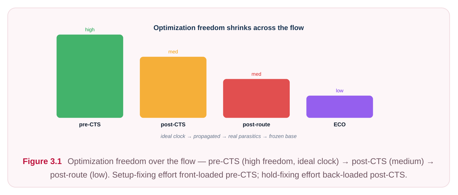
This is the moment to be aggressive. Once the clock tree is physically built (post-CTS), real skew and real insertion delay lock in, and large restructuring becomes risky: moving or resizing logic can ripple into hold paths the tree now defines, and big topology changes can invalidate the carefully balanced tree. So the discipline is simple — close as much setup as you possibly can while the clock is ideal, and leave only the residual, location-sensitive cleanup for later.
First-pass violation correction on an ideal clock
When you launch the first pre-CTS optimization, the engine builds a timing graph using ideal clock arrival, the current parasitic estimate (from a virtual or early extraction model), and the standard-cell library timing. It then computes slack on every endpoint and the design-rule violations (DRVs) on every net. Two things dominate this pass: worst negative slack (WNS) on setup paths and DRVs — specifically max-transition and max-capacitance. The optimizer typically prioritizes the most negative setup paths first, walking the critical path and applying whichever transform yields the largest slack improvement for the smallest cost. It works on the worst paths, then the next-worst, and in parallel cleans up transition and capacitance violations because those distort the very delay numbers it is trying to optimize — a net with a 2 ns transition has unreliable delay, so fixing the DRV is a prerequisite for trusting the timing.
# illustrative — generic, not tool-specific
# First pre-CTS optimization pass on an ideal clock
set_optimization_effort -setup high
set_optimization_effort -drv  high
optimize_design -pre_cts -fix_setup -fix_drv
report_timing -setup -max_paths 20 -path_type full_clock
A key mental model: pre-CTS slack is optimistic relative to what you will see after CTS, precisely because skew is zero. A path that is barely passing now may fail once real skew arrives. Experienced engineers therefore close setup to a small positive margin pre-CTS rather than to exactly zero, leaving headroom for the skew and insertion-delay reality that CTS introduces.
It is also worth understanding the order in which the engine attacks problems within a single pass. Most optimizers operate on a priority queue of violations sorted by criticality, so the worst negative path is processed first and the rest follow in descending severity. After each transform the local timing is re-evaluated incrementally — the engine does not recompute the whole graph for every gate it touches, which is what makes large pre-CTS runs tractable. A subtle consequence is that fixing the single worst path can change which path is now worst, so the optimizer loops: pick the worst, improve it, re-rank, repeat, until either the queue is empty or no transform can make further progress without violating a constraint. This is why a design with one deep outlier path and a design with thousands of marginally failing paths behave so differently — the former converges quickly, the latter may need constraint or floorplan attention rather than more optimization effort.
The main pre-CTS transforms
The optimizer's power comes from a toolbox of behavior-preserving transforms. Understanding each one — what it fixes and what it costs — is exactly the kind of thing interviewers probe, because it reveals whether you understand why the tool does what it does. Gate sizing (upsizing/downsizing). The most common transform. Upsizing a gate increases its drive strength, reducing the delay it contributes when it drives a heavy load — at the cost of more area, more input-pin capacitance (which can slow the previous stage), and more leakage and dynamic power. Downsizing recovers area and power on non-critical paths. Buffering and de-buffering. Inserting a buffer (or inverter pair) on a long, high-fanout, or highcapacitance net splits the load, repairs transition/cap DRVs, and can isolate a critical sink from a slow driver. De-buffering removes redundant buffers that placement made unnecessary, recovering area and power. Buffering is the workhorse for DRV repair. Logic restructuring and remapping. The optimizer can re-balance a logic cone — for example, flattening a deep chain of two-input gates into a shallower tree, or remapping a function onto different library cells (a complex AOI/OAI cell instead of discrete gates). This reduces the number of logic levels on a critical path, which is often the only way to fix a path that sizing alone cannot rescue. Pin swapping. On commutative inputs (e.g., the inputs of an AND or a symmetric mux), the optimizer routes the latest-arriving / most-critical signal to the input with the fastest pin-to-output arc. Zero area cost, zero power cost — a "free" win, so the optimizer reaches for it early. Cloning high-fanout drivers. When one gate drives many sinks, the optimizer can duplicate the driver so each copy serves a subset of the load. This lowers per-driver load and lets each clone be
placed nearer its sinks, cutting both delay and transition. Cost: extra area and the upstream load of the duplicated input. Vt-aware (threshold-voltage) swapping. In a multi-Vt library, a low-Vt cell switches faster but leaks far more; a high-Vt cell is slower but very low leakage. Pre-CTS, the optimizer can swap critical-path cells to lower Vt to gain speed, and swap non-critical cells to higher Vt to claw back leakage — the foundation of leakage-power optimization without hurting timing.
| Transform | Primarily fixes | Main cost |
|---|---|---|
| Gate upsizing | Setup (drive/delay), transition | Area, leakage, dynamic power, upstream |
load
Buffering Max-transition, max-cap, long Area, power, extra delay stage
| De-buffering | (recovers) area/power | Slight risk to DRV if over-aggressive |
|---|---|---|
| Logic restructuring/ | Setup via fewer logic levels | Runtime, possible new DRVs |
remapping
| Pin swapping | Setup on commutative inputs | None (essentially free) |
|---|---|---|
| Driver cloning | Setup + transition on high | Area, upstream load |
fanout
| Vt swap to low-Vt | Setup (speed) | Leakage power |
|---|---|---|
| Vt swap to high-Vt | (recovers) leakage | Setup margin if mis-applied |
Why hold is mostly deferred — but DRVs are not
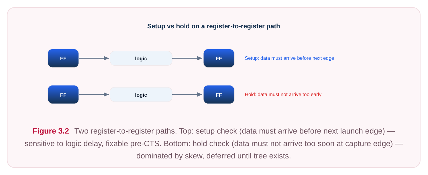
This is one of the most important pre-CTS concepts, and a classic interview question. On an ideal clock, hold timing is essentially meaningless to fix aggressively, and here is the intuition. A hold check asks whether the data at a register's input is held stable long enough after the active clock edge — it compares the data arrival to the capture clock edge at the same register's clock pin. Hold violations are overwhelmingly created by clock skew: when the capture register's clock arrives later than the launch register's clock, the data can race through and corrupt the capture. With an ideal clock, skew is zero everywhere, so the skew-driven hold problems simply do not exist yet. Fixing hold now — by padding paths with delay buffers — would be wasted effort, because CTS will rebuild the skew picture entirely and you would have to redo it. Worse, hold buffers added pre-CTS can clutter the design and make CTS harder. So hold is deferred to post-CTS (and post-route), where real skew is known. Pre-CTS you watch hold, you may note egregious structural hold issues, but you do not chase them. DRVs, however, cannot be deferred. Max-transition and max-capacitance violations are not about the clock at all — they are about a driver being too weak for its load, regardless of skew. A slow transition degrades cell delay accuracy, increases short-circuit power, and can cause functional and reliability problems. Because every delay calculation the optimizer makes depends on clean transitions, you must control transition and cap now so that the setup numbers you are optimizing against are trustworthy. The rule of thumb: fix setup and DRVs pre-CTS; defer hold to post-CTS.
Additional levers and effort settings
Beyond the transforms themselves, you control how hard the optimizer works and what it is allowed to trade. Effort settings (often low/medium/high) trade runtime for quality of results; higher effort lets the engine try more candidate transforms per net and iterate more. You can scope optimization to setup only, DRV only, or both. You can also bias the objective toward area or power so the engine does not over-size the whole design chasing a few critical paths. A frequent mistake juniors make is running everything at maximum effort with no area or power awareness, producing a design that meets timing but is bloated and leaky. The professional approach is layered: get setup and DRVs healthy first, then run area/power recovery on the non-critical logic that has slack to spare. There are several secondary levers worth knowing because interviewers like to see whether you reach beyond sizing. Placement-aware optimization lets the engine move cells as it sizes them, which matters because a freshly upsized gate is physically larger and may overlap neighbours or worsen local congestion; coupling sizing with incremental legalization keeps the result physically realizable. High-fanout net synthesis (HFNS) addresses nets — such as resets, enables, or scan-enables — whose fanout is so large that no single driver can meet transition; the engine builds a small buffer tree for them pre-CTS, distinct from the clock tree. Useful-skew intent, while it cannot be fully realized until the tree exists, can be hinted at pre-CTS by leaving margin on paths the engine expects CTS to help. Finally, don't-touch and size-only attributes let you protect hand-instantiated cells, clock-gating logic, or IP boundaries from being restructured — a common requirement when parts of the netlist must remain bit-accurate to the source RTL or to a third-party block.
Knowing which lever to reach for is largely about diagnosing why a path fails. If the path has few logic levels but heavy load, sizing and buffering win. If it has many logic levels, restructuring is the answer. If it fails only on one corner, the fix may be a Vt swap or a constraint review rather than a structural change. Treating every violation with the same hammer — upsizing — is the hallmark of an inexperienced flow.
# illustrative — generic, not tool-specific
# Layered pre-CTS strategy: timing first, then recover area/power on slack
set_optimization_effort -global medium
optimize_design -pre_cts -fix_setup -fix_drv
# Recover area and leakage where slack permits (downsizing, high-Vt swaps)
set_power_optimization -leakage true -dynamic true
optimize_design -pre_cts -recover_area -recover_power
report_qor
You also control the constraints that frame all of this. The SDC drives everything — clock period, input/ output delays, and the ideal-clock assumption itself. Two genuine SDC commands worth knowing in this context: declaring a clock as ideal (no propagation), and setting design-rule limits the optimizer must honor.
# standard (SDC)
create_clock -name clk -period 2.0 [get_ports clk]
set_clock_uncertainty 0.10 [get_clocks clk]   ;# pre-CTS skew/jitter budget
set_max_transition 0.15 [current_design]
set_max_capacitance 0.20 [current_design]
# Keep the clock ideal pre-CTS: do NOT set_propagated_clock yet
The set_clock_uncertainty line is worth dwelling on. Because the clock is ideal and you know CTS will add skew you cannot model yet, you reserve a pessimism budget by subtracting an uncertainty from the period. This forces the optimizer to close setup with margin — a synthetic stand-in for the skew, jitter, and insertion-delay variation that the real tree will bring. Choosing this number well is part of the craft: too small and paths fail after CTS; too large and you over-optimize, burning area and power.
Re-running incrementally and reading the results
Pre-CTS optimization is iterative. You rarely close timing in a single command. After the first pass you read the reports, possibly adjust effort, constraints, or placement (congestion can block sizing), and rerun incrementally so the engine preserves prior work and only touches what still needs fixing. Incremental runs converge faster and avoid the churn of starting over. Reading the results, focus on a small set of numbers: WNS (the single worst path — is it positive with margin?), TNS (total negative slack — how much total violation remains across all endpoints, indicating breadth versus a single outlier?), the count of failing endpoints, the transition/cap DRV counts (these should trend to zero), and the area/leakage trend (are you paying too much for the timing you gained?).
# illustrative — generic, not tool-specific
# Read the pre-CTS scorecard before deciding to proceed
report_timing  -setup -max_paths 50 -slack_lesser_than 0.0
report_constraint -max_transition -max_capacitance -all_violators
report_qor       ;# WNS, TNS, failing endpoints, area, leakage
WHEN IS IT "GOOD ENOUGH FOR CTS"? There is no universal number, but a healthy pre-CTS handoff usually shows: setup WNS positive (or only slightly negative on a handful of paths that you expect CTS-driven useful skew to help), DRVs at or near zero, no large pockets of TNS suggesting a structural problem, and area/power within the floorplan budget. If WNS is deeply negative or hundreds of endpoints fail, do not push to CTS — the tree will only make a bad situation worse. The goal is to enter CTS with a datapath that is timing-clean under ideal-clock assumptions plus a reasonable uncertainty margin, so that CTS and post-CTS optimization deal only with the incremental problems the real clock introduces.
| Pre-CTS exit checklist | Target |
|---|---|
| Setup WNS | Positive, with margin for CTS skew (uncertainty budgeted) |
| Setup TNS | Small / no large structural pockets |
| Failing endpoints | Few and understood, not hundreds |
| Max-transition violators | Zero (or negligible, justified) |
| Max-capacitance violators | Zero |
| Hold violations | Noted but NOT chased (deferred to post-CTS) |
| Area utilization | Within floorplan budget |
| Leakage / dynamic power | Recovered on slack-rich logic |
| Congestion | Not blocking sizing/buffering |
| Clock | Still ideal (propagation not yet enabled) |
Interview Q&A
clock skew, and on an ideal clock skew is zero by definition. The hold check compares data arrival against the capture register's own clock edge; without real skew, the racing problem that causes hold failures does not yet exist. Any hold padding you add now would have to be reworked once CTS builds the real tree and changes the skew picture entirely — so it is wasted effort, and the buffers can even complicate CTS. Hold is therefore deferred to post-CTS, where skew is known.
do with the clock. A max-transition or max-cap violation means a driver is too weak for its load — that
is a datapath/physical issue independent of skew. Crucially, every delay number the optimizer computes assumes reasonable transitions; a degraded slew makes delay calculations unreliable. So you must clean transitions and caps before trusting any setup optimization, plus slow slews waste power and hurt reliability. DRVs are immediate; hold is deferrable.
Pre-CTS slack is optimistic because skew is zero. CTS will introduce real skew, insertion delay, and jitter, which generally erode setup margin on many paths. Closing to exactly zero means those paths will fail post-CTS. You want positive WNS with a margin, which is exactly why you budget a clock uncertainty pre-CTS — it forces the optimizer to leave headroom for the skew reality CTS brings.
returns once a path is dominated by logic depth rather than drive strength — bigger gates add input load that offsets their own speedup. The next levers are structural: logic restructuring/remapping to reduce the number of logic levels, pin swapping to put the late-arriving signal on the fastest input arc, driver cloning to relieve a high-fanout bottleneck, and low-Vt swaps on the critical cells. If those still fail, the problem is likely architectural (path is simply too long for the clock period) and may require constraint review, register retiming, or pipelining feedback to the front end.
Key Takeaways
- Pre-CTS is the freest optimization stage: the clock is ideal, so the engine can size, buffer, restructure, remap, pin-swap, clone, and Vt-swap aggressively to close setup before any tree exists.
- Fix setup and DRVs (max-transition, max-cap) now; defer hold to post-CTS, because hold is skew-driven and skew is zero on an ideal clock.
- DRVs must be clean because every delay calculation depends on trustworthy transitions — fixing slew is a prerequisite for trustworthy setup optimization.
- Each transform trades a benefit for a cost (area, power, upstream load); use layered effort — timing first, then area/power recovery on slack-rich logic.
- Pre-CTS slack is optimistic; budget a clock uncertainty so the optimizer closes setup with margin for the skew CTS will introduce.
- Re-run incrementally and read WNS, TNS, failing-endpoint count, and DRV counts. Hand off to CTS only when setup is positive-with-margin, DRVs are near zero, and area/power are within budget.
Comments
Leave a Reply