 ChipBuddy
← Home
ChipBuddy
← Home
Why Crosstalk Earns Its Own Deep Chapter
In tiny chips, wires are tall, thin, and packed close. So a wire's biggest capacitance (its ability to store charge) is often to its neighbour, not to ground. When the neighbour switches, it pushes charge across the gap. We call the switching wire the aggressor. We call the affected wire the victim. Think of two boats side by side. When one rocks, its wake rocks the other. This creates two kinds of failure. Sign-off must catch both. First, the victim's delay can change. This moves timing. Second, the victim can get a glitch (a brief unwanted voltage bump). This can corrupt a value. This chapter shows how a timing tool measures and settles these effects. Crosstalk: aggressor couples onto victim aggressor victim coupling capacitance pushes/pulls the victim edge
Figure 22.1 Two parallel routed wires (aggressor above, victim below) with coupling capacitors between them and
arrows showing charge injection
The Iterative Crosstalk-Aware Timing Loop
Crosstalk has a chicken-and-egg problem. How much an aggressor hurts a victim depends on when each one switches. But switching times are exactly what timing wants to find. Tools break this loop by looping. They repeat the steps until things settle.
- 1. Run a first timing pass with no coupling. This gives arrival windows for every net.
- 2. For each victim, find aggressors that switch at the same time. Compute a delta delay (the extra or
reduced delay from coupling).
- 3. Apply the delta delays. This shifts the arrival windows.
- 4. Recompute the windows. Some overlaps appear. Others go away. Repeat until windows and deltas
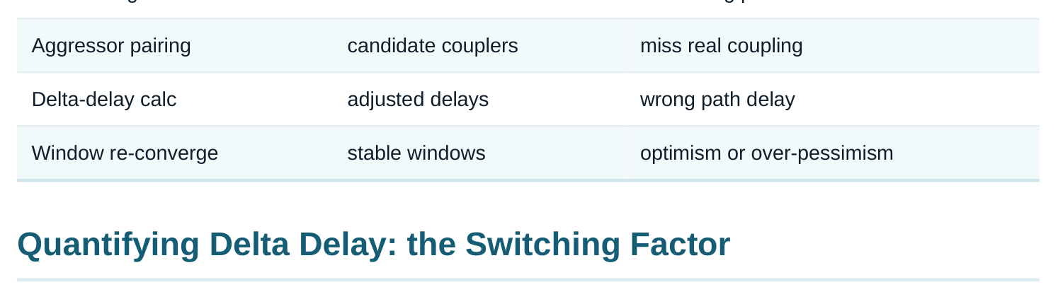
stop moving. This is convergence. Skipping convergence is risky. You may miss a real overlap. That is optimism. Or you may assume every aggressor aligns at the worst time. That is too much pessimism. Good sign-off checks that the loop converged. It also checks the loop did not stop early with violations still moving.
Crosstalk & Noise: A Deep Dive
| Loop stage | Produces | Risk if skipped |
|---|---|---|
| Base timing | nominal windows | no starting point |
The coupling capacitance does not always feel the same. What matters is the relative motion of the two wires while the victim switches. Tools often model this with a switching factor on the coupling cap Cc . The factor changes how big Cc seems.
- Aggressor stays quiet while the victim switches. The victim sees about
1×Cc. This is just extra grounded cap. The slowdown is small. - Aggressor switches the same way as the victim, at the same time. The coupling can drop toward
0×Cc. This speeds the victim up. The delta delay is negative. - Aggressor switches the opposite way, at the same time. The coupling can rise toward
2×Cc. This slows the victim a lot. The delta delay is positive. This is the setup-killer. So the same physicalCccan act from 0× up to 2×. It depends on direction and timing. The effect also grows with a strong, fast aggressor. A fast aggressor pushes more charge. It also grows when the victim driver is weak. A weak driver cannot fight back.
# illustrative — generic, not tool-specific
# enable coupled (SI) timing and report the delta-delay contributors
set_si_analysis -enable true
report_delta_delay -net victim_net -worst
Worked example — effective cap with a switching factor
Say a victim net has 8 fF to ground. It has 5 fF of coupling to one aggressor.
- Aggressor opposite-direction, aligned: effective cap ≈ 8 + 2×5 = 18 fF.
- Aggressor quiet: effective cap ≈ 8 + 1×5 = 13 fF.
- Aggressor same-direction, aligned: effective cap ≈ 8 + 0×5 = 8 fF. Suppose this driver adds about 0.08 ns per fF of extra load (an illustrative slope). The worst opposite- direction case adds (18−13)×0.08 = +0.4 ns of delta delay versus the quiet baseline. The same- direction case subtracts about 0.4 ns. STA applies the +0.4 ns to the setup (late) check. It applies the −0.4 ns to the hold (early) check. Each one is pessimistic for its own check. Aggressor behaviour Effective Cc factor Effect on victim Hurts which check Quiet 1× mild slow — Same direction, aligned →0× speed up hold Opposite direction, aligned →2× slow down setup
Timing Windows in Depth
A delta delay only counts if the aggressor can switch while the victim switches. So the tool finds a switching window for each net. The window runs from the earliest to the latest possible transition. The tool only couples nets whose windows overlap.
- No overlap means no impact. Say an aggressor can only switch when the victim is already settled. Then it is filtered out. This removes a lot of false pessimism.
- Overlap means worst alignment is assumed. This is conservative. Some tools instead model the probability.
- Windows move as deltas are applied. This is why the loop must re-converge.
Crosstalk: aggressor couples onto victim aggressor victim coupling capacitance pushes/pulls the victim edge
Figure 22.2 Timing-window overlap chart — victim window bar, aggressor window bar, the overlap region
highlighted as the only coupling-relevant zone Many aggressors make this harder. The worst case is not always all aggressors aligning at once. Their own windows may never overlap each other. So tools group by windows. They do not just add up every aggressor. Naive addition would be far too pessimistic.
| Window relationship | Coupling considered? | Note |
|---|---|---|
| Disjoint windows | no | filtered out |
| Partial overlap | yes, in overlap | re-converged |
| Full overlap | yes, worst align | most pessimistic |
Noise (Glitch) Analysis
Delta delay is about a switching victim. A quiet victim has a different problem. An aggressor can inject a bump. If the bump is big enough, it can read as a wrong value. It can also upset a latch.
- Noise margin: how big a bump a gate can take before its output changes. It has a DC part and an AC (short-lived) part. A quick spike is less risky than a long one.
- Propagation: a bump at a gate input becomes a smaller or larger bump at the output. Noise analysis follows these bumps. It checks if a bump reaches a flop or latch.
- Noise on clock vs data: a bump on a clock or an async set/reset is far worse than on plain data. It can cause a false capture or reset.
- Latched vs combinational victims: a bump at an open latch is the worst case. So is a bump near a flop's sampling moment.
# illustrative — generic, not tool-specificreport_noise -nets [get_clock_nets] -threshold marginreport_noise -type glitch -worst 20
Functional noise vs timing noise
Crosstalk gives two outcomes. They are fixed in different ways. A delta-delay problem is a timing failure. The path got slower or faster. Now it fails setup or hold. A glitch problem is a functional/noise failure. A value got corrupted. This has nothing to do with the clock period. A net can have one problem, both, or neither.
| Outcome | Symptom | Primary fix |
|---|---|---|
| Delta delay (setup) | path slower, setup fails | shield/space, upsize victim, slow/align aggressor |
| Delta delay (hold) | path faster, hold fails | same levers, plus hold buffers |
| Glitch (functional) | corrupted value/clock | isolate, stronger victim driver, keep-away |
Mitigations and Their STA-Visible Effect
The physical fixes do one of three things. They cut Cc . They cut the aggressor's injection. Or they make the victim stronger. Each fix shows up in the next SI timing pass as a smaller delta or bump.
- Spacing / non-default rules: wider spacing cuts the coupling cap directly.
- Shielding: a grounded wire between the two nets soaks up the coupling.
- Layer assignment / net ordering: move the victim away from a strong aggressor.
- Upsizing the victim driver: a stronger driver holds the net. The relative bump shrinks.
- Slowing or downsizing the aggressor / slew control: less injected charge. Here is the interview-level point. You pick a fix by which factor dominates that net. The factor is coupling cap, aggressor strength, or victim weakness. The SI-aware re-run is what proves the fix worked.
Interview Q&A
depend on delays. The tool alternates between computing windows and deltas. It repeats until they converge. Otherwise you may miss real overlaps. Or you may assume impossible worst-case alignments.
the aggressor's motion during the victim transition. Same-direction aligned switching can cancel toward 0×. The victim speeds up. A quiet aggressor is about 1×. Opposite-direction aligned switching can double toward 2×. The victim slows. Setup analysis takes the slowing case. Hold takes the speeding case.
switches. Then it cannot couple into that transition. So the tool filters it out. Window filtering removes a lot of false pessimism. Without it, every neighbour would be assumed worst-aligned.
problem on a switching victim. The path becomes faster or slower. A glitch is a functional/noise problem on a quiet victim. An injected bump can read as a wrong value or upset a latch. It does not depend on the clock period.
is the most dangerous. It can cause a false edge. That means an unwanted capture or reset. It corrupts state no matter the data-path timing. So clock and async nets get the tightest noise margins and first priority for shielding.
capacitance. Upsizing the victim driver targets victim weakness. Slowing or downsizing the aggressor targets injected charge. The right one depends on which factor dominates that net. The next SI-aware run confirms it.
Key Takeaways
- Crosstalk gives two separate failures: delta delay (timing) on switching victims and glitch/noise (functional) on quiet victims.
- Coupling is measured with a switching factor (≈0×–2× Cc). Direction and alignment set it. Opposite-aligned is the setup-killer. Same-aligned hurts hold.
- The analysis is iterative. Windows and deltas re-converge. Non-overlapping windows are filtered out to avoid false pessimism.
- Noise margins (DC+AC) and propagation decide glitch failures. Clock and async victims are the most dangerous.
- Mitigations (shield, space, upsize victim, tame aggressor) each target a different dominant factor. Re-running SI-aware timing proves they worked.
Comments
Leave a Reply