 ChipBuddy
← Home
ChipBuddy
← Home
When the Power Supply Itself Becomes a Timing Variable
Static timing analysis (STA, checking if signals arrive on time) usually assumes a clean supply. It assumes each cell gets its full, nominal voltage. Real silicon is messier. Current flows through the power network. That network has resistance and inductance. Current through it causes a voltage drop. So a switching cell may briefly run below its full voltage. Lower voltage means slower cells. Delay grows as voltage falls. So supply droop (a dip in supply voltage) directly slows the cell. That makes the power network a timing problem, not just a reliability one. This chapter links power-integrity effects to timing.

IR-drop (voltage lost to current flowing through resistance) comes in two kinds.
- Static (average) IR-drop is the steady loss. It comes from average current flowing through the resistive grid. The math is simple:
V_drop = I·R. It sets a baseline below the ideal rail. - Dynamic (transient) IR-drop is a brief, deeper dip. It happens when many cells switch at once. They demand a current spike. The grid and its capacitors cannot supply it instantly. Fast current changes hurt extra, because of the inductive term
L·di/dt. Clock edges are the classic cause. Huge numbers of flops and clock buffers switch together there. Think of static IR like a steady tax. Think of dynamic IR like a sudden crowd at a water tap. Type Cause Character Worst trigger Static IR average I·R steady offset high sustained activity Dynamic IR transient I·R + L·di/dt brief deep sag simultaneous switching (clock edge) One cell matters most for timing. It is the cell whose local rail dips while it switches on a critical path.
How Droop Enters the Timing Number
There are two ways to handle this. They differ in rigor.
- 1. Margin (derate) approach. Assume a worst-case droop everywhere. Characterize timing at that
lower voltage. Or just add a flat timing derate. This is simple. But it is pessimistic. It punishes cells that never actually droop.
- 2. Voltage-aware (IR-aware) timing. A power-integrity tool finds the real local voltage at each cell.
Timing then recomputes each cell's delay at its own voltage. This is far more accurate. It spends margin only where the grid is truly weak. The cost is an extra analysis and an annotation step.
# illustrative — generic, not tool-specific
# margin approach: derate timing to cover supply droop
set_timing_derate -late 1.06 -cell_delay   # ~6% slow-down budget for droop
# voltage-aware approach: annotate per-instance voltage from PI analysis
read_instance_voltage ir_drop.annotation
update_timing -voltage_aware true
Worked example — droop turning into delay
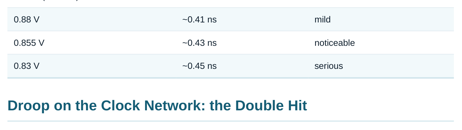
Suppose a critical cell runs at 0.90 V. Its stage delay is 0.40 ns. The local rail dips to 0.855 V during switching. That is a 5% sag. Assume delay grows about 1.5% for each 1% of voltage lost (illustrative). So a 5% droop adds about 7.5% delay. That gives 0.40 ns × 1.075 ≈ 0.43 ns. That is +0.03 ns on this stage alone. Now picture a path with several drooping stages. The extra delay adds up. It becomes real setup loss. A flat nominal-voltage analysis would miss it.
Supply Noise (IR-Drop) & EM Effects on Timing
| Local voltage | Stage delay | Setup impact |
|---|---|---|
| 0.90 V (nominal) | 0.40 ns | baseline |
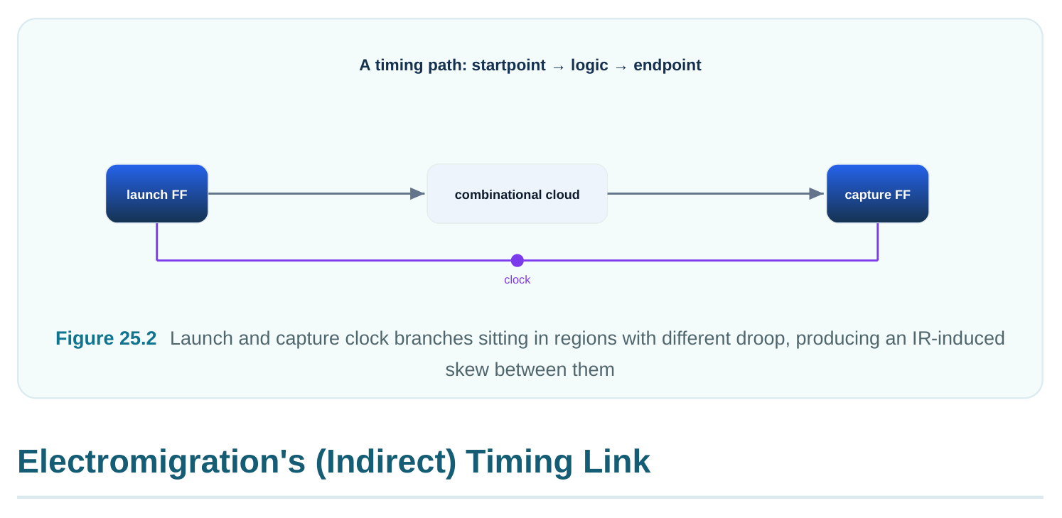
Droop on the clock tree is the most dangerous kind. It changes when clock edges arrive. That changes skew and jitter (timing spread between clock paths). The launch and capture branches may droop by different amounts. They sit in differently loaded parts of the grid. The result is extra skew. That skew can hurt setup or hold. There is a second hit. A dynamic dip right at the clock edge acts like added clock jitter. So poweraware sign-off treats clock IR with great care. That is also why decoupling capacitors are packed near clock drivers.
Electromigration (EM, metal slowly eroding under high current) is mainly a reliability limit. Sustained high current density wears away metal. Over the product's life, a wire can open or short. Its link to timing is indirect but real.
- EM rules cap the current a wire or via may carry. So high-activity nets need wider wires and more vias. Clock, power, and high-toggle nets are examples. Wider clock wires change R and C. That changes delay and slew. So EM-driven sizing feeds back into timing.
- A wire ages over its life. Its resistance slowly rises. That slowly shifts delay. Aging-aware sign-off adds margin. The chip must still meet timing at end-of-life, not just at day one. Effect Domain Timing link EM wire/via sizing reliability alters R/C → delay, slew Lifetime resistance rise aging delay drift, end-of-life margin Self-heating reliability/thermal higher local T → slower
Putting It Together: Power-Aware Sign-off
Good sign-off does not treat timing, power, and reliability as separate islands. It joins them.
- 1. Run power-integrity analysis. Get static and dynamic IR maps.
- 2. Feed per-cell and per-clock-branch voltages into voltage-aware timing.
- 3. Add aging and EM margins for end-of-life.
- 4. Check setup and hold still pass at the real local voltages. Watch clock paths most.
The interview message is simple. Nominal-voltage STA is only a start. Real silicon runs on a drooping, aging grid. Credible sign-off accounts for that. It does not hide behind one flat margin.
Interview Q&A
Lower voltage means more delay. Static IR sets a baseline offset. Dynamic IR adds a brief deep dip. That dip is worst at clock edges, from simultaneous switching. It slows critical cells and can fail setup.
worst-case droop everywhere and derates timing. It is simple but pessimistic. Voltage-aware timing annotates each cell's real drooped voltage from a power-integrity run. It then recomputes delay. It is far more accurate. It spends margin only where the grid is weak. The cost is an extra analysis and annotation step.
amounts create extra skew between launch and capture. A dynamic dip at the clock edge acts like added jitter. Both directly erode setup or hold. That is why decoupling is packed near clock drivers.
force wider wires and more vias on clock and high-toggle nets. That changes R and C, so it changes delay and slew. Lifetime resistance rise also drifts delay. So aging-aware sign-off adds end-of-life margin.
Dynamic IR is a sharp transient. It comes from I·R plus L·di/dt when many cells switch at once. Its deep, brief dip can land right on a critical switching event or clock edge. So the instant voltage is worse than the average suggests.
Key Takeaways
- The supply is a timing variable. IR-drop lowers local voltage, and lower voltage raises delay.
- Static IR is a steady offset. Dynamic IR (I·R + L·di/dt) is a deep transient. It is worst at clock edges from simultaneous switching.
- Handle it two ways. Use margin/derate (simple, pessimistic) or voltage-aware timing (real per- cell voltage, accurate).
- Clock-network droop is the most dangerous. It creates extra skew and acts like jitter.
- EM links to timing indirectly. It works through wire/via sizing and lifetime resistance rise. Credible sign-off is power- and aging-aware, not flat-nominal.
Comments
Leave a Reply