 ChipBuddy
← Home
ChipBuddy
← Home
Capturing Low-Power Intent: The Two Formats
Formats
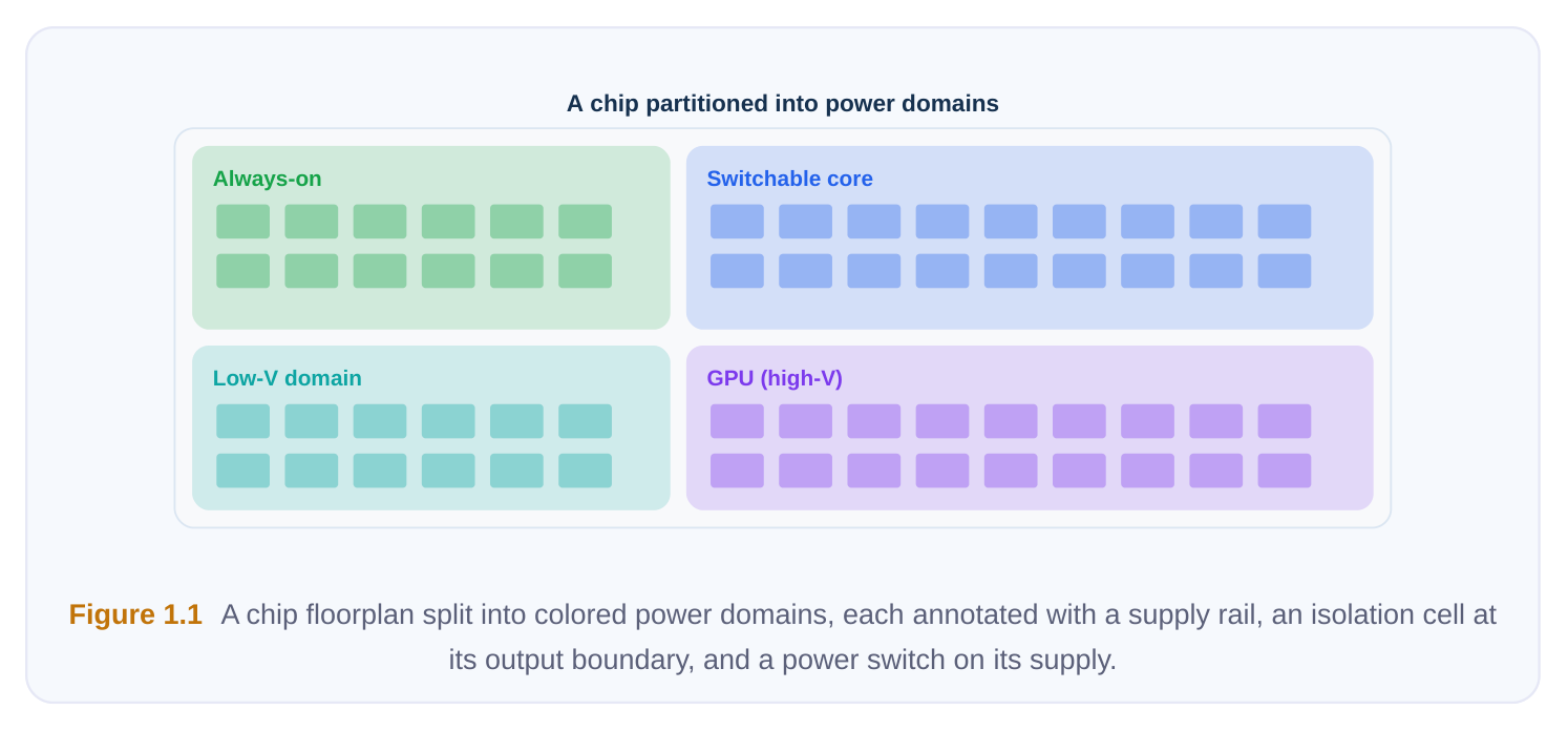
Modern systems-on-chip are not powered as a single, uniform block. They are partitioned into regions that can be switched off, dialed down to a lower voltage, or held at just enough voltage to remember their state while the logic around them sleeps. Expressing which regions behave how, and under which conditions, is the job of power intent. This chapter explains why that intent lives in a dedicated file separate from your RTL, what such a file actually declares, how the implementation tool ingests and applies it, and how the two open industry formats — CPF and UPF (IEEE 1801) — compare.
Why Power Intent Belongs in a Side-File
The instinct of a junior engineer is to bake low-power behavior into the RTL: instantiate the isolation gates, hard-code the switch enables, sprinkle in retention flops. This is exactly what you must not do. Power intent is captured in a separate side-file, read alongside the RTL and the netlist, for several concrete reasons. One source of truth. A single power-intent file is consumed by every stage of the flow — synthesis, place-and-route, static timing, equivalence checking, and verification. When all tools read the same description, they cannot disagree about where an isolation cell is required or what voltage a domain runs at. If the same facts were duplicated across RTL comments, scripts, and constraints, they would inevitably drift out of sync. Portability and tool independence. The RTL describes function; the side-file describes power architecture. Keeping them separate means the same RTL can target different libraries, different voltage strategies, or even different tools without being rewritten. Functional verification can run on clean RTL, while power-aware verification layers the intent on top. Machine-checkable. A structured, declarative file can be parsed, linted, and formally checked. Tools can confirm that every signal crossing from an off domain into an on domain is isolated, that every level shifter sits on a legal voltage pair, and that retention is specified for state that must survive a power-down. Comments in RTL cannot be checked this way. Early capture matters. Power intent should be authored before synthesis, not retrofitted after layout. The domain partition affects how logic is grouped; isolation and level-shifter rules affect cell selection; retention strategy affects flop choice and clock structure. Decisions made late force expensive rework
— re-synthesis, re-floorplanning, even re-architecting the supply network. Capturing intent early lets every downstream tool insert the right special cells in the right places the first time.
Realizing intent: PM-cell insertion
| Power intent | Match library | Insert & place | Tie controls & | Re-verify |
|---|---|---|---|---|
| (strategies) | PM cells | cells | supplies |
Figure 1.2 A horizontal flow — RTL plus power-intent side-file feeding synthesis, then P&R, STA, and verification,
with the same side-file fanning out to all four stages.
The Two Industry Formats at a High Level
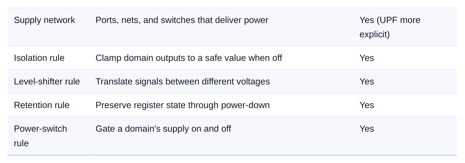
There are two open, standardized formats for describing power intent. Both are Tcl-based, both are vendor-readable, and — critically — both describe the same conceptual objects: power domains, supply networks, isolation rules, level-shifter rules, state-retention rules, and power-switch rules. An engineer fluent in the concepts can read either. CPF (Common Power Format) emerged from an industry coalition as an early, consolidated way to express power intent in a single command vocabulary. Its philosophy leans toward a relatively abstract, rule-driven description: you state high-level rules ("isolate the outputs of this domain when it powers down") and the tool maps them onto the supply implementation. UPF (Unified Power Format) was developed under an open standards body and later adopted as IEEE 1801, which is the formal, versioned standard most flows reference today. UPF's philosophy emphasizes an explicit supply network: you model supply ports, supply nets, and power switches as first-class objects and connect them deliberately, giving fine-grained control over exactly how power is routed and gated. Neither is "better." They reflect two design points on the same axis — abstraction versus explicit control. Because IEEE 1801 is an actively maintained international standard, it is the more common target for new designs, but plenty of mature flows and IP still ship CPF. A competent low-power engineer understands both and the one-to-one mapping between their concepts. A useful way to internalize the difference is to think about who decides where the supply nets run. In the more abstract, rule-driven style, you tell the tool the behavioral outcome you want and let it derive the supply connectivity that achieves it. In the explicit-network style, you yourself name every supply
port and net and wire them up — the tool honors what you wrote rather than inferring it. The first style is faster to author and harder to get subtly wrong at the boundaries; the second gives you precise, auditable control when the supply architecture is unusual (multiple always-on islands, nested switching, fine-grained retention). Most real flows end up using a blend of high-level rules for the common cases and explicit modeling for the tricky corners.
| Concept | What it means | Both formats? |
|---|---|---|
| Power domain | A group of instances sharing a primary supply and power | Yes |
behavior
What a Power-Intent File Declares
Regardless of format, a power-intent file declares four broad categories of information.
- 1. Power domains and PG connections. A power domain is a set of instances that share a primary
power/ground (PG) pair and a common power behavior. You declare each domain, the instances it contains, and how its supply nets connect to the cells' power and ground pins. This is the backbone everything else hangs from.
- 2. Operating conditions and analysis views. Low-power designs operate at multiple voltage/
temperature/process corners — and different domains may be at different voltages simultaneously. The intent (together with associated constraint files) defines the operating modes and the analysis views the tool must sign off across. A view ties a mode (a particular combination of domain voltages) to a corner so that timing and power are evaluated under realistic conditions. This matters enormously: a path that closes timing when both its source and sink domains run at high voltage may fail badly when one of them drops to a low-power voltage, and a path can only be safely declared "false" or "don't care" once you know the combinations of domain states in which it is actually exercised. The set of legal combinations is captured in a power-state (or supply-state) table, described below.
- 3. Low-power cell definitions. The flow needs to know which library cells are isolation cells, level
shifters, retention flops, power switches, and always-on buffers, plus their special pins (enable, save/ restore, switch control). These definitions let the tool legally insert and connect the special cells the rules call for.
4. Low-power rules. The behavioral heart of the file:
- Isolation — clamp the outputs of a domain that may be powered down so the receiving (still-on) domain never sees a floating value.
- Level-shifting — insert shifters wherever a signal crosses between domains at different voltages.
- State retention — preserve selected register state during power-down using retention cells driven by save/restore controls on an always-on supply.
- Power switching — define the switch network that connects or disconnects a domain's switchable supply, including the enable signal and acknowledge. Rule type Problem it solves Key controls Isolation Floating/unknown signals from an off Enable signal, clamp value, location domain Level shifter Voltage mismatch across a domain Source/sink voltage, direction boundary State Losing register contents on power-down Save signal, restore signal, retention supply retention Power switch Turning a domain's supply on/off Switch enable, ack, always-on control supply
Power-State Tables: Declaring Legal Combinations
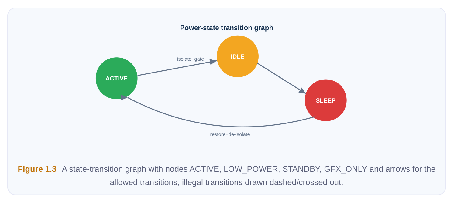
A design with several switchable domains has many possible supply combinations, but only some are legal. A power-state table (also called a supply-state table) enumerates the named system states and, for each, the state of every domain's supply. It is the contract that tells timing, power, and verification tools which combinations to analyze and — just as importantly — which to treat as illegal and ignore. Consider a simple SoC with an always-on domain, a CPU domain that can be switched off, and a GPU domain that can run at two voltages or be off:
| System state | Always-on | CPU domain | GPU domain |
|---|---|---|---|
| ACTIVE | ON (0.8 V) | ON (0.8 V) | ON (0.9 V) |
| LOW_POWER | ON (0.8 V) | ON (0.6 V) | OFF |
| STANDBY | ON (0.8 V) | OFF (retained) | OFF |
| GFX_ONLY | ON (0.8 V) | OFF | ON (0.9 V) |
Declaring these states does real work. It bounds the analysis views so the tool never wastes effort signing off a combination that can never occur, and it lets verification flag a transition the hardware permits but the architect never intended (for example, a path that would briefly leave a domain unisolated). Getting the table right early is part of "capturing intent early" — it shapes which corners you sign off and which low-power crossings need isolation.
Reading In and Committing the Intent
A power-intent file is declarative, but the implementation tool must turn those declarations into concrete actions on the design database. This typically happens in two conceptual steps: read and commit/apply. Reading parses the file and builds an in-memory model of domains, supplies, and rules, checking syntax and basic consistency. Committing (also called applying or building the power intent) resolves the rules against the actual design — figuring out exactly which nets cross domain boundaries, where isolation and level shifters are required, which flops become retention flops, and how the switch network attaches — so subsequent commands operate on a fully power-aware netlist.
# Generic, tool-independent style — names are illustrative
# 1. Load the design first
read_netlist   ./design/top.v
link_design    top
# 2. Read the power-intent side-file (CPF or UPF)
read_power_intent  ./power/top_intent.upf
# 3. Resolve rules against the design and make the
#    database power-aware
commit_power_intent
After the commit, queries and reports reflect the power architecture: you can list domains, ask which boundaries are isolated, or check that every cross-voltage path has a shifter.
# Inspect what was applied
report_power_domains
report_isolation        -domain pd_cpu
report_level_shifters   -from pd_cpu -to pd_soc
check_power_intent      ;# lint the resolved intent
Minor-change handling. Not every change requires re-reading the whole file. Two patterns are common:
- Intent ECO — a small change to the intent itself (add an isolation rule, change a clamp value, add an instance to a domain). You apply an incremental update so the tool inserts or modifies only the affected cells rather than rebuilding everything.
- View update — a change only to analysis conditions (a new corner, a tweaked operating voltage) leaves the rules untouched; you refresh the views and re-analyze without re-committing the power architecture. Knowing which bucket a change falls into saves enormous runtime and avoids needlessly perturbing an already-clean implementation.
Version Evolution and Interoperability
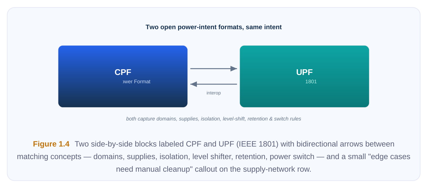
Both formats have evolved. Conceptually, early versions established the core object model — domains, supplies, the four rule families. Later revisions added richer supply-state and power-state tables (enumerating the legal combinations of domain voltages and which are illegal), more precise control over isolation/shifter placement and granularity, better support for hierarchical and IP-level reuse (so a block's intent can be packaged and instantiated in a larger design), and tighter semantics so different tools interpret the same file identically. The standardized format in particular advances through numbered releases of its governing standard; each release stays largely backward-compatible while adding expressiveness. As an interviewee, you don't need to memorize which feature landed in which revision — but you should know that powerstate/supply-state tables are the mechanism for declaring legal voltage combinations, and that newer revisions formalized them. Converting and interoperating. Because the two formats describe the same underlying concepts, automated conversion between them is feasible and tools/utilities exist to translate one into the other. Conversion is largely mechanical for the common cases: a domain maps to a domain, an isolation rule to an isolation rule. The friction lives in the edges — UPF's explicit supply-network objects don't always have a one-line CPF equivalent and vice versa, and idioms around always-on routing or switch modeling may need manual cleanup. Practical guidance: pick one golden format as your source of truth for a project and generate the other only when a specific tool or IP demands it, rather than maintaining two hand-edited copies.
Comparison Table of the Two Formats
| Dimension | CPF | UPF (IEEE 1801) |
|---|---|---|
| Origin | Industry coalition, early consolidated format | Open standards body; adopted as IEEE 1801 |
| Governance | Industry consortium specification | Formal, versioned international |
standard
| Base language | Tcl | Tcl |
|---|---|---|
| Philosophy | Abstract, rule-driven; tool maps rules to supplies | Explicit supply network as first-class objects |
| Supply modeling | More implicit / higher level | Explicit ports, nets, switches |
| Captures domains | Yes | Yes |
| Captures isolation / level | Yes | Yes |
shifter
| Captures retention | Yes | Yes |
|---|---|---|
| Captures power switching | Yes | Yes |
| Legal voltage | Supply/power state description | Power-state / supply-state tables |
combinations
Typical strength Concise, quick to author at a high level Fine-grained control, broad standard
| Best fit | Flows already standardized on it; some | New designs; multi-tool, standards- |
|---|---|---|
| legacy IP | driven flows |
Interview Q&A
destroys the separation between function and power architecture. Hard-coding low-power cells in RTL makes the RTL non-portable across libraries, voltages, and tools; it can't be machine-checked the way a structured intent file can; and it forces functional verification to wade through power plumbing. The side-file keeps one source of truth that every flow stage reads identically, and it lets tools insert the right cells automatically based on declared rules.
rules apply, and in what order do you think about them? Two rules apply. First, isolation — because the source domain can be off, its output must be clamped to a defined value so the always-on receiver never samples a floating net. Second, level-shifting — because 0.7 V and 0.9 V differ, the signal must be translated to the receiver's voltage. Conceptually you isolate the unknown-when-off condition and shift the voltage; many flows realize this with a combined isolation-plus-shift cell, but as intent you declare both an isolation rule and a level-shifter rule on that boundary.
matter? An intent ECO changes the power architecture itself — a new isolation rule, a domain membership change, a different clamp — so the tool must incrementally re-resolve and insert/modify special cells. A view update changes only analysis conditions — a new corner or operating voltage — leaving the rules and inserted cells untouched; you just refresh the views and re-analyze. It matters because treating a view change as a full re-commit wastes runtime and can needlessly disturb a clean netlist, while treating a real rule change as merely a view refresh leaves the design missing required cells.
handle it? The concepts map one-to-one, so I'd convert the CPF to UPF with an automated translation utility, then review the edges — particularly explicit supply-network and switch/always-on modeling, where CPF's higher-level idioms don't always translate cleanly — and fix those by hand. I'd keep the project's UPF as the single golden source and treat the converted file as generated, rerunning conversion if the IP updates rather than hand-maintaining two divergent copies. Finally I'd lint and formally check the merged intent to confirm isolation, shifting, and retention are all correctly expressed at the IP boundary.
Key Takeaways
- Power intent lives in a dedicated side-file, separate from RTL, to give one source of truth that is portable, tool-independent, and machine-checkable; capture it early, before synthesis, to avoid costly rework.
- A power-intent file declares four things: power domains and PG connections, operating conditions/ analysis views, low-power cell definitions, and the four low-power rules — isolation, level-shifter, state-retention, power-switch.
- The two open formats — CPF and UPF (IEEE 1801) — describe the same objects; CPF leans abstract and rule-driven, UPF models the supply network explicitly and is the actively maintained international standard.
- Intent is read then committed/applied to make the database power-aware; handle small changes as an intent ECO (rule change, incremental re-insertion) versus a view update (analysis conditions only).
- The formats are convertible because their concepts map one-to-one; keep a single golden format and generate the other only when a tool or IP requires it, cleaning up supply-network edge cases by hand.
Comments
Leave a Reply