 ChipBuddy
← Home
ChipBuddy
← Home
The MSV Bottom-Up Hierarchical Flow
Flow
When a chip is small enough, you can flatten everything into a single physical implementation run and let the placer and router see every gate at once. Modern low-power SoCs rarely give you that luxury. They are too large for a single tool session to handle in reasonable wall-clock time, they reuse hardened IP that arrives pre-built, and they are developed by several teams working in parallel against an aggressive schedule. The answer to all three pressures is the same: break the design into blocks, implement those blocks first, and then assemble the full chip around the finished pieces. That is the essence of the bottom-up hierarchical flow, and when each block carries its own multi-supply-voltage (MSV) and power-intent baggage, the integration step becomes the most interesting and most failureprone part of the whole project. This chapter explains how bottom-up implementation works for low-power designs, how blocks are abstracted into lightweight models for top-level use, how per-block power intent is rolled up into a coherent full-chip description, and where the approach wins and where it bites.
Bottom-Up Versus Top-Down: A Question of Who Goes First
Both flows are hierarchical; both eventually produce a placed, routed, full-chip database. The difference is ordering and who controls the budget. In a top-down flow, the chip is planned first. The top level owns the floorplan, the power grid, the voltage areas, and the timing budgets. Block boundaries, pin locations, and interface constraints are derived from that top-level plan and pushed down to the block teams as constraints. Blocks are then implemented to satisfy budgets they did not author. Integration is relatively painless because everyone built to a shared plan, but the top level becomes a bottleneck and nothing finishes until the plan is stable. In a bottom-up flow, the blocks go first. Each block is implemented to its own constraints and its own low-power intent, often before the top-level floorplan is finalized. Once a block is closed, it is reduced to an abstract (a compact model of timing, physical boundary, and power information) that the top level consumes. The top integrates these finished abstracts, builds the chip-level power network around them, and resolves whatever interface mismatches surface. Parallelism is excellent and reused IP slots in naturally, but the risk shifts to integration time, when conflicts between independently made decisions finally meet.
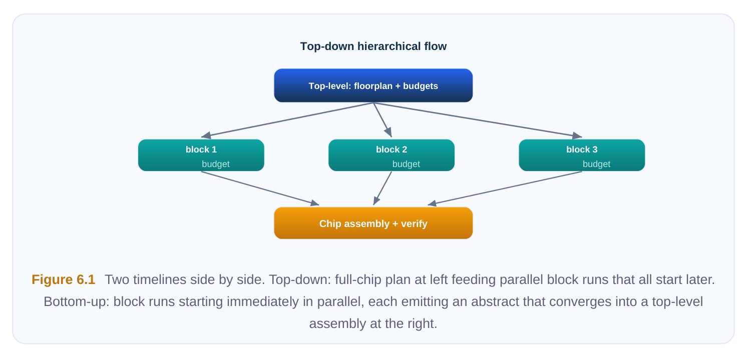
Most real projects are hybrid: an early top-level budgeting pass sets coarse floorplan and power-area targets (a top-down skeleton), then blocks are built bottom-up against those targets, then reintegrated. The pure forms are useful to reason about, but the hybrid is what ships.
Block-First Implementation
A block in a bottom-up flow is implemented almost as if it were a small chip. It has its own constraint set, its own clocks (or clock budgets at the boundary), its own power-intent file, and its own sign-off. Crucially, for an MSV design, the block declares internally which logic runs at which supply, which regions are switchable, and how its boundaries behave with respect to power.
The low-power objects you learned in earlier chapters - power domains, level shifters at voltage crossings, isolation cells on outputs that may go down, retention strategy on state that must survive a shutdown - are all defined and implemented inside the block. The block author owns them. The top level should not have to reach inside the block to insert a level shifter on an internal net; that would defeat the entire point of hierarchy. Two boundary disciplines make a block safely reusable at the top:
- Boundary supply clarity. Every block port must have a known voltage and a known domain association. If port
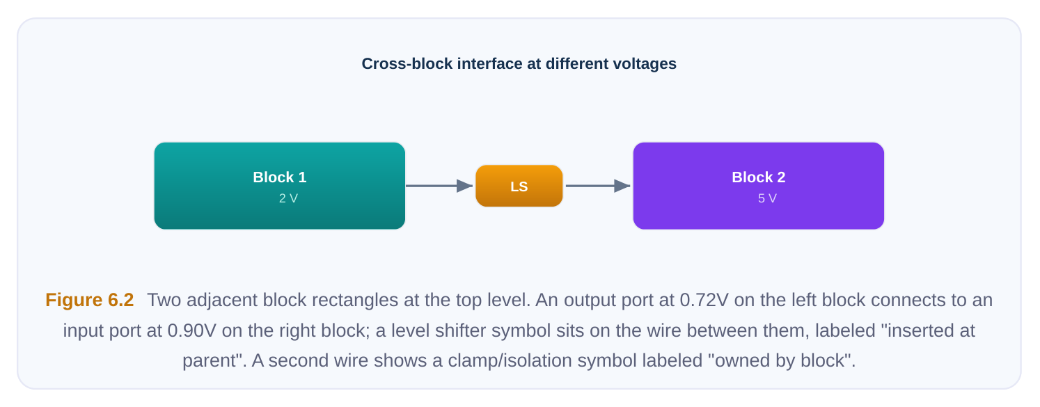
data_out[31:0]is driven by logic in a 0.72 V domain, the abstract must say so, because the consumer of that port at the top may sit in a 0.90 V domain and require a level shifter on the outside. - Boundary protection ownership. The block must declare whether isolation and level shifting at its ports are handled inside the block or expected to be added by the parent. Ambiguity here is the single most common source of integration bugs in MSV bottom-up flows.
# Block-level: declare the block's own power intent (UPF-style sketch)create_power_domain PD_COREcreate_power_domain PD_ALWAYS_ON -elements {ctrl_regs lvshift_ctl}create_supply_port VDD_COREcreate_supply_port VDD_AONcreate_supply_net VN_CORE -domain PD_COREcreate_supply_net VN_AON -domain PD_ALWAYS_ON# State that must survive a core shutdown lives in the AON domainset_retention RET_CORE -domain PD_CORE \-retention_supply VN_AON# Outputs that may float when PD_CORE is off get isolation, owned by the blockset_isolation ISO_CORE -domain PD_CORE \-isolation_supply VN_AON -clamp_value 0 \-applies_to outputsNote that retention and isolation here are the block's decisions, recorded in the block's intent file. The top level will later need to know that these exist, but it will not re-author them.
Abstracting the Block
Once a block is closed - placed, routed, timing-clean, DRC-clean, and power-verified - it is too heavy to drag into the top-level session in full detail. A 50-million-instance block would swamp the top tool if loaded as flat gates. Instead the block is reduced to an abstract: a model that exposes only what the top level needs and hides everything else. A good MSV block abstract carries three kinds of information:
Abstract
What it captures Why the top needs it
| Timing model | Boundary arrival/required times, setup/hold at | Lets the top close timing across the |
|---|---|---|
| ports, internal path delays collapsed to port-to- | interface without re-analyzing block port arcs | internals |
| Physical | Block outline, pin/port locations and layers, | Lets the top place, route, and connect |
| abstract | blockages, internal power-grid connection points | the grid around the block as a black |
box
| Power/ | Port voltages, domain associations, supply pin | Lets the top compose power intent and |
|---|---|---|
| boundary | locations, isolation/level-shift expectations | insert any external protection correctly |
model The timing model is the classic interface timing abstraction: internal paths are reduced to contextindependent (or lightly context-dependent) port arcs so the top sees a small, fast model instead of millions of gates. The physical abstract is the geometric shell plus the grid attach points. The power model is the part that bottom-up MSV flows live or die on - it must state every port's voltage and domain, and it must declare the protection contract at the boundary.
# After block closure: emit the abstracts for top-level consumption
write_timing_model   -format lib   pd_core_block.lib
write_physical_model -format lef   pd_core_block.lef
write_power_model    -format upf   pd_core_block_macro.upf
# The power model exposes ports + domains as a black box,
# without leaking internal nets:
#   VDD_CORE @ 0.72V  -> drives data_out[*]   (domain PD_CORE)
#   VDD_AON  @ 0.90V  -> drives ctrl_status   (domain PD_ALWAYS_ON)
#   outputs of PD_CORE are isolated INSIDE the block
Why Abstracts Speed Top-Level Closure
The payoff is mostly about scale and repetition. Three concrete effects:
- 1. Capacity. Loading abstracts instead of flat gates can shrink the top-level database by one to two
orders of magnitude. The top session fits in memory and the placer/router actually finish.
- 2. Runtime. Timing analysis at the top traverses small port-to-port arcs rather than deep internal
paths, so each iteration is dramatically faster - and you iterate a lot at the top.
- 3. Stability. A frozen abstract is a contract. As long as the block does not change, the top can iterate
without re-validating block internals. When a block respins, you regenerate its abstract and only the interface needs re-checking. The cost is abstraction fidelity. An abstract is a lossy summary. If the timing model omits a context the top later creates, or the power model understates the boundary protection needed, the top will close
on a lie and the error surfaces only at full-chip sign-off. Good teams treat abstract generation as a firstclass deliverable with its own review, not an afterthought.
Top-Level Assembly Around Finished Blocks
At the top, the blocks are already physical realities. The full-chip floorplan is built around them: you place the block abstracts, define the chip-level voltage areas that contain them, and build the power network so that every block's supply pins are fed by the right grid at the right voltage. The order is roughly:
- 1. Place the blocks. Block outlines and their supply-pin locations drive chip floorplanning. You cannot
freely move a hardened block's pins, so the grid must come to them.
- 2. Build the chip power grid. Top-level rails and straps must align to the block grid attach points
exposed by the physical abstract, at each required voltage. MSV means multiple rails coexisting and being kept apart where they must not touch.
- 3. Insert top-level protection. Where a block output at one voltage feeds a block input at another,
the top inserts the external level shifter or isolation that the block declared it does not own.
- 4. Close top-level timing and verify power intent. Interface timing uses the block timing models;
power verification confirms the composed intent is self-consistent.
# Top-level: instantiate block abstracts and feed their supplies
create_voltage_area VA_DSP   -coordinate {x1 y1 x2 y2} \
-instances {u_dsp}        ;# u_dsp is the PD_CORE block abstract
# Chip rails at the two voltages used across the SoC
create_supply_net VN_0P72 -domain TOP
create_supply_net VN_0P90 -domain TOP
# Connect the block's supply ports to the matching chip rails
connect_supply_net VN_0P72 -ports {u_dsp/VDD_CORE}
connect_supply_net VN_0P90 -ports {u_dsp/VDD_AON}
# External level shifter where a 0.72V block output crosses
# into a 0.90V consumer at the top
set_level_shifter LS_DSP2MEM -domain TOP \
-applies_to outputs -location parent \
-threshold 0.10 -rule low_to_high
The phrase to internalize is location parent: this protection lives at the parent (top) level precisely because the block declared it would not handle that crossing. Getting location wrong - block thinks parent owns it, parent thinks block owns it - produces either a missing shifter (functional failure) or a double shifter (area and timing waste).
Resolving Interface Mismatches
Bottom-up integration is, in practice, a mismatch-hunting exercise. The common classes:
- Voltage mismatch. A port driven at one voltage feeds a consumer expecting another, with no shifter on either side. Fix: insert at the agreed location, or respin one block's boundary.
- Protection-ownership mismatch. Both sides assume the other inserts isolation, so none exists; or both insert it. Fix: settle ownership in the abstract contract.
- Pin/grid mismatch. The block's supply pins do not align to the chip grid pitch the top wants. Fix: route a stitching layer, or re-plan the grid - this one is expensive late.
- Budget mismatch. The block met its boundary timing budget, but the top's realized interconnect is longer than the budget assumed. Fix: re-budget and re-close the block, or absorb at the top.
Power-Intent Composition
The single most important low-power activity at integration is composing the per-block power intent into one consistent full-chip intent. Each block ships a power model describing its domains, supplies, and boundary protection. The top must roll these up so the chip-level view is complete and contradiction-free. Two mental models help. First, each block's intent is a namespace that the top instantiates - the block's PD_CORE becomes u_dsp/PD_CORE at the top, and its VDD_CORE port must be tied to a real chip supply. Second, the top adds only the inter-block objects: the external shifters, the chip-level voltage areas, and the supply connections. It should not redefine what the block already defined. Consistency checking at integration must confirm:
| Check at integration | Failure if violated |
|---|---|
| Every block supply port is connected to a chip supply net | Floating supply; block has no power source |
| Connected rail voltage matches the port's declared voltage | Wrong-voltage operation, reliability/ |
functional failure
Every voltage crossing has exactly one protection cell at the Missing or duplicated level shifter / isolation
| Block-declared isolation enables are driven by valid control at | Isolation never asserts; floating values |
|---|---|
| the top | propagate |
| Composed domain states (power state table) are reachable | Illegal simultaneous on/off combinations |
and conflict-free
# Top-level: compose and check the rolled-up intent
load_upf pd_core_block_macro.upf -instance u_dsp   ;# pull in block intent
load_upf pd_gfx_block_macro.upf  -instance u_gfx
# Add only the inter-block objects at the top
connect_supply_net VN_0P72 -ports {u_dsp/VDD_CORE u_gfx/VDD_CORE}
connect_supply_net VN_0P90 -ports {u_dsp/VDD_AON  u_gfx/VDD_AON}
# Roll-up consistency / structural power-intent check
check_power_structure -hierarchical -report cpf_upf_compose.rpt
When this check is clean, the composed UPF (or CPF) is a faithful full-chip description: every domain has a defined supply, every crossing is protected once, and the power state table describes only legal combinations. When it is dirty, it is far cheaper to fix here than after detailed routing.
Top-Down Versus Bottom-Up: Comparison
| Dimension | Top-down | Bottom-up |
|---|---|---|
| Who owns budgets first | Top level defines and pushes down | Blocks author their own, top |
reconciles later
| Parallelism | Limited - blocks wait on the top plan | High - blocks proceed independently |
|---|---|---|
| Control over global | Strong and early resources (grid, areas) | Weaker; grid bends around finished blocks |
| Integration risk | Low - shared plan | High - conflicts surface late |
| Reuse of hardened/3rd-party | Awkward (IP predates your plan) | Natural (IP is already an abstract) |
IP
| Best when | Tightly coupled blocks, evolving | Mature/reused blocks, parallel teams, |
|---|---|---|
| partitioning, one team | stable partitioning | |
| Main hazard | Top-level bottleneck stalls everyone | Late interface/budget churn forces |
respins
When Bottom-Up Wins, and When It Hurts
Bottom-up is the right call when blocks are mature or reused (a hardened memory subsystem, a licensed core, a previous-generation block) and when multiple teams must work in parallel against a schedule. In those situations the abstract-and-assemble model is not just convenient, it is the only way the project fits in the calendar. Reused IP is already in abstract form, so the flow matches reality. It hurts when partitioning is still in flux or blocks are tightly coupled. The characteristic bottom-up failure is late discovery: a voltage or protection-ownership conflict, or a boundary budget that was optimistic, that nobody could see until the finished blocks met at the top. By then the blocks are hardened, so the fix is a respin and the schedule benefit you bought with parallelism is partly refunded as integration churn. The defenses are an early top-level budgeting pass (the hybrid skeleton), strict boundary contracts in the abstracts, and running the power-intent composition check as early and as often as possible - ideally before blocks are fully hardened, so conflicts are caught while they are still cheap to change.
Interview Q&A
inside the block or at the top? It depends on the declared ownership contract, and the key requirement is that the contract is unambiguous. A common convention: the block protects its own internal crossings, while crossings between blocks (different blocks at different voltages) are inserted at the parent using a location parent strategy. What you must avoid is both sides assuming the
other handles it (missing shifter, functional failure) or both inserting one (wasted area and delay). The block's power abstract should state explicitly which boundary protection it owns.
abstract carries a timing model (port-to-port arcs and boundary constraints), a physical model (outline, pin locations/layers, blockages, grid attach points), and a power/boundary model (port voltages, domain associations, supply pins, protection contract). You do not load the full block because capacity and runtime would explode - flat gates can be one to two orders of magnitude larger - and because a frozen abstract is a stable contract that lets the top iterate without re-validating block internals. The trade-off is abstraction fidelity: a lossy model can hide a context that later breaks at sign-off.
power model (UPF or CPF). At the top, you instantiate each block's intent under its instance name, connect every block supply port to a real chip supply net at the correct voltage, and add only the interblock objects - external shifters, chip-level voltage areas, supply connections. Then you run a hierarchical power-structure check to confirm no floating supplies, no voltage-rail mismatches, exactly one protection cell per crossing, valid isolation control, and a conflict-free power state table. You compose and check; you do not re-author what the block already defined.
preferable when blocks are tightly coupled, the partitioning is still evolving, or you need firm early control over global resources like the power grid and voltage-area placement. Because the top defines budgets first, integration is low-risk and consistent. The cost is parallelism: blocks wait on a stable top plan, so the top becomes a bottleneck. Bottom-up wins the opposite case - mature/reused IP and parallel teams - at the cost of late-surfacing interface and budget conflicts. Most projects blend the two: a top-down budgeting skeleton followed by bottom-up block builds.
Key Takeaways
- Bottom-up means blocks first, top last. Blocks are implemented to their own constraints and low-power intent, then abstracted; the top assembles around finished blocks. Top-down reverses ownership: the top plans and pushes budgets down.
- The abstract is the unit of exchange. Timing model + physical model + power/boundary model let the top treat a block as a fast, compact black box and iterate without re-validating internals.
- Boundary contracts are everything in MSV. Every port needs a known voltage and domain, and protection ownership (who inserts level shifters/isolation) must be unambiguous.
location parentvs. block-owned is a frequent bug source. - Power intent is composed, not rewritten. Instantiate each block's intent, connect supplies at the right voltage, add only inter-block objects, then run a hierarchical consistency check before detailed routing.
- Bottom-up trades integration risk for parallelism. It wins for mature/reused blocks and parallel teams; it hurts via late-discovered conflicts. Defend with an early budgeting skeleton, strict abstract contracts, and early-and-often composition checking.
Comments
Leave a Reply