 ChipBuddy
← Home
ChipBuddy
← Home
Low-Power Cells and Their Role in the Flow
In Chapter 1 we built the conceptual scaffolding: power domains, supply nets, operating states, and the intent files (CPF and the IEEE 1801 UPF standard) that describe them. This chapter is about the physical hardware that enforces that intent. When you partition a chip into independently controllable supplies, you create electrical hazards at every seam between domains and every transition in time. Special standard cells exist precisely to neutralize those hazards. The mark of an engineer who has actually closed a multi-voltage design—as opposed to one who has only read about it—is knowing not just what each cell does, but where in the flow it appears, what triggers it, what extra pins it carries, and how it constrains placement and routing. That is the lens for this entire chapter. Think of the intent file as a contract. Each clause—an isolation strategy, a level-shift rule, a retention requirement—is a promise that the implementation tool must keep. A low-power cell is how the tool keeps that promise in silicon. Our job is to trace each clause from its declaration through synthesis, placement, and routing.
The Catalog at a Glance
Before the deep dives, here is the master reference. Everything that follows expands on one of these rows.
| Cell type | Purpose | Trigger condition | Special pins | Stage inserted |
|---|---|---|---|---|
| Isolation | Hold a domain | Output of a | Isolation enable; | Inserted during |
| cell (clamp) | crossing at a known logic value when | domain that powers down the driver is off | secondary always-on PG feeds a domain that stays on | synthesis or a dedicated low-power insertion step; placed pre-/post-CTS |
| Level | Translate a signal | Signal crosses | Both primary supplies | Inserted at the |
| shifter | between two different voltage | from one voltage domain to another rails | (and well/ground refs); sometimes an enable | boundary, typically during synthesis/low- power insertion; placed |
near crossing
| State- | Preserve register | Register lives in a | Save, Restore (or a | Mapped during |
|---|---|---|---|---|
| retention | state while the main | switchable domain | single retention | synthesis; placed and |
| flop | supply collapses (SRPG) | that must wake with prior state | control); secondary always-on PG | tied to retention controls before routing |
| Power | Connect or | A domain is | Switch enable | Inserted during |
| switch | disconnect a | defined as power- | (sleep); acknowledge/ | placement (switch |
| (header/ | domain's switched | gatable footer) | out; true and switched supply from the | planning); routed early supply |
permanent rail
| Always-on | Drive control nets | A control signal | Secondary always-on | Inserted during |
|---|---|---|---|---|
| buffer | through a powered- down region without | must remain live inside a collapsed | PG separate from local supply losing them | placement/routing of always-on nets domain |
| Tie cell | Provide a constant | A constant is | Primary PG matching | Inserted late, during |
| (gated- | logic 1/0 sourced aware) | needed inside a from the correct, | the consuming gated or specially- valid supply | placement/optimization domain supplied domain |
Isolation Cells (Clamps)
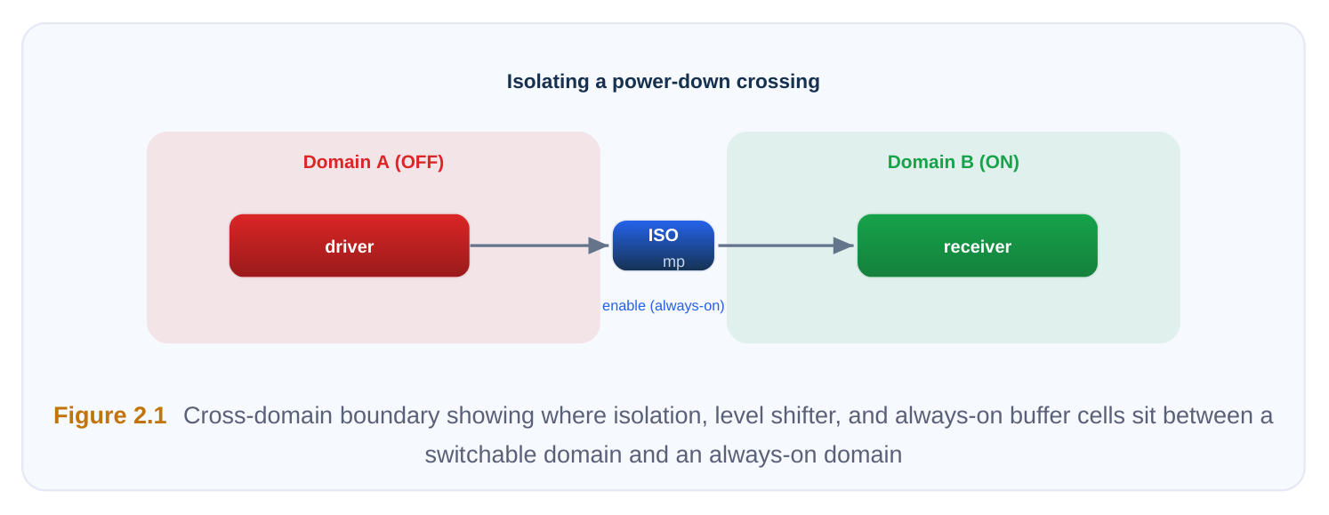
Its job. When a power domain shuts down, its outputs float to an undefined, intermediate voltage. If those outputs drive logic in a domain that is still active, that intermediate voltage can cause crowbar current, metastability, or simply garbage data. An isolation cell sits on the crossing and clamps the signal to a defined value—often a logic 0 (an AND-style clamp), a logic 1 (an OR-style clamp), or the last latched value (a latch clamp)—whenever the source is off. The trigger condition. Isolation is required on any net that leaves a domain which can power down and enters a domain that remains powered in that same state. Note the asymmetry: a crossing from an always-on domain into a switchable one usually needs no isolation, because the always-on driver is never undefined. The direction matters, and a common review item is confirming isolation is placed on
the correct side of the boundary—conventionally on the destination/receiver side so the wire carrying an unknown value is as short as possible, though the source side is sometimes chosen for floorplan reasons. Special pins. The defining pin is the isolation enable. This control is asserted by the power management logic before the source domain collapses and de-asserted only after it has reliably restored. Critically, the isolation cell and its enable net must themselves be powered when everything around them is off—so the cell carries a secondary always-on power-ground (PG) connection distinct from the (now dead) primary supply of the region it sits in. Stage and physical implications. Isolation cells are inserted when the isolation strategy is elaborated—during synthesis or a dedicated insertion pass. Physically, two rules dominate. First, the enable net is an always-on signal and must be routed on a supply that survives the shutdown; a buffered enable that gets buffered with ordinary cells in the dead region is a classic bug. Second, the cell needs its secondary PG hooked up, which means the always-on rail must reach wherever the isolation cell is placed. Common mistakes. Placing isolation on a net that crosses into a powered-down domain (wasted area, no benefit); using a clamp value that violates downstream assumptions (a 0-clamp into an active-low reset can trigger a spurious reset); forgetting that the enable must be valid across the entire shutdown window; and letting the tool buffer the enable with non-always-on cells.
Level Shifters (Up, Down, Dual-Rail)
Its job. Two domains running at different voltages cannot simply share a wire. A signal driven at 0.7 V into a gate expecting 0.9 V logic levels may never register as a valid high; a 0.9 V signal into 0.7 V logic can forward-bias protection diodes. A level shifter rebuilds the signal at the destination's voltage. The trigger condition. Any signal crossing between domains whose voltages differ. Up-shifters (low to high) and down-shifters (high to low) have different internal topologies; down-shifting is electrically easier and sometimes achievable with a buffer, while up-shifting almost always needs a true dual-rail structure. A dual-rail (enable-style) level shifter combines shifting with isolation—it both translates voltage and clamps when enabled—useful where a crossing both changes voltage and spans a power-gated boundary. Special pins. A level shifter connects to two primary supplies: the input-side rail and the output-side rail (plus shared or separate ground). The enable-type variant adds an isolation enable. Getting both PG pins connected to the correct nets is the entire game. Stage and physical implications. Inserted at the boundary during synthesis/low-power insertion. The non-negotiable physical rule is placement location: a level shifter must be placed in a region where both of its supplies are legally available, or in whichever domain the methodology designates (commonly the higher-voltage side for up-shifters). Place it in the wrong row and the second rail simply is not there. Many flows reserve boundary placement regions or special rows for this reason.
# Generic level-shifter rule declaration (UPF-style)
set_level_shifter ls_core_to_io \
-domain  PD_IO \
-applies_to outputs \
-location  parent \
-rule      low_to_high
# Down-shift crossing the other direction
set_level_shifter ls_io_to_core \
-domain  PD_CORE \
-applies_to inputs \
-location  self \
-rule      high_to_low
Common mistakes. Missing a shifter on a path the tool did not flag because the voltages were declared equal but implemented differently; placing the cell where the second supply is absent; using a plain down-buffer where margin actually demands a real shifter; and double-inserting both a separate isolation cell and an enable-type shifter on the same net.
State-Retention Flops (SRPG)
Its job. A state-retention power-gated (SRPG) flop preserves its stored value through a power-down of the main supply. Internally it is an ordinary flip-flop paired with a tiny balloon latch (a shadow storage element) that lives on the always-on supply. Before shutdown the main value is copied into the balloon; on wake it is copied back. This lets a domain power down completely yet resume exactly where it left off—far faster and lower-energy than reloading state from elsewhere. The trigger condition. Used when a switchable domain must retain specific register state across power-down. Retention is expensive in area and always-on leakage, so it is applied selectively—often only to configuration, mode, and a small amount of control state, not bulk datapath pipelines. Special pins. The retention controls: save (capture into the balloon) and restore (write back), sometimes merged into a single retention/clamp signal with defined polarity. The balloon storage is fed by a secondary always-on PG so it survives while the primary supply collapses.
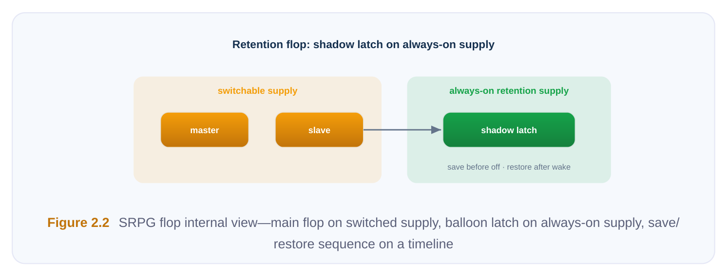
Stage and physical implications. SRPG cells are mapped during synthesis (the tool substitutes them for ordinary flops per the retention strategy), then placed and connected before routing. Physically: the save/restore controls are always-on nets with their own timing requirements relative to the power-switch acknowledge, and the cell needs its secondary PG routed. Because retention controls fan out widely, their buffering must use always-on cells and is often balanced like a low-skew network.
# Generic retention strategy
set_retention rtn_pd_cpu \
-domain        PD_CPU \
-save_signal   {pmu/save_n  negedge} \
-restore_signal {pmu/restore_n posedge} \
-retention_power_net  VDD_AON
Common mistakes. Retaining far more registers than necessary (leakage and area blow-up); a save/ restore sequence that violates the required ordering against the switch acknowledge; routing the retention controls on the switched supply by accident; and forgetting that some logic not retained needs reset on wake to avoid mixing stale and fresh state.
Power Switches (Header / Footer)
Its job. A power switch is the gate that connects a domain's local switched supply to the permanent rail. A header switch (PMOS-based) sits between the true VDD and the domain's virtual VDD; a footer switch (NMOS-based) sits between the domain ground and true ground. Turn it off and the domain's supply collapses, killing leakage; turn it on and the domain wakes. The trigger condition. Present in any domain declared power-gatable. Switches are not a single big device but typically an array of many small switch cells distributed across the domain so the supply can be re-energized without excessive rush current. Special pins. The sleep/enable input that commands on/off; an acknowledge (ack) output on some styles, used by the controller to confirm the supply is stable; and of course the true supply and switched (virtual) supply terminals. Stage and physical implications. Switch insertion happens during placement (switch planning), early, because switches define the power grid of the gated domain and consume real area. Two physical concerns dominate. First, in-rush current: switching the whole array on at once causes a current surge that can droop the rail, so the enable is daisy-chained (or staged) so switches turn on sequentially—the enable propagates cell to cell, and the final ack confirms the tail of the chain is on. Second, switch distribution and density must be uniform enough to keep virtual-rail IR drop acceptable when the domain is active.
# Generic power-switch / power-gating intent
create_power_switch sw_pd_gpu \
-domain        PD_GPU \
-output_supply_port {vout VDD_GPU_SW} \
-input_supply_port  {vin  VDD} \
-control_port  {sleep  pmu/gpu_sleep} \
-ack_port      {ack    pmu/gpu_ack} \
-on_state      {on  vin {!sleep}}
Common mistakes. Under-provisioning the switch array (excess IR drop, slow wake, failure to actually turn on); a broken or unbalanced daisy chain (in-rush spikes or an ack that never arrives); placing switches non-uniformly so part of the domain droops; and mismatching header-vs-footer choice to the library actually available.
Always-On Buffers
Its job. Some nets—isolation enables, retention save/restore, switch sleep controls, and signals that merely pass through a region geographically—must stay alive even where the local supply is dead. An always-on buffer is a buffer whose internal logic is powered from a secondary always-on PG, independent of the surrounding domain's switched supply. It keeps these critical controls driven through the blackout. The trigger condition. Any net that must function inside, or physically route across, a domain that can power down. The classic case is a control net generated by the power controller that has to reach an isolation cell sitting deep inside the region being shut off. Special pins. The differentiator is the secondary always-on supply pin, distinct from the cell's nominal rail. Functionally it is just a buffer; electrically it is a survivor. Stage and physical implications. Inserted during placement and routing of always-on nets. The whole point is physical: these buffers can be placed inside a switchable domain yet must tap the always-on rail, so the always-on supply must physically reach them—often via a dedicated always-on grid or rail woven through the domain. Engineers usually mark these nets explicitly so ordinary optimization never re-buffers them with normal cells. Common mistakes. The single most common low-power bug: the tool buffers an always-on net with an ordinary buffer that dies during shutdown, breaking the control. Others: failing to extend the alwayson rail to where the buffer lands; and over-using always-on buffers, which adds permanent leakage.
Tie Cells for Gated Domains
Its job. Logic often needs hard constants—a tie-high or tie-low source. Tying directly to a rail is discouraged for reliability; instead a tie cell provides a clean, controlled logic 1 or 0. In a multi-supply design the subtlety is which supply sources that constant. The trigger condition. A constant is needed inside a gated or specially-supplied domain. A tie cell drawn from the wrong supply produces an invalid constant when that supply is gated or sits at a
different voltage—so the constant must come from a tie cell powered by the consuming domain's (or an appropriate always-on) supply. Special pins. Just the primary PG, but it must match the domain that consumes the constant. There is no enable. Stage and physical implications. Inserted late, during placement and optimization, when constants are resolved. The physical rule is locality: the tie cell must be placed within—and powered by—the same supply region as its load, so a powered-down or differently-supplied region does not feed an invalid constant across a boundary (which would itself then demand isolation or shifting). Common mistakes. A single tie cell feeding loads across multiple domains; tie cells left on the wrong supply after domain edits; and constants that should have crossed through isolation/level-shift logic but instead were tied locally to an inappropriate rail.
How the Tool Knows Which Library Cell Realizes Each Rule
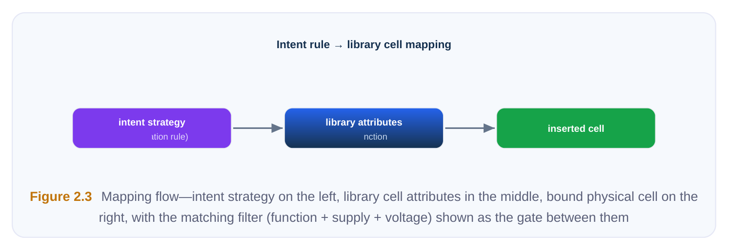
A strategy in the intent file is abstract—"isolate these outputs to 0." The tool must bind it to a concrete library cell. That binding rests on cell function attributes declared in the library: each special cell is tagged with what it is. The library marks a cell as an isolation cell with a given clamp value and identifies its enable pin; marks a level shifter with its direction and which pin is the input vs. output rail; marks a retention flop and names its save/restore pins; marks a power switch and names its enable, ack, and supply terminals; marks always-on cells and tie cells with their supply expectations. The tool then matches the function required by the strategy to cells carrying the matching attribute, filtered by the supplies and voltages in play. This is why a missing or wrong library attribute is so insidious: the cell physically exists but the tool cannot recognize it, so it either errors out or silently skips the rule.
# Generic identification / declaration of special cells to the flow
identify_power_logic -type isolation \
-cells {ISO_AND_X1 ISO_AND_X2} -enable_pin EN
identify_power_logic -type level_shifter \
-cells {LSHL_X1 LSHL_X2} -direction low_to_high \
-input_supply_pin VDDL -output_supply_pin VDDH
identify_power_logic -type retention \
-cells {DFFR_X1} -save_pin SAVE -restore_pin RESTORE \
-retention_supply_pin VDDC
# Sanity check: report what the tool believes about the library
report_power_logic -unmatched_strategies
The companion diagnostic—reporting strategies that found no matching cell—is one of the first things to run after reading the libraries. An unmatched isolation or shifter strategy is a guaranteed downstream failure.
Putting Stage Ordering Together
It helps to see the cells along the timeline of the flow rather than as a flat list.
| Flow stage | Cells that enter here | Why this stage |
|---|---|---|
| Library/setup | All—via function attributes | Tool learns what each cell is before any insertion |
| Synthesis / low-power | Isolation, level shifters, | These follow logical/boundary intent and affect |
| insertion | SRPG mapping | timing budgets early |
| Placement (switch | Power switches planning) | Switches define the gated power grid; needed before detailed placement |
| Placement / | Tie cells, some isolation/ | Constants and final sizing resolve with real |
| optimization | shifter sizing | locations |
| Routing of special nets | Always-on buffers; secondary PG hookup | Enable/save/restore/sleep nets and always-on rails are physical-only concerns |
The throughline: logical-boundary cells appear early; physical-survival cells appear late. Isolation and level shifting follow the netlist's boundaries and must be in the timing picture early. Power switches shape the grid, so they come at placement. Always-on buffering and secondary-PG connection are fundamentally about which wire survives, so they belong to routing.
Interview Q&A
doesn't have one? Because its entire purpose is to produce a valid clamp value while the surrounding domain is dead. If the isolation cell were powered only by the local switched supply, it would collapse at exactly the moment it is supposed to be holding the boundary, and the destination domain would again see an undefined input. The secondary always-on PG keeps the clamp logic and its enable alive through the blackout. Without it, you get the very floating-node hazard the cell was inserted to prevent.
cell(s) do you need, and where do you place it? This crossing both changes voltage (down-shift)
and spans a power-gated boundary, so you need both functions: either a separate down-shifter plus an isolation cell, or a single enable-type (dual-rail) level shifter that shifts and clamps together. Placement must satisfy supply availability—the cell must sit where both relevant rails (and the alwayson supply feeding the enable) are legally present, typically on the boundary in the domain the methodology designates. The enable must be an always-on net buffered only with always-on cells.
domain's supply is reconnected, the discharged virtual rail and its decoupling capacitance draw a large transient current to recharge. If the whole switch array turns on simultaneously, that surge droops the real rail and can disturb neighboring active logic. Switch cells manage it by staging turn-on: the enable is daisy-chained so switches activate sequentially, spreading the current over time. The acknowledge output at the end of the chain confirms the tail switch is on and the rail has settled before the controller releases isolation and restores state.
isolation strategy, and how would you debug a strategy that produced no cells? The tool relies on function attributes declared in the library—tags identifying a cell as retention, isolation, level shifter, etc., along with its special pins and supply expectations. It matches the strategy's required function against cells carrying that attribute, filtered by the supplies and voltages involved. If a strategy yields no cells, first run the report of unmatched strategies, then check that the library actually contains a cell of that function with the right clamp value/direction/voltage, that its attributes and special-pin names are declared, and that an available cell's supplies match the domains in the strategy. Almost always it is a missing/wrong attribute or a supply/voltage mismatch—not a true absence of hardware.
Key Takeaways
- Each low-power cell exists to neutralize a specific hazard created by independent supplies: floating crossings (isolation), voltage mismatch (level shifters), lost state (SRPG), leakage (power switches), dead control nets (always-on buffers), invalid constants (tie cells).
- The defining detail of most low-power cells is a secondary always-on PG—it is what lets a cell function while everything around it is off. Forgetting to route it is a top-tier bug.
- Where a cell enters the flow follows its nature: boundary-logic cells (isolation, level shifters, SRPG) are mapped/inserted early at synthesis; the power-grid cell (switches) enters at placement; survival-of-control cells (always-on buffers, secondary-PG hookup) are resolved at routing.
- Control nets—isolation enables, save/restore, switch sleep—are always-on signals and must be buffered only with always-on cells; never let ordinary optimization touch them.
- The tool binds abstract strategies to real cells through library function attributes; an unmatched strategy is almost always a library/attribute or supply/voltage problem, so report unmatched strategies right after reading the libraries.
- Direction and location are not bookkeeping—they are correctness: isolation belongs on the right side of the boundary, level shifters only where both supplies exist, tie cells only on the consuming domain's supply.
Comments
Leave a Reply