 ChipBuddy
← Home
ChipBuddy
← Home
Power Shutdown Techniques
If you remember only one number from a low-power interview, make it this one: leakage scales with the area that is powered on. Clock gating saves dynamic power, multi-Vt swaps and voltage scaling trim both dynamic and leakage, but none of them can take a block to zero. The only technique that does is to physically remove the supply from a block that has nothing to do. Cut the rail, and leakage in that block collapses to the sub-pico-amp noise floor of the off-state switch transistors. That is why power shutdown, also called power gating or building a switchable power domain, is the heaviest hammer in the low-power toolbox — and the one most likely to break your design if you swing it carelessly. This chapter assumes you already know the supporting cells from earlier chapters. We recap them briefly, then spend our time on the part that actually fails sign-off: the methodology of preparing, verifying, and sequencing a shutdown.
Why Shutdown Wins, and What It Costs
Consider a block that idles 90% of the time — a video codec, a modem accelerator, a debug fabric. Even with aggressive clock gating its registers, clouds of combinational logic, and memories sit on a live rail, bleeding leakage every nanosecond. Power-gate it and during the idle window that block contributes nothing. Over a realistic duty cycle this can erase 30–60% of a chip's total leakage budget. The cost is complexity. To switch a domain off and bring it back without corrupting the rest of the chip, you must add structure and obey ordering. Skip a step and you get one of the classic failures: a
floating input crowbarring a live gate, a lost configuration register, an inrush spike that browns out a neighbor, or a wake sequence that releases logic before its supply has settled. There is also a steady-state overhead worth naming up front. The switch transistors themselves are not free: even when fully on they drop a small IR voltage across the virtual rail, which eats into your timing margin in the active state. The switches consume silicon area — often several percent of the gated block — and their distribution affects how evenly the virtual rail charges. Retention flops are larger and slower than ordinary flops. Isolation cells add a logic stage in the signal path. None of this is a reason to avoid shutdown; it is a reason to scope it deliberately. You power-gate the blocks where the leakage-when-off savings dwarf the always-present overhead, and you leave small, latency-critical, or rarely-idle logic alone. A good architect treats "should this domain even be switchable?" as a firstclass question, answered with a duty-cycle and leakage model before any cells are placed.
Recap: The Supporting Cells
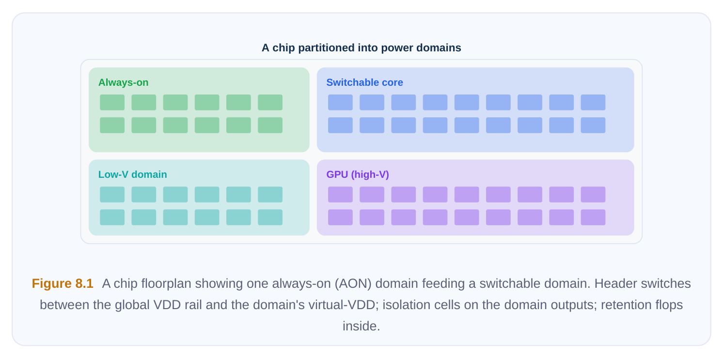
- Power switches (header/footer): Large transistors, usually distributed as a daisy-chained network of switch cells, that connect the real supply to the domain's virtual rail. A header switch sits between VDD and virtual-VDD; a footer sits between VSS and virtual-VSS. The enable signal that turns them on comes from the always-on logic.
- Isolation cells: Clamp the outputs of a powered-down domain to a known, legal value (0 or 1) so that downstream always-on logic never sees a floating, mid-rail input. They live on the receiving side's supply or on an always-on supply.
- Retention cells: Special flops with a shadow latch on an always-on supply. They hold state across the shutdown so the block can resume mid-computation instead of cold-booting.
- Level shifters / enable-level-shifter combos: Where the switchable domain runs at a different voltage, signals crossing the boundary need level translation; the isolation function is often merged into the same cell. Everything below is about wiring these correctly and proving you did.
Shutdown Data Preparation
Before a tool can power-gate a domain, you must hand it a complete, consistent description of intent — almost always captured in an IEEE 1801 (UPF) or CPF power-intent file. "Data preparation" is the act of making that intent real in the netlist and physical database. Five things must all be in place.
- 1. The switch network. Switch cells must be instantiated, placed across the domain, and stitched into
an enable chain. The chain matters: enabling thousands of switches simultaneously dumps a huge inrush current. A staged ("acknowledge-driven" or buffered) chain turns them on in waves so the virtual rail charges gracefully.
- 2. Always-on (AON) control routing. Every signal that must survive the shutdown — switch enables,
isolation enables, retention save/restore, the wake handshake — has to be routed on a supply that is never gated. A single switch-enable accidentally routed through the gated domain creates a chickenand-egg deadlock: the domain can never turn itself back on.
- 3. Isolation on outputs. Every net that leaves the switchable domain and drives a powered
destination must pass through an isolation cell with a defined clamp value. Inputs into the domain generally do not need isolation, but they may need to be held by the driver.
- 4. Retention for needed state. Decide what state must persist. Retaining everything is expensive
(each retention flop is larger and adds an AON pin); retaining nothing forces a cold boot on every wake. The architect picks the minimal set — typically configuration and a small amount of resumable context.
- 5. The power-state / mode table. This is the contract that says which domains are off in which mode.
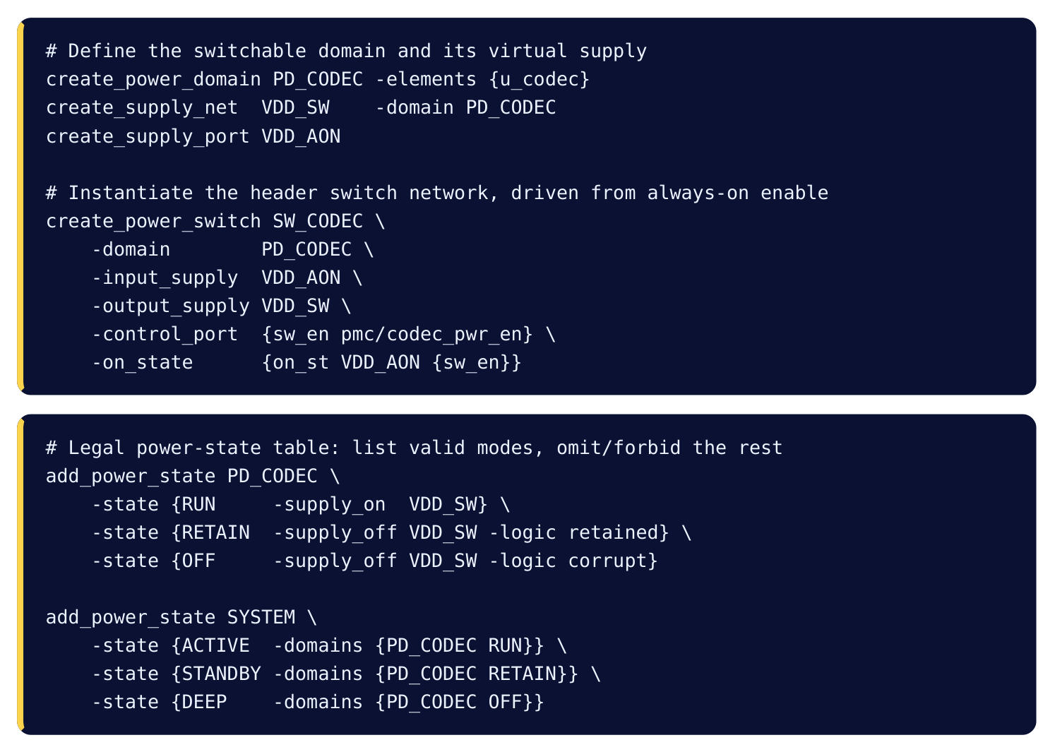
It enumerates every legal combination of domain states (ON, OFF, retained, scaled voltage) and, critically, declares illegal combinations so verification can flag them. The table is also where you encode dependencies: if domain B's outputs are isolated against domain A's supply, then any mode that turns A off while B drives into A is illegal and must be marked as such. These cross-domain constraints are exactly the bugs that slip past block-level checks and surface only in full-chip poweraware simulation. A subtle preparation detail that trips people up is the always-on island inside an otherwise switchable region. Retention shadow latches, the level-shifter/isolation enable logic, and any small logic that must keep running all need a live rail physically routed into the middle of a domain whose main rail is being cut. Physically this means a secondary always-on power mesh, special always-on buffers/inverters that have their own dedicated supply pin, and placement rules that keep those cells reachable. If the floorplan does not reserve room for the always-on mesh early, you discover the problem during routing when it is expensive to fix. Here is a generic sketch of expressing that intent. Names are illustrative, not tied to any tool.
PREREQUISITES CHECKLIST
Before you green-light a shutdown implementation, walk this table. A "no" anywhere is a stop-the-line item.
| Prerequisite | Why it matters | Failure if skipped |
|---|---|---|
| Switch network placed and | Provides the path to cut/restore stitched | No way to gate the domain at all supply |
| Staged switch-enable chain | Limits inrush as virtual rail charges | Brown-out of neighbors on wake |
| AON routing for all control nets | Control must survive the off-state | Deadlock; domain cannot re- |
enable
| Isolation on every domain output | Prevents floating mid-rail into live | Crowbar current, functional |
|---|---|---|
| logic | corruption | |
| Retention set chosen and | Preserves needed state across off | Lost config / forced cold boot |
connected
| Power-state table complete | Defines legal vs illegal modes | Unverifiable intent; missed bugs |
|---|---|---|
| Sequencer (controller) | Drives gate/iso/save/restore in implemented | Wrong ordering corrupts state order |
Power / Domain Coverage Analysis
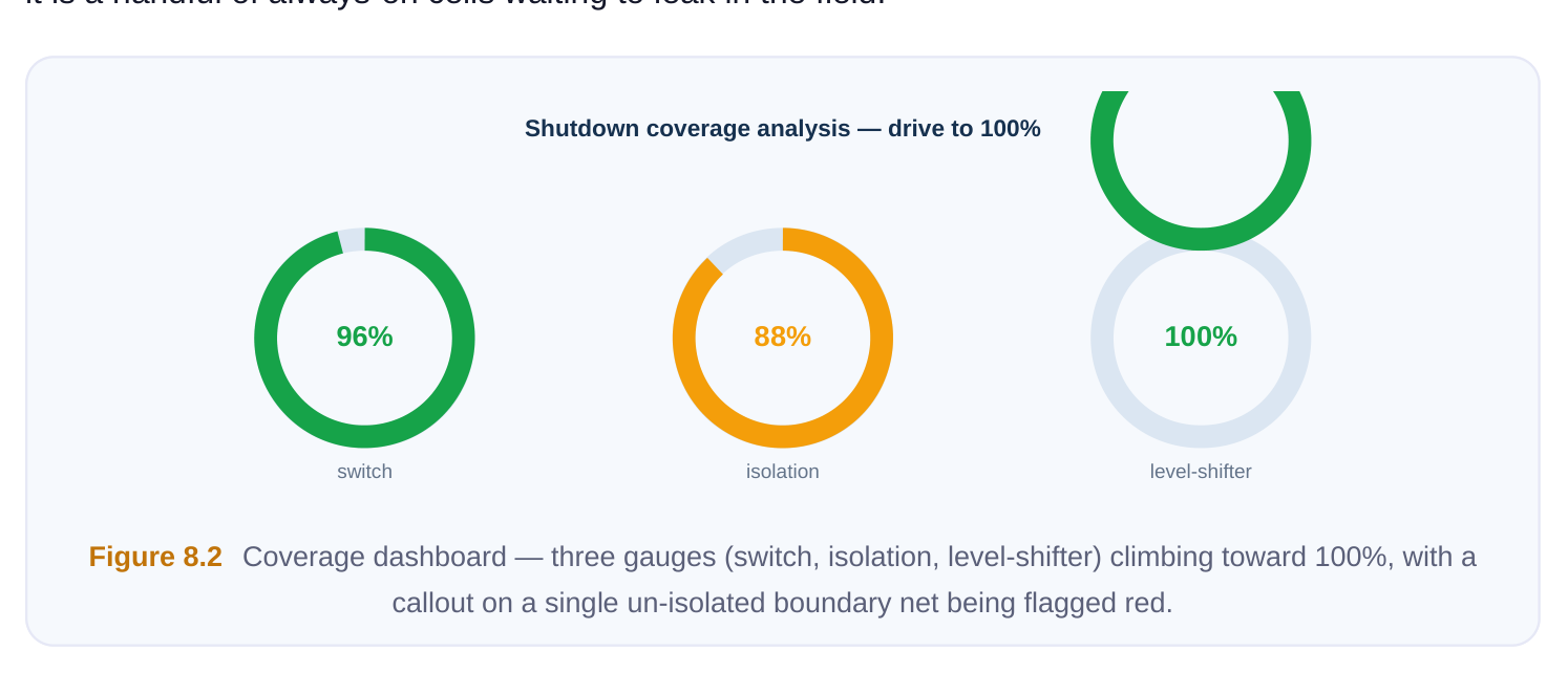
This is the verification step interviewers love, because it is the one that silently lets bugs through. The question coverage answers is blunt: did every cell that is supposed to be switched actually get connected to the virtual rail, and did every output that needs isolation actually get an isolation cell? The danger is subtle. Suppose the domain has 200,000 standard cells but, due to a hierarchy mismatch or a missing -elements entry, 1,500 of them stayed bound to the always-on rail. Functionally the design simulates fine — those 1,500 cells are more powered than intended. But when you power-gate the domain in silicon, those cells stay live, leaking exactly the power you were trying to remove, and possibly driving stale values into supposedly-off logic. Coverage analysis catches this on the desktop. Coverage is reported as a percentage and you drive it to 100%:
- Switch coverage = cells correctly on virtual rail ÷ cells that should be on virtual rail.
- Isolation coverage = boundary outputs correctly isolated ÷ boundary outputs requiring isolation.
- Level-shifter coverage = voltage-crossing nets correctly shifted ÷ nets requiring a shifter. A generic invocation looks like this:
# Check that domain intent is fully realized in the netlistanalyze_power_domain -domain PD_CODEC -report rail_bindinganalyze_isolation -domain PD_CODEC -check missing -check redundantanalyze_level_shifter -domain PD_CODEC -check missingreport_power_coverage -domain PD_CODEC -format summaryTwo failure modes appear: missing protection (a cell on the wrong rail, an un-isolated output — these are correctness bugs) and redundant protection (an isolation cell on a net that never needs it, or a level shifter where both sides share a voltage — these are area/power waste). Good flows report both. It pays to understand why coverage gaps appear, because the same root causes recur across projects. The leading cause is a mismatch between the logical hierarchy named in the power intent and the physical hierarchy after synthesis flattened or replicated some instances — a cell that the intent expected to find underu_codecended up promoted to a parent scope and silently inherited the always-on rail. The second is engineering change orders late in the flow: a net added in an ECO crosses a domain boundary but no one re-ran the isolation strategy, so the new net is un-isolated. The third is glue logic that the architect did not anticipate, such as a tie-cell or buffer auto-inserted across a boundary. Because all three produce a design that simulates correctly, coverage analysis — not simulation — is your detector. Run it after every major netlist change, not just once before tapeout.
COVERAGE OUTCOMES AND FIXES
| Coverage finding | Root cause | Fix |
|---|---|---|
| Cell left on AON rail | Missing from domain -elements ; hierarchy mismatch | Re-bind cell to domain; correct element list |
| Output not isolated | Boundary not declared; net added late in ECO | Add isolation strategy on that boundary net |
| Redundant isolation | Net stays within one always-on path cell | Remove cell; reclaim area and leakage |
| Switch not in enable | Stitching script missed an instance chain | Re-stitch; verify chain continuity end to end |
| Level shifter missing | Voltage pair not in the crossing rules | Add shifter; update level-shifter |
strategy
| Retention pin on gated | Save/restore mis-connected | Move retention control to AON |
|---|---|---|
| rail | supply |
Drive every coverage metric to 100% before tapeout. A 99.9% switch coverage is not "almost done" — it is a handful of always-on cells waiting to leak in the field.
Shutdown Sequencing Recap
Order is everything. The hardware power-management controller — itself always-on — must drive the protective machinery in a strict sequence. Powering down:
- 1. Gate the clock to the domain so nothing toggles during the transition.
- 2. Assert isolation so outputs clamp to safe values before the supply drops.
- 3. Save state by asserting the retention save signal, copying live flops into their shadow latches.
- 4. Switch off by de-asserting the switch enable, collapsing the virtual rail.
Waking up reverses the order, and the reversal is not optional:
- 1. Switch on — assert the switch enable (staged) and wait for the virtual rail to settle.
- 2. Restore state — pulse the retention restore so flops reload from their shadow latches.
- 3. De-assert isolation — only now are the outputs valid and safe to release.
- 4. Un-gate the clock — resume operation.
The single most common sequencing bug: releasing isolation before the rail has fully recovered, so partially-powered gates drive garbage into the rest of the chip. The second most common: restoring before the supply is stable, so the retention reload latches onto an unsettled rail.
VERIFYING THE SEQUENCE
You verify ordering at two levels. Statically, a power-aware structural/sequence checker confirms that, for every legal mode transition in the power-state table, the controller's outputs obey the gate→iso→save→off ordering (and its reverse). Dynamically, power-aware simulation runs the actual transitions with the supplies modeled, so an out-of-order restore shows up as an X-propagation on the domain outputs. Treat any X that escapes a powered-down domain into live logic as a hard failure, not a warning.
# Sequence and connectivity checks against the power-state table
check_power_sequence -domain PD_CODEC \
-order {clock_gate isolation retention_save power_off}
check_isolation_control  -domain PD_CODEC -aon_required
check_retention_control  -domain PD_CODEC -aon_required
report_mode_transitions  -from ACTIVE -to DEEP -check legal
Wake-Up Considerations
Turning a domain on is harder than turning it off, because now physics and timing both push back. Inrush current. An empty virtual rail is a discharged capacitor. Slam every switch on at once and you draw a current spike that can sag the global rail and brown out neighboring domains — including, in the worst case, the controller trying to manage the wake. This is precisely why the switch network is a staged chain: early switches charge the rail partway, later switches finish it, spreading the inrush over time. Some designs add weak "trickle" switches that pre-charge before the main switches fire. Restore time / wake latency. From the moment software requests wake to the moment the block is usable, you pay: switch-chain propagation + rail-settle time + retention restore + isolation release + clock-tree settling. For a deep-sleep domain this can be hundreds of nanoseconds to microseconds. If a use case needs faster wake than the domain can deliver, the architecture is wrong — either keep the domain in retention (much faster) or split it so only a small always-on portion stays live. Retention versus cold boot. This is a fundamental architectural trade and a classic interview discussion:
| Strategy | Leakage when off | Wake latency | Area / pin cost | Use when |
|---|---|---|---|---|
| Full power-off | Lowest (≈ zero) | Highest (re-init (cold boot) | Lowest from scratch) | Long idle, state is cheap to rebuild |
| State retention | Low (only shadow latches + AON live) | Low (just restore) | Higher (retention flops, AON net) | Frequent sleep/wake, resumable context |
| Stay in clock- | High (full rail live) | Lowest | None extra gated active | Idle windows too short to gate |
The right answer depends on the duty cycle. If a block sleeps for milliseconds and wakes constantly, retention's fast wake justifies its leakage and area. If it sleeps for seconds at a time, cold boot's nearzero leakage wins despite the longer wake.
Interview Q&A
still leaks heavily when it should be off. What do you check first? Switch coverage. The classic cause is cells that were never bound to the virtual rail — a hierarchy or -elements mismatch leaves them on the always-on rail. They simulate fine (they are simply always powered) but never actually shut off in silicon. Re-run domain/rail-binding coverage and drive switch coverage to a true 100%; do not accept 99.x%.
get wake wrong? Sleep protects before removing power: isolate and save, then cut the rail, so nothing floats and no state is lost. Wake must restore power and confidence before releasing protection: switch on, let the rail settle, restore state, then release isolation, then un-gate the clock. If you release isolation before the rail is settled, partially-powered gates drive invalid logic into live downstream domains — functional corruption that often shows up as intermittent silicon failures.
large transient drawn when the discharged virtual rail charges up at wake. If all switches enable simultaneously it can sag the global supply and brown out neighbors. The mitigation is a staged switch-enable chain (often with weak pre-charge switches first, then strong switches) so the rail charges in controlled steps, capping peak current. The trade-off is longer wake latency, which you budget against the use case.
and wake-latency requirements. Retention adds area (larger flops) and an always-on net, and leaves a small residual leakage, but gives fast wake — ideal for frequent, short sleeps with resumable state. Full power-off gives near-zero leakage and lowest area but forces a cold re-initialization, so it suits long idle periods where rebuilding state is acceptable. Quantify it: retained leakage × idle time + restore energy versus cold-boot re-init energy, weighted by how often the block sleeps.
Key Takeaways
- Shutdown is the only technique that drives a block's leakage to essentially zero; it is the biggest single leakage lever and the most failure-prone.
- Data preparation means five things are all in place: the switch network, always-on control routing, output isolation, the chosen retention set, and a complete power-state/mode table — best captured in IEEE 1801 (UPF) or CPF.
- Coverage analysis verifies that every cell that should be switched is on the virtual rail and every output that needs isolation has it; report it as a percentage and drive it to a genuine 100%.
- Distinguish missing protection (correctness bugs) from redundant protection (waste); both deserve cleanup.
- Sequence is law: gate → isolate → save → switch off; reverse on wake, with a rail-settle wait before restore and isolation release. Verify statically and with power-aware simulation, and treat any X escaping a gated domain as a hard fail.
- Wake costs inrush current and latency; stage the switch chain to cap inrush, and choose retention versus cold boot from the duty cycle and wake-latency budget.
Comments
Leave a Reply