 ChipBuddy
← Home
ChipBuddy
← Home
Leakage Power Optimization Techniques
Why Leakage Became the Static-Power Villain
For most of the history of CMOS, designers worried almost exclusively about dynamic power — the energy burned charging and discharging capacitance every time a node toggles. Static power, the power a circuit consumes simply by being powered on, was a rounding error. That is no longer true. As process nodes shrank from 90 nm down through 28 nm, 16/14 nm FinFET, and beyond, the supply voltage scaled down to keep dynamic power and electric fields in check. To preserve switching speed at lower supply voltage, foundries had to scale the transistor threshold voltage (Vt) down as well. The problem is that subthreshold leakage current rises exponentially as Vt drops. A modest reduction in threshold to win back a few picoseconds of delay can multiply the leakage of that transistor severalfold. Layer on top of this the sheer transistor count of modern SoCs — billions of devices, the vast majority idle at any given instant — and leakage becomes a first-class design constraint. In a battery-powered part that spends most of its life in standby, leakage can dominate the total energy budget outright. Even in always-active datacenter silicon, leakage scales with temperature, so a hot die leaks dramatically more than a cool one, creating a thermal-runaway feedback loop that must be designed against.
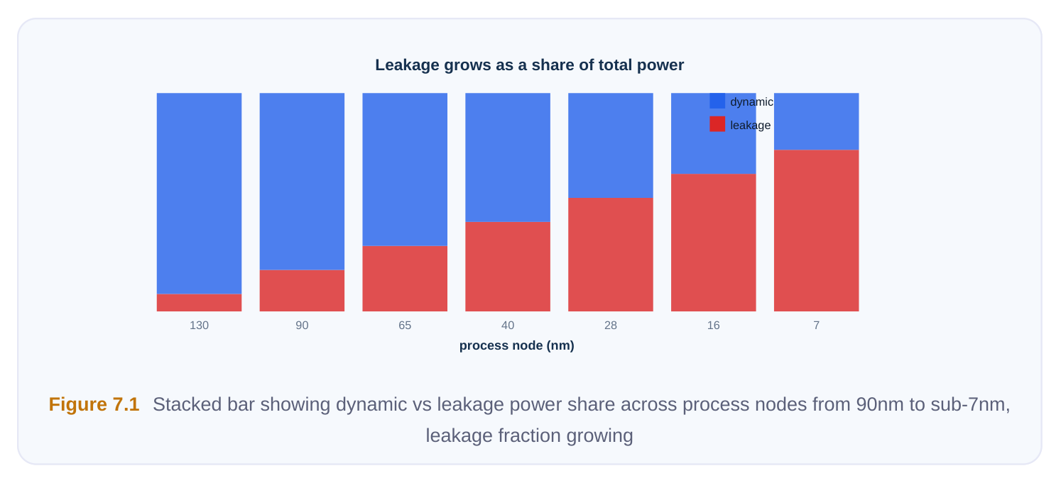
Leakage has several physical components — subthreshold conduction, gate-oxide tunneling, and junction leakage among them — but from the implementation engineer's chair, the dominant lever is the choice of threshold voltage per cell. The implementation tool cannot redesign the transistor, but it can choose, gate by gate, which flavor of a logically identical cell to instantiate. That single degree of freedom is the foundation of nearly every leakage-recovery technique discussed in this chapter.
The Multi-Vt Library: The Core Knob
Standard-cell libraries at low-power nodes ship in multiple threshold-voltage flavors of the same logical cells. A two-input NAND exists as an HVT (high-Vt), an SVT/RVT (standard or regular Vt), and an LVT (low-Vt) variant — sometimes more, including ultra-low-Vt and ultra-high-Vt tiers. All three are pincompatible and, critically, share the same physical footprint: identical cell width, height, and pin locations. They differ only in the transistor implant that sets the threshold. The relationship is a clean trade: higher Vt means lower leakage but slower switching; lower Vt means faster switching but much higher leakage.
| Vt Flavor | Threshold | Leakage (relative) | Speed (relative) | Typical Use |
|---|---|---|---|---|
| HVT (high-Vt) | Highest | ~1x (baseline, | Slowest lowest) | Non-critical paths, idle-heavy logic |
| SVT / RVT | Medium | ~5x–10x | Medium | Default fill, balanced paths |
| LVT (low-Vt) | Low | ~20x–50x | Fastest | Critical-path gates only |
| ULVT (ultra- | Lowest | ~50x–100x+ | Fastest low) | Last-resort timing fixes available |
The exact ratios vary by foundry and node, but the order-of-magnitude leakage penalty for each step down in Vt is the constant that drives strategy. Because the leakage cost of LVT is so steep, the golden rule is simple: use the highest Vt you can get away with on every path, and spend the LVT
budget only where timing absolutely demands it. A well-optimized block often ends up 70–90% HVT/SVT by cell count, with LVT confined to a thin sliver of speed-critical logic.
The Leakage-vs-Timing Optimization Loop
Leakage recovery is fundamentally a timing-aware operation, and it is best understood as a loop that runs late in the implementation flow — typically after clock tree synthesis and routing, once timing is reasonably accurate, and again during signoff-driven ECO. The loop has two complementary halves. First, the tool may down-convert cells to higher Vt. Any gate sitting on a path with positive slack is a candidate to be swapped from LVT to SVT, or SVT to HVT. The swap slows the gate slightly, eating into that path's slack, but recovers leakage. As long as the path stays non-negative after the swap, the trade is free in timing terms and pure profit in power. Second, where the tool has earlier (during timing closure) up-converted cells to LVT to fix violations, the leakage pass tries to claw those back. If slack has improved since — because of routing changes, useful-skew adjustments, or other optimizations — an LVT gate that is no longer needed for speed gets reverted to a lower-leakage flavor. The engine ranks candidates by a figure of merit that weighs leakage gain against slack cost. A gate that sits on a path with large positive slack and contributes significant leakage is the most attractive swap. A gate on a near-critical path, even if it leaks a lot, is risky and gets deferred. The tool processes candidates greedily, re-timing incrementally after each batch so it never pushes a path negative.
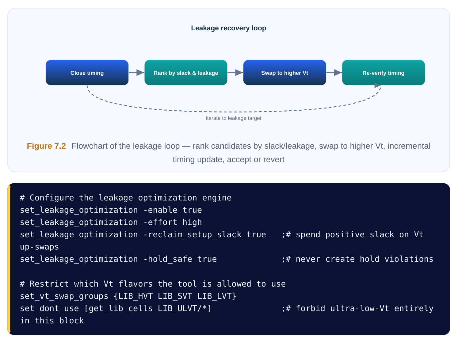
Note the explicit constraints. Teams routinely forbid the highest-leakage tiers on power-sensitive
blocks, or cap the percentage of LVT cells the tool may leave behind. These guardrails keep the optimizer from trading away too much power for marginal timing it did not actually need.
Footprint-Compatible Swaps: Why They Are Free
The reason multi-Vt swapping is so powerful in physical implementation is that it is placement- and routing-neutral. Because the HVT, SVT, and LVT variants of a cell occupy the identical footprint with identical pin geometry, the tool can substitute one for another in place without moving the cell, ripping up its connections, or perturbing neighbors. No legalization, no incremental routing, no risk of opening new DRC violations. This is what makes Vt swapping the workhorse of late-stage and ECO leakage recovery. A signoff ECO can swap thousands of cells to higher Vt and the layout database barely changes — the same metal, the same placement, just a different implant mask. Contrast this with techniques like cell resizing, which may change cell width and therefore require legalization and rerouting. Vt swaps are the cleanest, lowest-risk leakage lever available, which is why they are applied last, after the physical picture is stable.
# Footprint-preserving in-place Vt swap of a single cell
swap_cell [get_cells u_alu/add_42] -lib_cell LIB_HVT/NAND2_X1
# Bulk swap: convert all positive-slack LVT cells in a region to SVT
foreach c [get_cells -filter "lib_cell_threshold==LVT && slack > 0.10"] {
swap_cell $c -to_threshold SVT -footprint_compatible true
}
The Other Leakage Levers
Multi-Vt swapping is the primary technique, but a complete leakage strategy uses several others, each with its own mechanism and cost. The implementation engineer should know all of them and when each applies. Selective downsizing. A larger drive-strength cell leaks more than a smaller one because it has more (and wider) transistors. On paths with comfortable slack, swapping an X4 buffer for an X2, or an X2 for an X1, recovers both leakage and dynamic power, and shrinks area. The risk is that a smaller cell drives its load more slowly, so downsizing must be slack-aware exactly like Vt swapping. Unlike Vt swaps, downsizing usually changes the footprint, so it is done earlier when legalization is still cheap, or carefully during ECO with reserved placement room. Minimizing redundant logic. The lowest-leakage gate is the one that does not exist. Logic restructuring, constant propagation, redundancy removal, and de-cloning of over-replicated buffers all reduce transistor count, and every removed transistor removes its leakage. This is largely a synthesisera and early-implementation activity, but cleanup ECOs can still prune dangling and unused logic that survived into the physical netlist.
Power gating / shutdown. The most aggressive static-power technique is to cut the supply to entire blocks when idle, driving their leakage essentially to zero. This is implemented with sleep transistors, isolation cells, retention registers, and a power-intent description in CPF or UPF (IEEE 1801). Power gating attacks leakage at its root — no voltage, no leakage current — but it carries significant complexity: wake-up latency, rush-current management, state retention, and verification overhead. It is covered in depth in a later chapter; here it is enough to place it as the heaviest hammer in the leakage toolkit, reserved for blocks with meaningful idle windows. Body bias. Applying a reverse body bias raises the effective threshold of transistors and cuts leakage in standby; forward body bias lowers it to recover speed when active. This is an adaptive, voltagedomain-level technique requiring bias network routing and well taps, and is briefly noted here and cross-referenced to the chapter on voltage and bias control. It complements rather than replaces Vt swapping. Clock gating — a dynamic-power contrast. Clock gating disables the clock to registers and downstream logic that do not need to update, killing the switching activity in idle regions. It is enormously effective — but it targets dynamic power, not leakage. A clock-gated register still leaks; it just stops toggling. This distinction trips up candidates constantly: gating the clock saves dynamic energy, while raising Vt or removing the supply saves leakage. A robust low-power design uses both, because they attack different halves of the total power equation.
| Technique | Primary Saving | Footprint Impact | Risk Level | Effort / Stage |
|---|---|---|---|---|
| Multi-Vt swap (up- | Leakage | None (in-place) | Low convert) | Low — late / ECO |
| Selective downsizing | Leakage + dynamic + | Changes width | Medium area | Medium — mid- flow |
| Redundant-logic | Leakage + area | Removes cells | Low– removal | Synthesis / early Medium |
| Power gating | Leakage (near-total) | Major (sleep FETs, | High isolation) | High — architectural |
| Body bias | Leakage (standby) | Bias network, taps | Medium– | High — full-chip |
High
Clock gating Dynamic only Adds ICG cells Low Synthesis / RTL You cannot optimize what you do not measure. Two reports anchor the leakage workflow: a power breakdown that isolates the leakage component, and a Vt-mix summary that tells you how the optimizer spent the threshold budget.
# Report total power with the leakage component broken out
report_power -leakage -hierarchy -levels 2
# Report static power only, sorted to find the worst offenders
report_power -leakage -sort_by leakage -nworst 50
# Summarize the Vt distribution across the design
report_threshold_voltage_group -summary
A typical leakage report separates internal (short-circuit), switching, and leakage components, and lets you drill down by hierarchy to find which blocks dominate. The Vt-mix report is the one to watch over the course of a project — it expresses the percentage of cells (and the percentage of leakage) attributable to each flavor.
| Vt Group | Cell Count | % of Cells | Leakage (uW) | % of Leakage |
|---|---|---|---|---|
| HVT | 184,200 | 61% | 12.4 | 9% |
| SVT | 96,500 | 32% | 41.7 | 31% |
| LVT | 21,300 | 7% | 80.9 | 60% |
| Total | 302,000 | 100% | 135.0 | 100% |
This table tells a story the cell counts alone hide: LVT is only 7% of the cells but 60% of the leakage. That is the signature of a healthy-but-improvable design — the obvious next move is to hunt for LVT cells on positive-slack paths and reclaim them to SVT or HVT. Tracking this mix release over release also catches regressions: if a timing-closure pass quietly inflated the LVT count to hit a frequency target, the leakage report will show it before tape-out, when there is still time to run a recovery ECO.
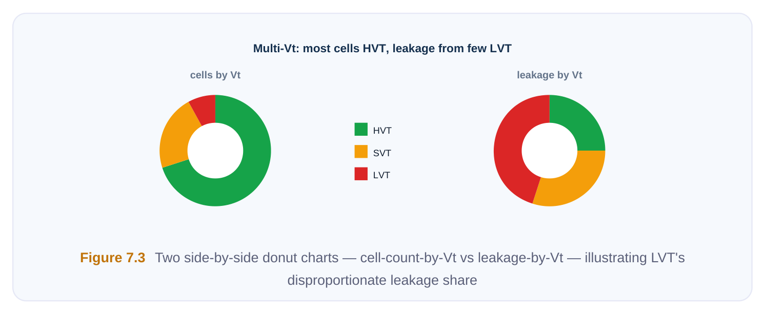
A practical signoff cadence is: close timing, run leakage recovery to push everything possible to higher Vt, re-verify timing including hold, regenerate the Vt-mix and leakage reports, and confirm the LVT fraction is within the agreed budget. Iterate until the design hits its leakage target without reopening timing violations.
Interview Q&A
advanced nodes? Dynamic power scales roughly with capacitance, voltage squared, and activity, all of which trend favorably as you shrink. Leakage, specifically subthreshold leakage, depends exponentially on threshold voltage. To keep transistors fast at lower supply voltages, foundries lowered Vt, and that exponential relationship means even a small Vt reduction causes a large leakage increase. Combine that with billions of mostly-idle transistors and strong temperature dependence, and leakage becomes the dominant static-power term — sometimes the dominant power term overall in standby-heavy designs.
cells whose paths have positive setup slack — those have timing margin to spare. It ranks candidates by a figure of merit combining how much leakage the swap saves against how much slack it consumes. High-leakage cells on high-slack paths are swapped first. It applies swaps incrementally, re-timing after each batch and being careful not to push any path negative on setup or create hold violations. Cells on near-critical paths are left alone. The result is the maximum leakage reduction achievable without disturbing timing closure.
different from resizing? The different Vt flavors of a cell share an identical footprint and pin geometry — only the transistor implant differs. So the tool can substitute one in place without moving the cell or touching its routing, meaning no legalization and no new DRC or routing work. That makes Vt swapping the safest, lowest-disruption leakage lever, ideal for late-stage and signoff ECOs. Resizing, by contrast, usually changes the cell's width, which forces legalization and incremental routing and can open new violations — so it is riskier and done earlier.
that is a category error worth correcting gently. Clock gating stops idle registers and downstream logic from toggling, which saves dynamic power. A gated register still has its supply connected, so it still leaks; you have not touched the leakage component at all. To cut leakage you raise Vt, downsize, remove redundant logic, apply body bias, or power-gate the block to remove the supply entirely. Clock gating and leakage recovery are complementary — they attack different halves of total power — but they are not interchangeable.
Key Takeaways
- Leakage dominates static power at advanced nodes because subthreshold current rises exponentially as threshold voltage scales down, multiplied across billions of mostly-idle transistors and amplified by temperature.
- Multi-Vt cell swapping is the primary implementation lever: use the highest Vt the timing allows everywhere, and reserve low-Vt for the thin slice of truly critical paths.
- The leakage loop is timing-aware — it ranks candidates by leakage gain versus slack cost, up- converts positive-slack cells to higher Vt, and reclaims unneeded LVT, re-timing incrementally so it never breaks setup or hold.
- Vt swaps are footprint-compatible and therefore placement/routing-neutral, making them the safest late-stage and ECO leakage technique; resizing and logic removal change geometry and must run earlier.
- Round out the strategy with selective downsizing, redundant-logic removal, body bias, and power gating for idle blocks — and remember clock gating saves dynamic power, not leakage.
- Always close the loop with
report_power -leakageand a Vt-mix report; the cell-count-versus- leakage-share comparison reveals where the next recovery opportunity hides.
Comments
Leave a Reply