 ChipBuddy
← Home
ChipBuddy
← Home
How the Flow Changes for Low Power
Chapter 3 — How the Flow Changes for Low Power (Special
Handling)
A conventional physical-implementation flow is built on a comfortable lie: that there is exactly one supply voltage, that it is always present, and that every cell in the design can be trusted to behave the moment power is applied. Synthesis, floorplan, placement, clock tree, routing, and timing closure all quietly assume this single, eternal rail. The moment you introduce multiple voltages, supplies that can be switched off, or supplies that scale up and down at runtime, that assumption shatters — and it shatters at every stage, not just one. The job of a low-power-aware flow is to repair each broken assumption with explicit, checkable handling. This chapter walks the flow end to end and explains the low-power twist that gets bolted onto each step. The unifying idea is simple: a separate description of power intent — captured in a format such as IEEE 1801 (UPF) or CPF — rides alongside the netlist from the very first command to the very last, and every stage must read it, honor it, and be re-checked against it.
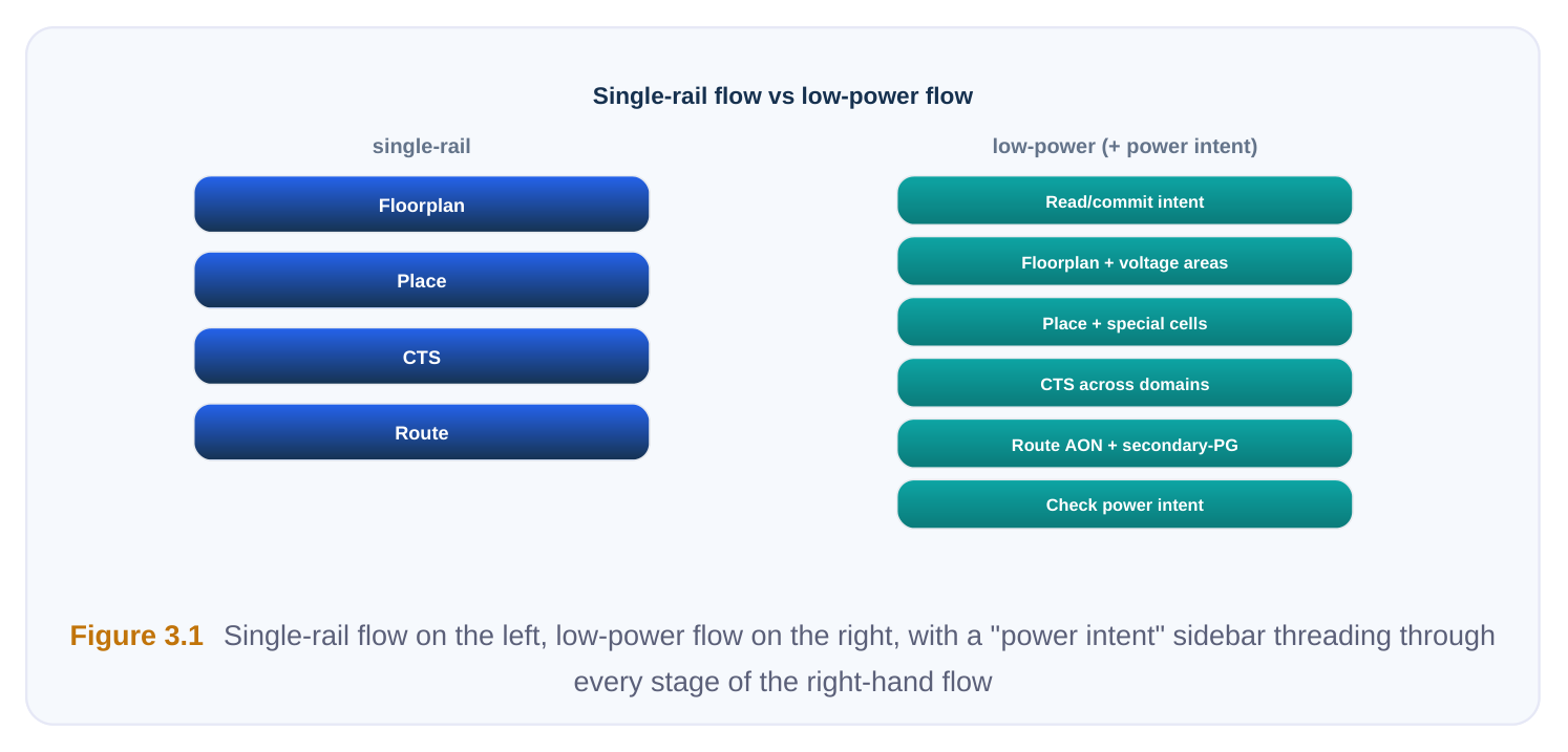
Read and Commit Power Intent Up Front
In a single-supply flow you load a netlist and libraries and start working. In a low-power flow you must additionally load the power-intent description before you do anything structural, because that file is what tells the tool which nets are which supply, where the power domains are, and what special cells are legally required at their boundaries. The intent file does several jobs at once. It declares supply nets and supply ports, defines power domains (groups of logic that share a supply and switching behavior), specifies power switches for domains that can be shut off, and states the rules for isolation, level shifting, and retention. Reading it is not enough — the tool must commit it, which means elaborating the abstract intent against the real netlist hierarchy so that every domain boundary maps to actual pins and instances.
# Stage 0: bring power intent in and bind it to the design
read_power_intent  -file design_power_intent.upf
commit_power_intent
# from here on, every instance knows its domain and supply
report_power_domains
report_supply_nets
If you skip the commit, downstream stages happily place and route as if everything were one rail, and the violations only surface much later — usually at sign-off, which is the most expensive place to find them.
Floorplan: Voltage Areas and the Switch Plan
In a normal floorplan you place macros, define the core area, and reserve channels. The low-power addition is the voltage area (also called a power region): a physical chunk of the die reserved for a particular power domain. Logic belonging to a switched-off domain must live inside its voltage area so
that the switched supply can be delivered there and nowhere else. Mixing domains freely across the floorplan would make it impossible to route the rails cleanly or to contain a powered-down region. Alongside voltage areas you commit to a power-switch plan: how each switchable domain will be turned on and off. Two common physical styles exist, and the choice ripples through the rest of the flow.
| Switch style | How it is built | Trade-off |
|---|---|---|
| Ring (header/footer | Switch cells form a ring around the | Lower IR drop into the region, but consumes |
| ring) | voltage area | perimeter area |
| Grid / column | Switch cells distributed in columns across the region | Better current uniformity, more flexible, more cells to control |
You also decide switch granularity (coarse-grain blocks vs. fine-grain in-cell switches) and the enable daisy-chain ordering, because switching a large region on all at once causes a current surge ("rush current" or inrush) that can collapse the always-on rail. The floorplan is where you reserve room for this.
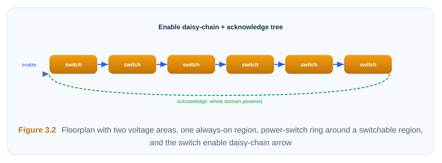
Power Planning: Multiple Rails, Always-On, and Switched
A single-supply design needs one power mesh. A low-power design needs several, and they must coexist:
- The always-on rail, which never switches off and feeds cells that must survive a power-down (isolation control logic, retention storage, level-shifter supplies).
- One or more switched rails, delivered to switchable domains through the power switches.
- Possibly multiple voltage rails at different levels for voltage-scaled or multi-voltage domains. The hard part is that the always-on rail often has to thread through a switchable region to reach always-on cells that physically sit inside it (for example, the isolation cells guarding that region's outputs). So your power plan carries a primary mesh, a secondary always-on mesh, and the switched mesh fed from the switch outputs, all overlapping without shorting.
# Build the always-on mesh first, then the switched mesh
create_power_mesh -net VDD_AON      -layers {M7 M8} -always_on true
create_power_mesh -net VDD_SW_VIRT  -layers {M5 M6} -source switch_out
connect_supply    -net VDD_AON      -pin VDD     -on_cells {iso_* ret_*}
connect_supply    -net VDD_SW_VIRT  -pin VDD     -domain CPU_DOMAIN
A useful mental model: the switch sits between the "true" (real) supply and the "virtual" supply that the domain's ordinary cells see. Always-on cells tap the true supply directly; switchable cells tap the virtual supply downstream of the switch.
Placement: Domain Membership and Special-Cell Rules
Ordinary placement optimizes for timing and congestion. Low-power placement adds a hard constraint: every cell must be placed inside the voltage area of the domain it belongs to. A flip-flop assigned to the CPU domain cannot drift into the always-on region just because there is whitespace there, because the rail under that whitespace is the wrong supply. Several special cells also have placement rules of their own:
- Power-switch cells must align to their ring or columns and connect to the enable chain in order.
- Always-on cells (isolation, retention control) must sit where the always-on rail actually reaches.
- Level shifters and isolation cells prefer placement near the domain boundary they guard to keep the protected net short.
# Confine placement to legal regions per domainset_placement_region -domain CPU_DOMAIN -area $cpu_voltage_areaset_placement_region -domain AON_DOMAIN -area $aon_voltage_areaplace_design -honor_power_domains truecheck_cell_domain_membership
Inserting the Special Low-Power Cells
This stage has no equivalent in a single-supply flow because the cells themselves only exist to manage multiple or switchable supplies. There are three families, and each fixes a different broken assumption:
| Cell type | Problem it solves | Typical placement |
|---|---|---|
| Isolation cell | A powered-down domain's output floats and feeds garbage into a live domain | Output boundary of the switchable domain, on always-on supply |
| Level shifter | A signal crosses from one voltage level to another and would otherwise be misread | At the crossing, may need both supplies |
| Retention cell / | State must survive a power-down so the block | Inside the switchable domain, with an |
| register | can resume quickly | always-on retention supply |
The intent file declares where these are required (which domain boundaries, which signals, what clamp value an isolation cell should hold). The implementation tool inserts and connects them, including their control signals — isolation enable, retention save/restore — which must be driven from always-on logic. A classic bug is inserting a perfectly good isolation cell but routing its enable on the switched rail, so the guard itself dies the instant it is needed.
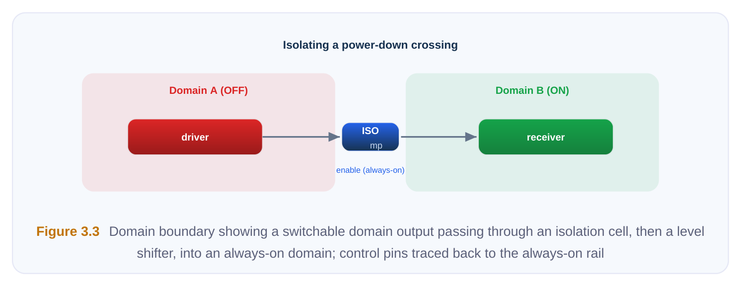
Clock Tree: Staying Alive and Crossing Domains Correctly
A normal clock tree is built for one supply and balanced for skew. Low power complicates this in two directions. First, parts of the clock network may need to stay alive while the logic they feed is asleep — for example, a clock that must keep running to wake the block up, or a retention clock. Those clock buffers belong on the always-on rail even though they sit inside a switchable region. Second, when a clock crosses a voltage boundary, the clock buffers on each side run at different voltages, so the tree must include level shifting in the clock path and the skew budget must account for the different cell delays on each side of the shift.
# Keep wake-up clock buffers always-on; level-shift across the boundary
set_clock_tree_options -through CPU_DOMAIN -buffer_supply VDD_AON
insert_level_shifter   -on_path  clk_cpu_xdomain
balance_clock_tree     -across_power_domains true
Clock gating, the workhorse of dynamic-power reduction, also lives here. Integrated clock-gating cells are inserted (often during synthesis but verified physically) and must themselves be powered correctly and balanced into the tree.
Routing: Secondary PG and Always-On Nets
Standard routing connects signal nets and the single PG mesh. Low-power routing adds secondary power/ground connections: cells such as level shifters and always-on cells have a second supply pin that must reach a different rail than their neighbors. Routing has to pull the always-on rail to those specific pins through what is otherwise switched territory, without shorting the two supplies.
The other special case is the set of always-on signal nets — isolation enables, retention controls, the switch enable daisy-chain — which must be routed so they remain driven when their region is off. These are functionally ordinary nets, but their source and buffering must stay on the live rail end to end.
# Hook up the second supply pin on dual-rail cells, then route
route_special -nets {VDD_AON VSS} -secondary_pg true
route_signal  -keep_always_on {iso_en* ret_save* switch_en*}
verify_pg_connectivity -check_secondary true
Power-Aware Optimization Across Domains
Optimization (sizing, buffering, restructuring) normally chases one timing graph. With multiple supplies, the tool must optimize across domains while respecting that a buffer inserted on a cross-domain net might need to be a level shifter, that a cell in a low-voltage domain is inherently slower, and that an always-on net cannot be buffered with a switchable-rail buffer. Multi-voltage timing also means a path can be fast in one mode and slow in another, so optimization is driven by the power-state definitions discussed next.
Power-State Tables and Mode-Driven Analysis
The single biggest analysis change is that "the design" is no longer one thing. A multi-domain chip has many legal combinations of domain states — on, off, or scaled to a particular voltage — and each combination is a distinct operating mode that must close timing and pass IR/EM checks on its own. These combinations are captured in a power-state table (a mode definition matrix). It is the contract that tells every analysis engine which modes are real and which are impossible.
| Mode | Always-On (AON) | CPU domain | DSP domain | Notes |
|---|---|---|---|---|
| Active | 1.0 V | 1.0 V | 0.9 V | Full performance |
| CPU-only | 1.0 V | 1.0 V | OFF | DSP isolated and retained |
| Low-power | 1.0 V | 0.8 V (scaled) | OFF | Voltage-scaled CPU |
| Standby | 1.0 V | OFF | OFF | Only AON alive, all state retained |
Each row drives a separate timing and power scenario. A path from CPU to DSP that closes in Active may be irrelevant in Standby (DSP is off and isolated) but the isolation boundary itself must close in the transition between modes. Sign-off therefore runs across this whole table, not against a single corner.
# Define legal modes and analyze each
create_power_state_table -name PST
add_power_state PST -mode Active   {AON 1.0  CPU 1.0  DSP 0.9}
add_power_state PST -mode CPUonly  {AON 1.0  CPU 1.0  DSP OFF}
add_power_state PST -mode Standby  {AON 1.0  CPU OFF  DSP OFF}
analyze_modes -table PST -timing -ir_drop
Keeping Logical Intent and Physical Reality Consistent
Because the power intent and the physical implementation are two separate artifacts, they can drift apart. A manual ECO, an optimization move, or a missed boundary can leave the silicon doing something the intent never sanctioned — or leave intent requiring a cell that was never inserted. The discipline that makes a low-power flow trustworthy is re-checking after every stage: confirm that domains, special cells, supplies, and states still match the committed intent before moving on. The same check_power_intent style verification that you run at the end should be run as a gate between stages, so a divergence is caught at the step that caused it rather than at sign-off.
# Run after each major stage, not just at the end
check_power_intent -domains -isolation -level_shifters -retention -secondary_pg
report_power_intent_violations -severity error
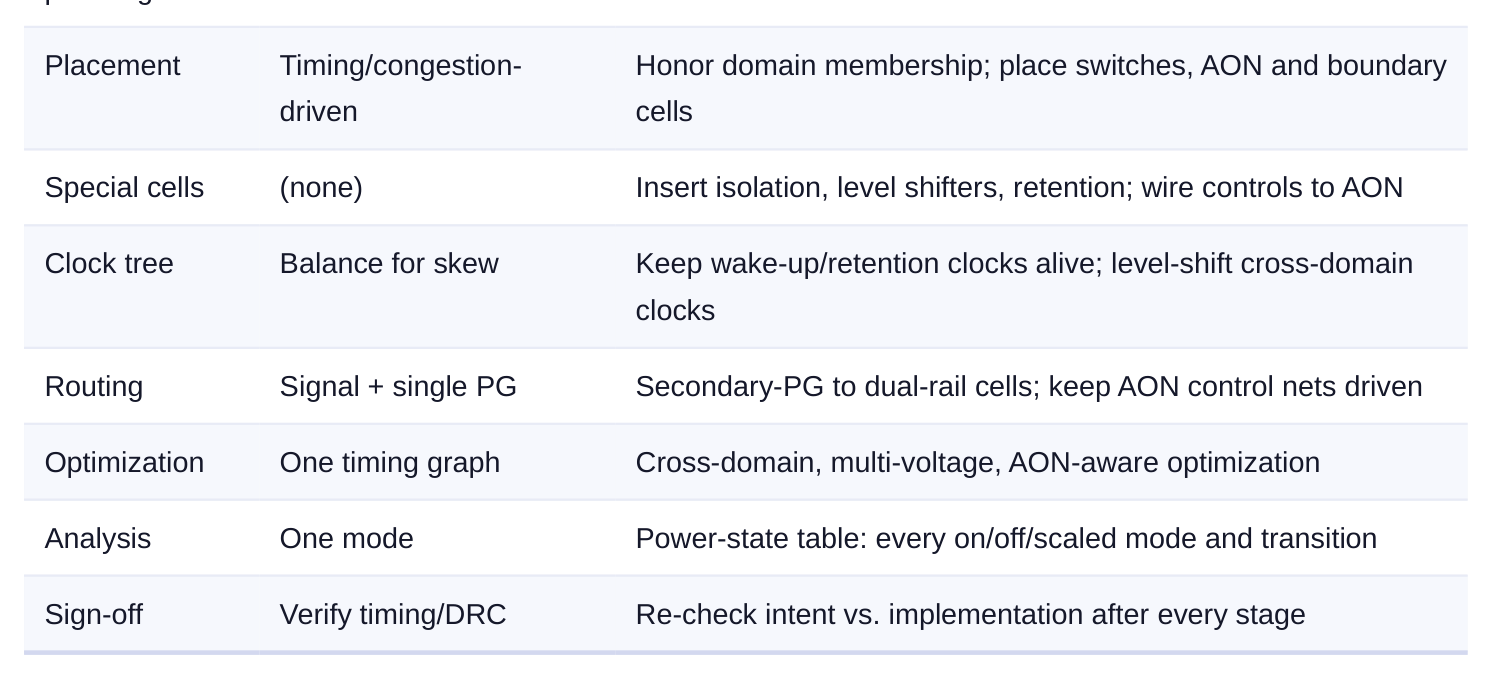
Stage-by-Stage Summary
| Stage | Normal job | Low-power addition |
|---|---|---|
| Setup | Read netlist + libraries | Read and commit power intent (UPF/CPF) |
| Floorplan | Place macros, define | Define voltage areas; commit switch plan and inrush ordering |
core
Power One PG mesh Always-on mesh + switched mesh + multi-voltage rails
Generic Command Flow Sketch
read_power_intent   -file design.upf
commit_power_intent
create_voltage_area -domain CPU_DOMAIN -coords $cpu_box
plan_power_switches -domain CPU_DOMAIN -style grid -enable_chain ordered
create_power_mesh   -net VDD_AON -always_on true
create_power_mesh   -net VDD_SW_VIRT -source switch_out
place_design        -honor_power_domains true
insert_isolation_cells
insert_level_shifters
insert_retention
build_clock_tree    -across_power_domains true -aon_buffers true
route_special       -secondary_pg true
route_signal
optimize_design     -multi_voltage -aon_aware
analyze_modes       -table PST
check_power_intent                ;# the final gate — and the per-stage gate
Interview Q&A
Because floorplan, placement, and power planning all make irreversible structural decisions that depend on knowing the domains. Voltage areas, the switch plan, and the always-on mesh are all derived from intent. If you defer it, the tool treats the design as single-rail, places cells in the wrong regions, and builds one mesh — and unwinding that at routing is far more costly than committing intent at the start.
you look? Trace the supplies and controls. The retention cell's retention supply must be always-on; if it was connected to the switched rail, the stored state dies with the domain. Next check the save/ restore control signals — they too must be driven from always-on logic with correct timing relative to the switch enable. Finally confirm the power-state table's transition sequence (isolate, save, switch off; switch on, restore, de-isolate) was honored during analysis.
Certain low-power cells — level shifters, always-on cells inside a switchable region, and some isolation cells — have a second supply pin that must connect to a different rail (typically the always-on rail) than the bulk supply of the area around them. Secondary PG routing pulls that second rail to those specific pins without shorting it to the switched supply. Skipping it leaves those cells unpowered exactly when they are needed.
many legal operating states, and a path or a check can pass in one and fail in another. A voltagescaled mode is slower; an off-domain changes what is isolated; mode transitions stress the boundary cells in ways no static mode shows. The power-state table enumerates the real modes, and sign-off
must close timing, IR drop, and EM across all of them — plus the transitions — not just the fullperformance corner.
Key Takeaways
- A single-supply flow assumes one always-on rail; low power breaks that assumption at every stage, so each stage gets explicit special handling.
- Power intent (UPF/CPF) is read and committed up front, then threaded through floorplan, placement, clock, routing, and optimization.
- The physical additions are concrete: voltage areas, a switch plan with inrush control, an always-on mesh plus switched/multi-voltage meshes, domain-aware placement, and inserted isolation/level- shifter/retention cells.
- Always-on continuity is the recurring failure point — clocks that must stay alive, control signals, secondary-PG pins, and retention supplies all must remain powered when their region is off.
- The power-state table turns "the design" into many modes; all of them, and their transitions, must close in analysis.
- Trust comes from re-checking intent against implementation after every stage, not only at sign- off, so divergence is caught where it is created.
Comments
Leave a Reply