 ChipBuddy
← Home
ChipBuddy
← Home
Analyzing & Fixing Signal Electromigration
Analyzing and Fixing Signal Electromigration (EM) Violations
Timing closure gets all the glory, but a chip that passes setup and hold can still fail in the field eighteen months after tapeout because a thin signal wire slowly atomized itself. That slow-motion failure mechanism is electromigration, and at advanced nodes it has quietly become one of the gating sign-off checks for the routing and postroute teams. This chapter walks through what signal EM actually is, where the tool finds violations, how you constrain it, and the concrete repair playbook — wire widening through non-default rules, redundant vias and EM-aware via ladders, current-density reduction, and layer promotion — all framed inside the analyze → fix → re-verify loop you will run dozens of times before sign-off.
What Signal EM Is and Why It Matters
Electromigration is the gradual transport of metal atoms caused by the momentum exchange between flowing electrons and the metal lattice. When current density in a wire or via gets high enough, electrons literally knock copper atoms downstream over time. Atoms pile up in some places (hillocks, which can short to a neighbor) and deplete in others (voids, which grow until the wire becomes an open). The result is a reliability failure that does not show up at time-zero testing — it shows up as a field return after the part has been running hot for months or years.
The governing intuition is Black's equation: mean time to failure scales inversely with current density squared and exponentially with temperature. Two things follow immediately. First, EM is a current- density problem, not a current problem — a wire carrying a given current is fine if it is wide enough and in trouble if it is thin. Second, EM is acutely temperature-sensitive, which is why sign-off is run at the worst-case (highest) operating temperature corner, not the slow timing corner you might expect.
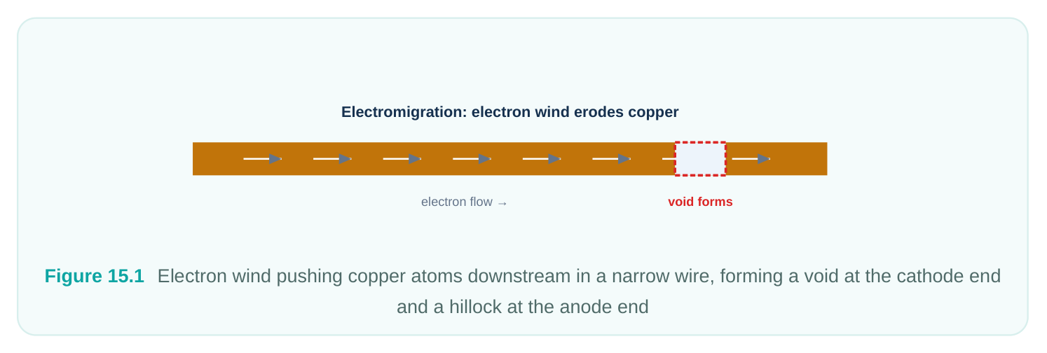
Why this matters now and not twenty years ago comes down to scaling. As metal pitches shrink, wire cross-sections shrink with them, so the same current produces a much higher current density. Meanwhile the maximum current density a wire can tolerate (Jmax) actually drops at finer geometries because of grain-boundary and liner effects. Add FinFET drive strengths that push more current per cell and you have a squeeze from both sides. On a 32nm design EM was something you spot-checked on power straps; at 6nm/4nm signal EM on ordinary logic nets is a first-class routing constraint that shapes how you route from the start. Signal EM splits into a few physical modes that the foundry rule deck distinguishes:
| EM mode | Driven by | Typical offender | Primary fix lever |
|---|---|---|---|
| Average (DC) | Time-averaged current, | Power/ground taps, always- | Widen wire, layer |
| EM | unidirectional flow | on nets | promotion |
| RMS (AC self- | Joule heating from switching | High-frequency clock and | Widen wire, reduce |
| heat) | current | high-toggle data | frequency/load |
| Peak | Instantaneous current spike (transient) | Wide drivers, large fanout edges | More/larger vias, lower drive |
Signal nets are dominated by RMS and peak limits because they switch bidirectionally; the average term often cancels. That distinction matters when you read reports — a net failing RMS needs a different remedy than one failing average.
Where Signal EM Violations Live
Before fixing anything, build a mental model of where the tool will flag problems, because the violations cluster in predictable places. Current density is highest where current is concentrated into small cross-sections, so the usual suspects are:
- High-toggle, high-fanout nets. Clock nets, clock-gating enables, scan-enable, reset, and fast data buses switch constantly and drive large loads. They carry the most RMS current.
- Driver output pins and the first wire segment. The total net current funnels out of one driver, so the segment closest to the output pin sees the highest density before the net branches.
- Single vias on high-current paths. A via is a tiny vertical cross-section and is almost always more EM-limited than the wires it connects. A lone via on a clock net is the canonical violation.
- Narrow default-width routing on long high-current nets. Min-width metal carrying near-Jmax current.
- Pin access and via-to-pin transitions where wide upper metal necks down to reach a standard- cell pin. EM via ladder — wide base, tapering up M6 M5 M4 M3 M2 M1 high-current pin Figure 15.2 A clock net fanning out, with red hotspots on the driver-pin segment and the single vias at each branch tap The practical takeaway: EM and signal integrity correlate. The nets you already worry about for crosstalk and slew are largely the same nets that will light up in the EM report. That overlap lets you fix several problems with one routing rule.
Setting Signal EM Constraints
The tool needs three ingredients to check signal EM: the physical Jmax/Imax limits per layer (from the technology and the EM rule files supplied with the library/PDK), the operating temperature, and accurate switching activity so it can compute RMS and average currents. The limits arise from the tech file and the dedicated EM constraint files; your job is mainly to point the tool at the right temperature corner and feed it credible toggle data.
# Enable signal EM analysis and point at the foundry EM rules
set_tool_option -name rail.em.enable_analysis -value true
set_tool_option -name rail.em.temperature -value 125
# Use real activity, not a blanket default, for RMS/average accuracy
read_saif -instance_name top ../sim/top.saif
set_switching_activity -toggle_rate 0.2 -static_probability 0.5 \
[get_nets -hierarchical *]
# Tie current calculation to the worst-case (highest-temp) corner
set_parasitic_parameters -early_spec rcworst -late_spec rcworst
A word on activity: EM is only as trustworthy as the toggle rates behind it. If you let the tool assume a default 18% toggle on every net, you will simultaneously under-report the genuinely hot clock nets and over-report sleepy nets, wasting area chasing phantom violations. Back-annotate a SAIF or VCD from a representative functional simulation wherever you can, and apply realistic per-net rates to clocks (which can effectively toggle at the clock frequency) versus quiet config nets. You also generally want EM checked at the temperature corner where Jmax is most punishing — the maximum junction temperature your spec allows. Setting rail.em.temperature to that value (e.g. 125 C) keeps the check conservative.
Analyzing: Running the Check and Reading the Report
With constraints in place, run the analysis and pull a report you can triage. Sort by the worst margin first; a violation that is 280% over limit needs a structural fix, while one at 96% might close with a single extra via.
# Run signal EM analysis across the design
analyze_rail -nets [get_nets -hierarchical *] -voltage_name VDD
# Report signal EM, worst offenders first, split by layer and type
report_em -type signal -nets [get_nets -hierarchical *] \
-sort_by violation -max_nets 200 > reports/sig_em.rpt
# Drill into one net to see which segment / via is failing
report_em -type signal -nets [get_nets clk_root] -verbose
A signal EM report is organized around three numbers per object: the actual current density the tool computed, the allowed limit for that layer and EM mode, and the ratio between them. Anything above 1.0 (or 96%) is a violation. Read the columns to learn which mode failed — a wire over its RMS limit is a self-heating problem you fix by widening; a via over its peak limit is a structural problem you fix by adding redundancy.
| Report field | What it tells you | How it steers the fix |
|---|---|---|
| Object type (wire / via) | Where the bottleneck is | Vias → redundancy/ladders; wires → width/ |
promotion
| EM mode (avg / RMS / | The dominant physical | RMS → widen; peak → more vias / lower drive |
|---|---|---|
| peak) | mechanism | |
| Layer | Which metal/via layer is | Promotion target candidate |
limiting
| Actual vs. limit ratio | Severity of the violation | Prioritize and pick aggressiveness of fix |
|---|---|---|
| Net / driver pin | The owner of the violation | Group fixes by net for NDR application |
Group the results: a bucket of single-via peak violations is solved wholesale by an EM via-ladder pass, while a bucket of wire RMS violations is solved by tagging those nets to a wider non-default rule and rerouting.
Fixing Strategy 1: Widen Wires with Non-Default Rules
The most direct way to lower current density is to give the current more cross-section — a wider, and sometimes thicker, wire. You do not edit individual segments by hand; you define a non-default routing rule (NDR) and assign the offending nets to it, then let the router rip up and reroute them at the larger width. Chapter 5 covers NDR mechanics in depth; here we use them as an EM lever.
# A 2x-width rule for EM-critical signal nets
define_routing_rule EM_2W \
-widths {M3 0.10 M4 0.10 M5 0.14 M6 0.14} \
-spacings {M3 0.06 M4 0.06 M5 0.08 M6 0.08} \
-taper_distance 0.5
# Apply the rule to the EM-failing nets, then reroute just those nets
apply_routing_rule [get_nets {clk_root reset_n data_bus[*]}] -rule EM_2W
route_net_group -nets [get_nets {clk_root reset_n data_bus[*]}] -
reuse_existing_global_route false
Doubling width roughly halves current density, which clears most marginal RMS violations and helps average mode too. The cost is area and routing resource: wide-and-spaced wires consume tracks fast, so apply NDRs surgically to the nets the report actually flags rather than blanketing a whole bus. Note the -taper_distance — without tapering, a wide wire that must neck down to a min-width pin recreates a hotspot right at the pin, so let the rule taper gracefully into the connection.
Fixing Strategy 2: Redundant Vias and EM-Aware Via Ladders
Vias are the chronic EM weak point. A single cut between two layers has a tiny conductive crosssection, so it hits its current limit long before the wires on either side do. The fix is redundancy: replace
single cuts with double or multi-cut via arrays so the current splits across multiple parallel paths, lowering the density through each cut. For a layer transition that spans several metals — say a clock tap climbing from M2 up to M6 — you want redundancy at every layer in the stack, not just one. That stacked, multi-cut structure is a via ladder, and the tool can insert them automatically against an EM-specific rule. The via-ladder rule machinery itself is introduced in Chapter 5; what is special for EM is that the rule is sized so each rung carries current density under its limit for the expected net current.
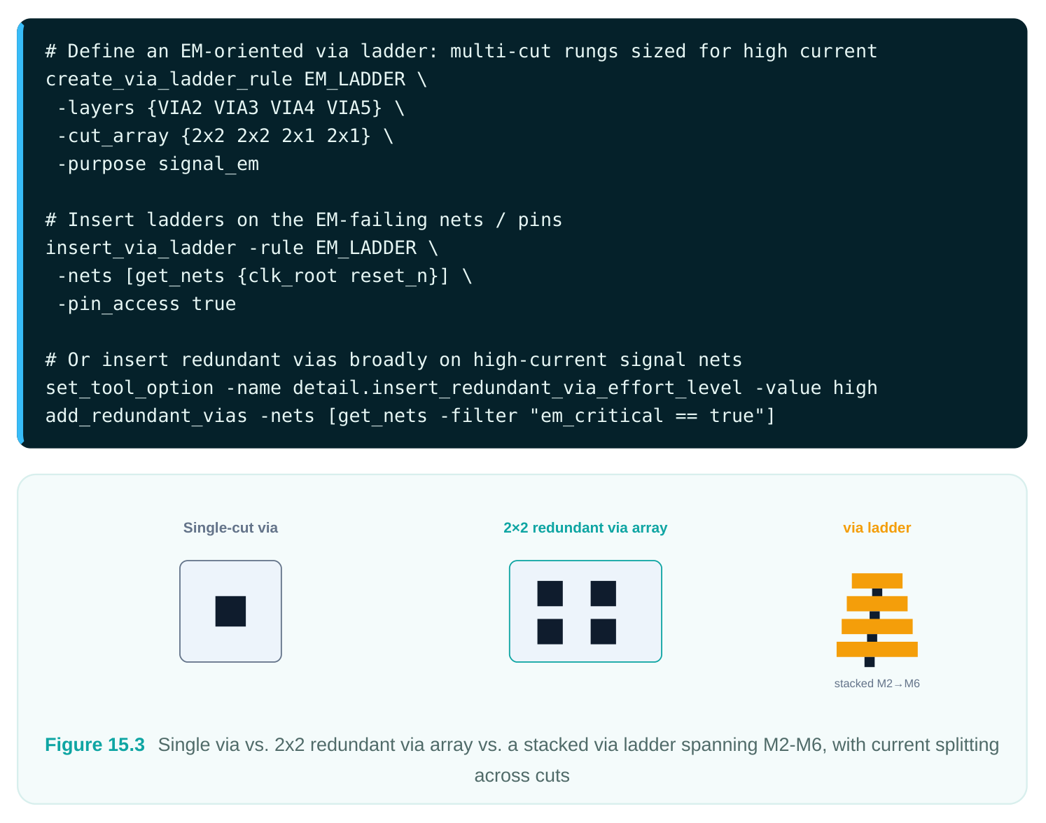
The trade-off with via redundancy is that arrays need landing area on both metals, so on congested layers the tool may not be able to place a full 2x2. That is why ladder rules let you taper the cut count up the stack ( 2x2 on lower, tighter layers may be infeasible; reserve the big arrays for the layers with room). Always re-DRC after ladder insertion — a too-aggressive array can create min-spacing or enclosure violations.
Fixing Strategy 3: Reduce Current Density at the Source
Widening and redundancy treat the symptom by adding cross-section. You can also attack the cause by lowering the current the net carries in the first place. Lower current means lower density for free, no extra area.
Levers here include downsizing or splitting the driver (a smaller driver pushes less peak current, though watch timing), buffer insertion to break a long high-current net into shorter segments each carrying less current, and load reduction — fewer or smaller sink pins on a net cut the current it must deliver. On clock nets, balancing the tree so no single segment carries the whole clock current is itself an EM measure. These overlap heavily with timing and SI fixes, which is the point: a buffer added for slew often retires an EM violation as a side effect.
# Break high-current nets with buffers to reduce per-segment current
set_tool_option -name opt.em.fix_enable -value true
insert_buffer -nets [get_nets {long_hi_current_net}] -lib_cell BUFx8
# Let postroute opt consider EM alongside timing during ECO
set_tool_option -name opt.common.enable_em_aware_optimization -value true
postroute_opt -incremental
The caution: every source-side change perturbs timing. Run these inside the timing-driven ECO flow so the tool re-times as it goes, rather than blindly downsizing drivers and reopening setup violations.
Fixing Strategy 4: Layer Promotion
Higher metal layers are thicker and wider by construction, so they tolerate much more current — their Jmax limits are far higher than thin lower metals. Layer promotion routes (or reroutes) a high-current net up onto these robust upper layers instead of leaving it on EM-fragile M1/M2. A clock trunk that violates badly on M3 may pass comfortably on M6 with no width change at all, simply because the layer itself is built for it.
# Force EM-critical nets onto upper, EM-robust layers
apply_routing_rule [get_nets clk_root] -min_routing_layer M5 -max_routing_layer M7
route_net_group -nets [get_nets clk_root] -reuse_existing_global_route false
Promotion pairs naturally with via ladders — moving up the stack requires a robust ladder to climb the layers without creating a new via bottleneck on the way up. The cost is upper-layer congestion, which is shared with power and clock distribution, so promote selectively.
The Analyze → Fix → Re-Verify Loop
EM closure is iterative, never one-shot. Each fix changes geometry, parasitics, and sometimes timing, which can shift or even create violations elsewhere. The disciplined loop is:
- 1. Analyze. Run
analyze_rail/report_em, bucket violations by object type and EM mode. - 2. Fix. Apply the matching remedy per bucket — NDRs for wire RMS, ladders/redundant vias for via
peak, source-side changes for the stubborn ones, promotion for the severe wire violations.
- 3. Re-route / ECO. Let the router realize the changes (
route_net_group,postroute_opt -
incremental ).
- 4. Re-verify. Re-run EM analysis and re-run DRC and STA, because every fix can break a neighbor.
- 5. Repeat until the EM report is clean at the worst-case corner.
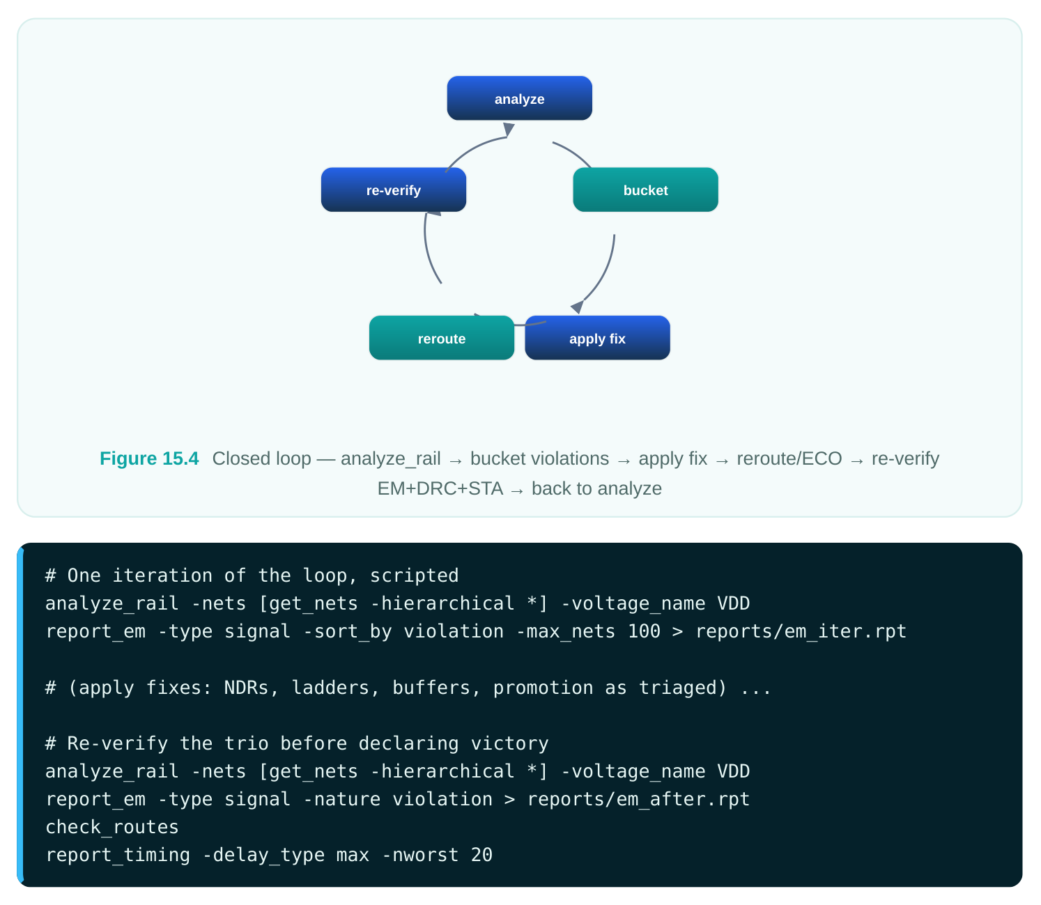
The trap to avoid is fixing in isolation. Inserting a fat via array can violate spacing; widening a net can push a neighbor into a crosstalk fail; downsizing a driver can reopen setup. Treating DRC and STA as part of EM re-verification — not as separate downstream steps — is what keeps the loop from oscillating. Converge by attacking the worst-margin violations first; clearing the 280% offenders often relieves congestion that lets the marginal ones close on their own.
Interview Q&A
corner? Because EM lifetime is dominated by temperature. Black's equation makes mean-time-tofailure fall exponentially as temperature rises, and the allowed current density (Jmax) drops at higher temperatures. The most pessimistic EM scenario is therefore the maximum operating junction temperature, regardless of which corner is worst for setup or hold. We set rail.em.temperature to the spec's max and analyze there to stay conservative.
add vias? RMS failure on a wire is a self-heating / cross-section problem, so the lever is to increase the wire's cross-section — widen it via a non-default rule, or promote it to a thicker upper layer. Adding vias does nothing for a wire-segment violation because the bottleneck is the wire's own width, not the layer transition. Matching the fix to the reported EM mode and object type is the whole game; adding vias to a wire RMS violation just burns area and DRC effort with no benefit.
ladder help? A single via cut has a tiny conductive cross-section compared to the wires it joins, so for a given current it sees far higher current density and hits its limit first. A via ladder replaces single cuts with multi-cut arrays at every layer of a multi-metal transition, splitting the current across parallel cuts so each carries a fraction of the total. It also gives redundancy — if one cut voids, the others still conduct. For EM specifically we size the array cut counts per layer so each rung stays under its density limit.
went wrong and how do you prevent it? EM fixes are not free — wider wires consume tracks and spacing, fat via arrays need enclosure/landing area, and any geometry or driver change perturbs parasitics and timing. The new violations mean the fixes were applied without folding DRC and STA into the verification step. The prevention is to treat re-verification as analyze EM plus check_routes plus report_timing every iteration, apply NDRs surgically to only the reported nets, use tapering so wide wires neck into pins cleanly, and run source-side fixes inside the timing-driven ECO flow so the tool re-times as it edits.
Key Takeaways
- Signal EM is a current-density and temperature problem: electron wind erodes metal over time, so it is a reliability/lifetime check, not a time-zero one, and it is sign-off-critical at advanced nodes where wires are thin and Jmax is low.
- Violations cluster on high-toggle/high-fanout nets, driver-output segments, and single vias; vias are the chronic weak point.
- Constrain the check with real switching activity (SAIF/VCD), the foundry EM limits, and the maximum-temperature corner — bad activity data yields useless reports.
- Match the fix to the reported EM mode and object: NDR widening or layer promotion for wire RMS/ average, redundant vias and EM via ladders for via peak, and source-side reduction (buffering, driver sizing, load cuts) to attack current at its origin.
- Close EM in a loop — analyze, bucket, fix, reroute, then re-verify EM together with DRC and STA — and always tackle the worst-margin violations first to relieve congestion for the rest.
Comments
Leave a Reply