 ChipBuddy
← Home
ChipBuddy
← Home
Shared Clock-Data Concerns & Cell Halos
Halos
Clock tree synthesis likes to pretend the world divides cleanly into two camps: nets that carry the clock, and nets that carry data. Reality is messier. A single physical net can feed a clock pin on one instance and a data pin on another. A combinational cell can sit on the clock path while also fanning out into logic. Clock-gating cells straddle both worlds by definition, taking a data-driven enable and producing a gated clock. Frequency dividers chop the clock and hand the result downstream as something that is part clock, part logic. When the CTS engine and the concurrent clock-data optimizer make decisions about these shared resources, they can either preserve function and timing faithfully, or they can corrupt it in ways that pass every structural check and fail in silicon. This chapter is about the seams between clock and data: where they touch, why those touch points are dangerous, and how to fence them off. We will also cover library-cell halos, a placement discipline that protects the large, sensitive cells the clock tree depends on. The two topics belong together because both are about respecting the special status of clock structures inside a flow that otherwise treats every cell as fungible.
Why Shared Resources Need Special Handling
The balancing math behind CTS assumes it knows what each endpoint is. A sink is something whose arrival time should match the other sinks in its skew group. A clock source is something whose delay should be propagated forward and balanced against. When a net or cell is shared, that assumption breaks in one of two ways. First, misclassification: the engine may treat a shared pin as pure clock and balance to it, or treat it as pure data and ignore it, when neither is fully correct. Balancing to a data pin that merely happens to receive a clock-derived signal can waste buffering and distort skew where it does not matter. Ignoring a genuine clock fanout can leave a real sink unbalanced. Second, double-counting or delay corruption: if a cell appears on the clock path and the optimizer also sees it as logic, the same delay segment can be accounted for twice, or sizing decisions made for data timing can change the clock insertion delay in unexpected ways. The classic failure is an enable path on a clock-gating cell that gets optimized for setup as if it were ordinary logic, shifting the effective clock edge at the gate output.
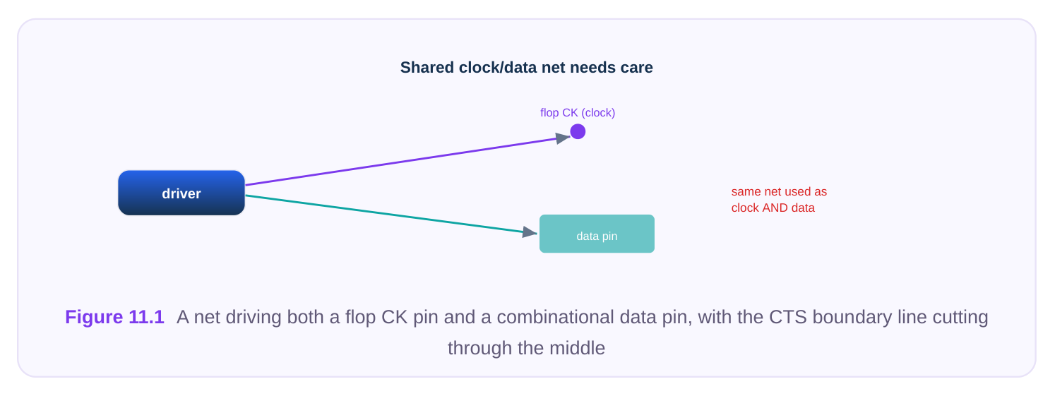
The defensive posture is always the same: make the tool's model of clock-versus-data match the designer's intent, and where the two genuinely overlap, tell the tool explicitly how to treat the overlap rather than letting heuristics guess. It helps to keep a mental taxonomy of how sharing arises. There is structural sharing, where the netlist itself connects one driver to a mix of clock and data pins; this is usually intentional and the designer knows about it. There is incidental sharing, where a cell that began life as logic ends up on the clock path because of how the clock was traced through combinational gates; this often surprises people. And there is optimization-induced sharing, where the concurrent clock-data optimizer, hunting for the best timing, decides to reuse a buffer or resize a cell in a way that ties clock and data together that were previously separate. The first kind you manage by declaration. The second you catch by reviewing the traced clock network. The third you prevent by constraining what the optimizer is allowed to touch. Knowing which category you are dealing with tells you which lever to pull. The table below catalogs the common shared situations, the risk each carries, and the standard handling.
| Situation | Risk | Handling |
|---|---|---|
| Net feeds a CK pin and a data | Engine balances to wrong | Define the data side as a non-stop/ |
| pin | endpoint; wasted buffering | exclude pin; let clock spec own only the |
CK fanout
| Combinational cell on clock | Sizing for data setup shifts | Mark cell as clock-path; freeze or |
|---|---|---|
| path also drives logic | clock insertion delay | constrain its sizing during CTS |
| Clock-gating cell (enable + | Enable path optimized as data | Treat as clock-tree cell; balance gated |
| clock in, gated clock out) | corrupts gated edge | and ungated sinks together |
| Divider / non-unate element | Edge polarity and period | Declare as clock-tree cell; create separate |
| on clock | change confuse skew | skew groups across the divide |
grouping
Buffer shared between two Cross-domain skew coupling Forbid reuse; force per-domain buffering
| Data buffer pulled into clock | Unintended clock structure, | Lock data cells out of clock-tree cell list |
|---|---|---|
| during opt | hard-to-trace skew |
Clock-Gating Cells in the Tree
A clock-gating cell is the most common shared structure you will meet. It has a clock input, an enable input fed by control logic, and a gated-clock output that drives a bank of registers. The output is unambiguously clock. The enable input is data. The cell sits squarely on the clock path, and its insertion delay matters as much as any buffer's. Two things must hold for a gated tree to be correct after CTS. First, the enable timing must be met: the enable must be stable around the gating cell's clock edge so the gate does not chop a partial pulse. This is a setup/hold relationship at the gate, checked against the clock arriving at the gate, not against the gated output. Second, gated and ungated sinks must stay balanced. Registers behind a gate and registers driven directly from the same clock node should still share a skew target, otherwise launch/capture pairs that span the gate boundary will see artificial skew.
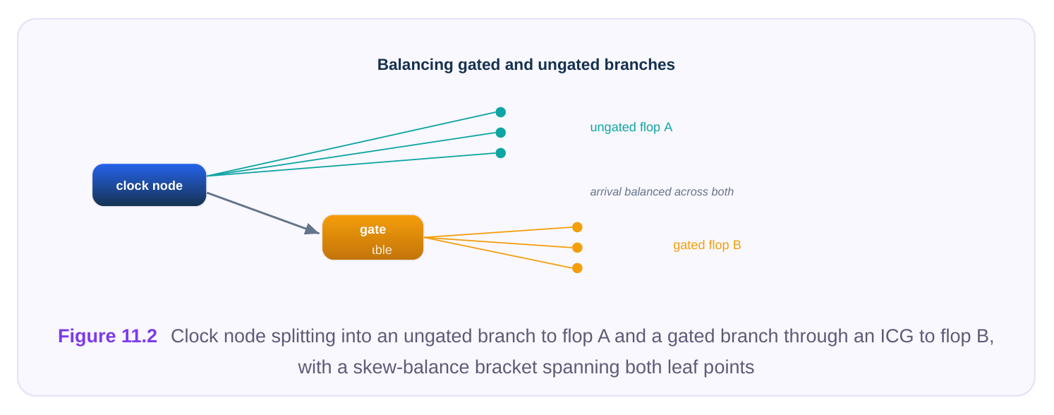
The practical instruction set tells the engine that the gating cell is part of the tree and that its downstream sinks belong to the same balancing scope as the sinks that bypass it.
# Treat clock-gating cells as legitimate clock-tree elements
set_clock_tree_options -clock CLK \
-allow_gating_cells true \
-balance_across_gates true
# Mark a specific gate instance for clock-path handling
set_attribute [get_cells u_icg_bank3] clock_path_handling gated_clock
# Keep the enable arc checked against the gate's clock pin,
# not optimized away as ordinary combinational logic
set_clock_gate_enable_check -gate [get_cells u_icg_bank3] \
-mode preserve_enable_arc
The enable path itself is usually best fixed by upstream data optimization rather than by CTS. The point of the CTS-side directive is defensive: keep the engine from sizing or restructuring the enable in a way that moves the gated edge. A subtle point that trips up newcomers concerns where the gating cell's insertion delay is counted. The delay from the clock root to the gate's clock input is shared by every register behind that gate, plus it adds to the delay seen by the gated leaf nodes. If the engine balances the gated bank to the same target as the ungated registers, it must compensate for the gate's own delay inside the gated branch, typically by shortening the buffering after the gate or lengthening it before. When this compensation is done correctly the leaf arrival times line up; when the gate is treated as an opaque sink rather than an in-path element, the compensation is missed and the gated bank arrives systematically late. Always confirm, in the post-CTS report, that the gate's downstream leaves landed in the same skew window as their ungated peers. There is also a planning dimension. Placing the gating cell well matters as much as buffering it correctly. A gate dropped far from the register bank it drives forces a long gated-clock route, which adds latency that must then be compensated on the ungated side, inflating the whole group's insertion delay. Good practice is to place the gate close to the centroid of its register bank so the gated route is short and the balancing job stays small.
Non-Unate and Dividing Elements
A buffer or inverter is unate: a rising input edge produces a predictable output edge, and the engine can reason about delay per edge cleanly. Dividers, multiplexers selecting between clocks, and certain XOR-based clock logic are non-unate or edge-modifying. They change the period, the duty cycle, or the relationship between input and output edges. Balancing across such an element is meaningless in the simple sense, because the thing on the far side is a different clock. The correct treatment is to break the balancing scope at the dividing element. Sinks upstream of the divider balance to the source period; sinks downstream balance to the divided period. The insertion delay of the divider is propagated, but its output is treated as a new clock root for grouping purposes. If
you let the engine try to skew-match a flop running at the divided rate against a flop running at the source rate, the numbers it produces will be technically consistent and functionally irrelevant.
# Declare a divider output as a generated clock root and
# stop balancing from crossing the divide
create_generated_clock -name CLK_DIV2 \
-source [get_pins u_div/CK] -divide_by 2 \
[get_pins u_div/Q]
set_clock_tree_options -clock CLK_DIV2 -balance_scope independent
set_attribute [get_cells u_div] clock_path_handling divider
Multiplexed clocks deserve a note: when a mux selects between two clock sources, both source-side trees and the mux-output tree must each be coherent, and the mux itself is a shared element whose two data-like select and input pins must not be treated as ordinary logic. Mark the mux as a clock-tree cell and constrain its sizing. The select line is genuinely data, but it is data that gates which clock reaches the downstream logic, so it carries its own timing relationship that the engine should not casually optimize. In multi-mode designs the same mux output may be a different clock in different functional modes; each mode's clock must be defined and balanced on its own terms, and the engine must understand that only one is active at a time so it does not try to satisfy contradictory balancing targets simultaneously.
Library-Cell Halos in CTS
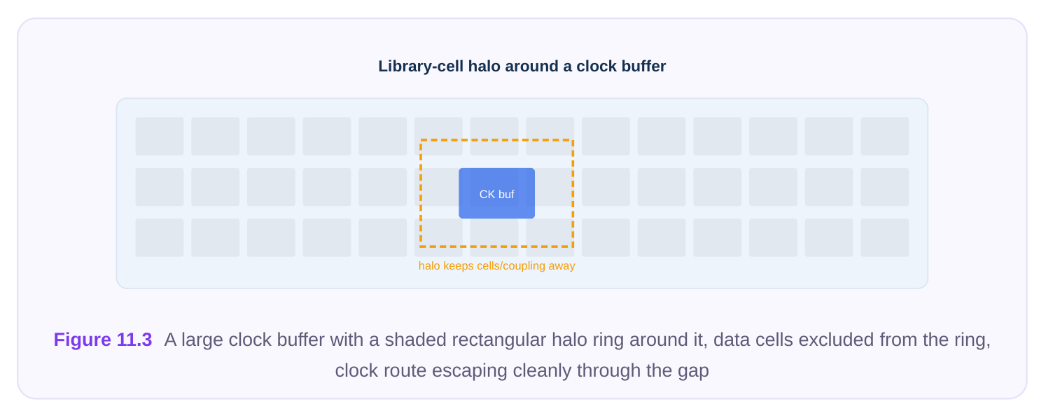
A halo is a keep-out region around a cell instance that prevents other instances from being placed too close. In the data world halos protect macros. In CTS they protect the cells the clock tree leans on most heavily: large clock buffers and inverters near the top of the tree, clock-gating cells driving wide register banks, and dividers whose output edges must stay clean. There are three reasons to halo a clock cell.
- 1. Pin access. A large clock buffer carries high current and often needs multiple pin contacts and
wide straps. If logic crowds right up against it, the router struggles to reach the clock pins, and you get detours that add latency and variation.
- 2. Coupling reduction. Clock nets switch every cycle and are aggressive aggressors. A halo creates
physical separation between the clock cell's output and nearby sensitive data nets, lowering crosstalk-induced jitter.
- 3. Routing relief. Clock routing often uses preferred layers and wider, shielded wires. A halo reserves
the room those wires need to escape the cell without fighting local data congestion.
The table below maps halo use cases to the problem they solve and a typical sizing intuition.
| Halo use case | Problem addressed | Typical sizing intuition |
|---|---|---|
| Large top-level clock | Pin access, high drive | Wider on the output side, asymmetric toward |
| buffer | current | routing direction |
| Clock-gating cell at bank | Enable + clock pin entry | Modest uniform ring; protect both signal pins congestion |
| Divider / PLL-adjacent | Coupling, edge integrity | Generous ring; pair with shielding |
clock cell
Clock mux Multiple wide inputs to Larger on input side
Leaf-level small clock Usually none needed No halo; halos here waste area Halos come in soft and hard flavors, and the distinction matters. A hard halo is an absolute keep-out: no other instance may be legalized inside it, period. A soft halo is a placement discouragement: the placer avoids the region if it reasonably can but may fill it under congestion pressure. Hard halos give the strongest protection but are the most likely to cause legalization grief in a tight floorplan; soft halos are gentler but offer no guarantee. The usual approach is hard halos on the few truly critical clock cells where coupling or pin access is non-negotiable, and soft halos or none elsewhere. Halos are applied per cell instance or per library cell type. A common pattern is to halo by master so that every instance of a chosen large clock buffer master inherits the keep-out automatically.
# Apply a keep-out halo to all instances of a large clock buffer master
set_cell_halo -cells [get_cells -filter "ref_name == CLKBUFX16"] \
-left 0.8 -right 1.2 -top 0.8 -bottom 0.8
# Halo a specific clock-gating instance, protecting both signal pins
set_cell_halo -cells [get_cells u_icg_bank3] \
-uniform 0.6
# Halo a divider with extra room on the output side for shielded routing
set_cell_halo -cells [get_cells u_div] \
-left 0.5 -right 1.0 -top 0.5 -bottom 0.5
Halos cost area, so they are a targeted tool, not a blanket one. Reserve them for cells where pin access or coupling is genuinely at risk. Halo every clock buffer in the design and you will inflate area and congestion for no benefit, because small leaf buffers do not have the access or coupling problems that justify the keep-out.
Density and Placement Controls for Clock Cells
Beyond halos, the engine offers coarser controls over where and how densely clock cells are placed. Two are worth knowing for interviews. The first is a local density cap for clock cells: a ceiling on how tightly clock buffers and gates may pack within a region. Clustering clock cells creates local hotspots of switching current and heat, and dense clusters fight clock routing. A density ceiling spreads them out enough to route and to stay thermally sane. The second is placement guidance or blockage that steers clock cells toward or away from regions. You may want clock buffers kept out of a congested datapath, or pulled toward a spine where the clock distribution lives. Soft blockages discourage placement without forbidding it; hard blockages forbid it outright.
# Cap clock-cell density in a region to avoid hotspots
set_clock_cell_density -region {120 200 480 560} -max_density 0.55
# Discourage clock cells from a congested datapath (soft blockage)
create_placement_blockage -type soft_clock \
-boundary {300 100 360 700}
# Pull clock distribution cells toward a defined spine
set_clock_tree_options -clock CLK -placement_bias spine -spine_x 400
These controls interact with halos: a tight density cap plus large halos can over-constrain a small region and cause placement legalization to fail or push cells far from their ideal location, hurting latency. Tune them together, not in isolation. A worked intuition helps. Suppose a region needs twelve clock buffers to distribute the clock, each wants a generous halo, and you have also set a low clock-cell density ceiling there. The placer now
has three constraints fighting one another: it must fit twelve cells, keep them apart by their halos, and stay under the density cap. If the region is small, those constraints are jointly infeasible, and the legalizer will either fail outright or scatter the buffers far from where the tree wants them, lengthening routes and adding the very latency and variation the controls were meant to reduce. The lesson is that placement controls for clock cells are a budget, not a wish list. Decide what each region can physically hold, then spend halos and density caps within that budget rather than stacking every protection everywhere.
Avoiding Shared-Resource Pitfalls
The failures in this chapter rarely announce themselves. Three habits prevent most of them. Audit the clock-tree cell list. The engine works from a list of which library cells it is allowed to use and treat as clock structure. A data buffer that drifts onto this list can be pulled into the clock during optimization, creating phantom clock structure that is hard to trace. Conversely, a clock cell missing from the list may be left unbalanced. Review the list explicitly. Exclude shared data pins from balancing. When a net legitimately feeds both clock and data, name the data pins as exclude or non-stop points so the clock spec balances only the true clock fanout. Forbid cross-domain buffer reuse. A buffer feeding two clock domains couples their skew. Force per-domain buffering so each domain owns its structure.
# Restrict CTS to an approved clock-cell list; nothing else gets reused as clock
set_clock_tree_references -clock CLK \
-buffer_cells {CLKBUFX4 CLKBUFX8 CLKBUFX16} \
-inverter_cells {CLKINVX4 CLKINVX8}
# Exclude a shared data pin so balancing ignores it
set_clock_balance_exception -exclude_pins [get_pins u_mix/D]
# Forbid a buffer master from being shared across two clocks
set_clock_tree_options -clock CLK_A -exclusive_references true
set_clock_tree_options -clock CLK_B -exclusive_references true
Interview Q&A
it, and what goes wrong if it does not? Treat the clock fanout as the only balancing target and explicitly exclude the data pin from balancing, typically by marking it as a non-stop or exclude point. If the engine treats the data pin as a sink, it wastes buffering trying to skew-match an endpoint that has no skew requirement and may distort the real clock fanout. If it stops the clock spec at the shared net entirely, the true CK fanout goes unbalanced. The fix is to make the clock spec own only the genuine clock pins.
Registers behind a clock gate and registers fed directly from the same clock node frequently form
launch/capture pairs across the gate boundary. If you balance the two groups independently, you introduce artificial skew between them that shows up as setup or hold failures on those crossboundary paths. So they must share a skew target. The enable check is the setup/hold relationship of the gate's enable input relative to the clock arriving at the gate, ensuring the enable is stable around the edge so the gate never produces a runt clock pulse.
divider output is a different clock with a different period and possibly different edge relationships, so matching the arrival time of a flop on the divided clock against a flop on the source clock is functionally meaningless. Instead you break the balancing scope at the divider: declare the divider output as a generated clock root, balance source-side sinks to the source period and divided-side sinks to the divided period independently, and propagate the divider's insertion delay forward without trying to skew-match across it.
worth it on large top-level clock buffers, clock-gating cells at the entry of wide register banks, dividers, and clock muxes, where pin access, switching coupling, and shielded routing genuinely need reserved room. It is wasted on small leaf-level clock buffers, which have neither the pin-access nor the coupling problems that justify a keep-out, and where blanket halos just inflate area and congestion. Halos are a targeted protection, applied per critical master or instance, not a global policy.
Key Takeaways
- Shared clock/data resources break the engine's clean clock-versus-data model; the cure is to make the tool's classification match designer intent and to declare overlaps explicitly.
- Clock-gating cells are clock-tree elements: keep gated and ungated sinks in one skew scope, and protect the enable arc from being optimized as ordinary data.
- Dividers and non-unate elements end one balancing scope and begin another; declare the output as a generated clock root and balance the two sides independently.
- Library-cell halos protect large clock buffers, gates, dividers, and muxes by reserving room for pin access, coupling separation, and shielded routing; apply them surgically, not everywhere.
- Density caps and placement blockages steer clock cells away from hotspots and congestion, but interact with halos and must be tuned together to avoid over-constraining a region.
- Guard the clock-tree cell list, exclude shared data pins from balancing, and forbid cross-domain buffer reuse to prevent the silent functional and skew failures that shared resources cause.
Comments
Leave a Reply