 ChipBuddy
← Home
ChipBuddy
← Home
Clock Tree Concepts & Specifications
Before any synthesis engine can build a clock network, it needs a precise mental model of what it is balancing and against what. This chapter unpacks the vocabulary and the data structures that sit underneath every clock tree synthesis (CTS) flow: the tree itself, the objects on it, the skew groups that define balancing intent, and the structured specification that ties everything together. Get these concepts wrong and the tool will dutifully optimize the wrong thing — perfectly balancing endpoints that never needed balancing while ignoring the ones that did. Interviewers probe this area hard precisely because it separates engineers who run a script from engineers who understand what the script is asking the tool to do.
The objects the engine reasons about
A clock tree, at its simplest, is a directed structure that begins at a clock root (the definition point of a clock, typically a port or the output pin of a clock-generating cell), fans out through a hierarchy of buffers and inverters, and terminates at a set of sinks — the clock input pins of sequential elements like flip-flops, latches, and clock pins of memories or hard macros.
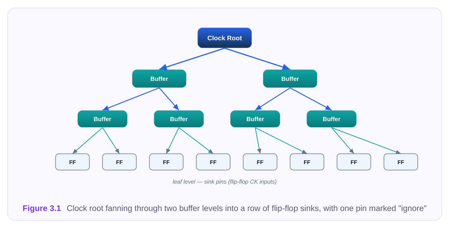
The engine treats the network as a tree it owns and is free to restructure. Everything between the root and the sinks — buffer sizing, buffer placement, the number of logic levels — is the engine's to decide, subject to the constraints you give it. The endpoints, however, fall into distinct categories that the engine must be told about explicitly:
- Sinks (balanced endpoints): Pins the engine must reach and balance. These are the leaves of the tree that participate in skew analysis. The vast majority of register clock pins fall here.
- Ignore pins: Pins the engine should drive (it must still deliver a clock signal to them) but should not balance. A classic example is the clock pin of a block that has its own internal clock distribution and only needs a clean arriving edge, not a latency-matched one.
- Exclude / stop pins: Pins where the engine should stop tracing the clock entirely. The clock does not propagate past this point as far as CTS is concerned — for instance, the data input of a clock gating cell, or a pin feeding a non-clock structure that you do not want buffered as clock. The distinction between ignore and exclude trips up many candidates. Ignore means "deliver the signal, but do not include this endpoint when computing skew." Exclude means "do not even traverse here; this is the edge of my tree." One is a balancing exception; the other is a topology boundary. A few subtler endpoint types round out the picture. A leaf pin on a macro may be both a sink and the entry point of a vendor-supplied internal tree with its own fixed insertion delay; the engine cannot restructure inside the macro, so it must model that internal delay and balance the external tree against it. Recognizing that the engine's freedom ends at certain pins — and that beyond them lies fixed, pre- characterized delay — is essential to predicting what the tool can and cannot fix.
Skew groups: why one balancing set is rarely enough
The single most important conceptual object in CTS is the skew group: a set of endpoints that must be balanced relative to each other. Skew is only meaningful within a group. Asking "what is the skew of this design?" is incomplete; the right question is "what is the skew within each balancing set?"
Why not throw every sink into one giant group? Because balancing endpoints that have no timing relationship is wasteful at best and harmful at worst. Consider two clock domains that never talk to each other — there are no launch/capture paths crossing between them. Forcing their latencies to match buys you nothing, yet it constrains the engine, burns buffers, and can degrade the skew you actually cared about within each domain. Worse, two endpoints might be intentionally offset (a deliberate useful-skew or a divided-clock relationship), and lumping them together would fight that intent. Skew groups are therefore derived from connectivity and timing relationships, not from physical proximity:
- Registers whose launch and capture edges are compared on the same timing path should share a balancing set, so that their relative arrival times are controlled.
- Registers in unrelated clock domains belong in separate groups.
- Endpoints on the same clock that feed independent, non-interacting logic can be split into separate groups if that helps the engine, though this is an advanced tactic. In practice, the grouping that a tool derives automatically is a starting point, not gospel. Automatic grouping is usually connectivity-driven: the engine walks the netlist, finds the sinks reachable from each root, and proposes one group per clock. That is correct often enough to be useful but blind to two things it cannot see from structure alone — functional exclusivity (clocks that share silicon but never run together, such as a functional clock and a test clock) and intentional offsets you have in mind. Refining the grouping is where engineering judgment enters. You merge groups that exchange data across domains, split groups whose sinks have no mutual timing paths, and remove endpoints that only need delivery. Each refinement should be defensible by pointing at a timing path (or the absence of one), never by hand-waving about "tidiness." A useful sanity check: for every pair of endpoints in the same group, you should be able to name a timing path whose closure depends on their relative arrival. If you cannot, the pair probably does not belong together.
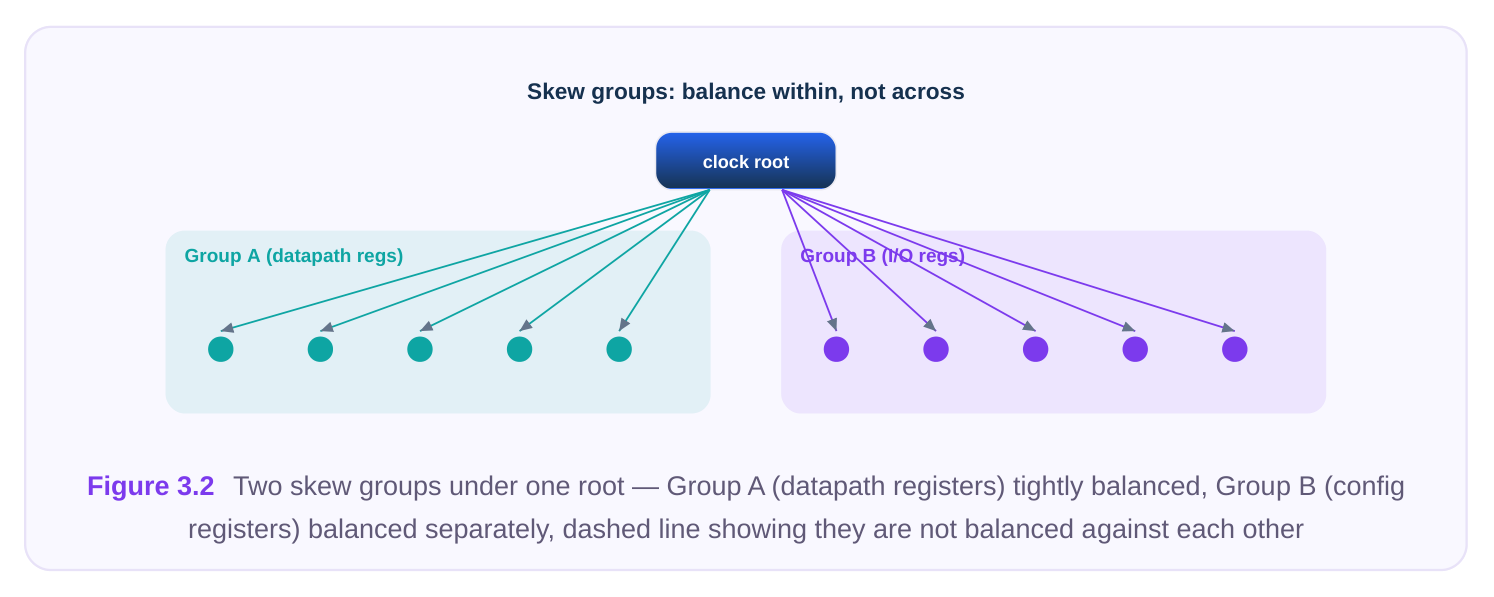
The table below summarizes the common kinds of skew groups you will encounter or define.
| Skew-group type | What it contains | Typical use |
|---|---|---|
| Intra-clock group | All balanced sinks of a single clock | Default; balance a domain against itself |
| Subgroup (split) | A subset of one clock's sinks balanced independently | Relax balancing where no timing path links the subsets |
| Inter-clock group | Sinks from two or more clocks balanced together | Domains that exchange data and must share a latency reference |
| Macro/boundary | Macro clock pins or block boundaries | Match latency to hard-macro internal trees or |
| group | treated as a set | to a parent block |
| Excluded set | Endpoints removed from any balancing | I/O-style or self-contained pins that only need |
delivery
Inter-clock balancing relationships
When data crosses from one clock to another, the relative latency of the two clocks at the crossing matters as much as the skew within each. Inter-clock balancing tells the engine which clocks must be balanced against which. If clock A launches data that clock B captures, and you want their insertion delays referenced to a common point, you place them in a shared balancing relationship so the engine equalizes (or deliberately offsets) their arrival times at the crossing. The engine cannot infer all of these relationships safely on its own. Two clocks may be structurally independent yet logically coupled through a path the engine cannot see without timing context — or two clocks may look related (shared root) yet be functionally exclusive (never active together). The specification is where you make this explicit: balance these clocks together, ignore that pair, keep this third one standalone. There is also a quality dimension to inter-clock balancing. When two trees of different natural depth must share a latency reference, the shallower tree has to be padded up to the deeper one — extra buffers or longer routes inserted purely to match latency, which costs area and power and can hurt the shallower tree's own skew. So inter-clock balancing is never free; it is a deliberate trade you make only where data actually crosses. Asynchronous crossings handled by proper synchronizers are the classic exception: the two clocks are genuinely unrelated in phase, balancing them buys nothing, and they should be declared independent.
Clock-to-clock relationships for generated and divided clocks
Generated clocks — divided, multiplied, or gated versions of a master clock — deserve special attention. A divide-by-2 clock and its source share a physical root for part of the tree, then diverge at the divider. The engine needs a defined relationship to know whether the output of the divider should be balanced as a fresh root, balanced relative to the master, or treated as a continuation of the same tree.
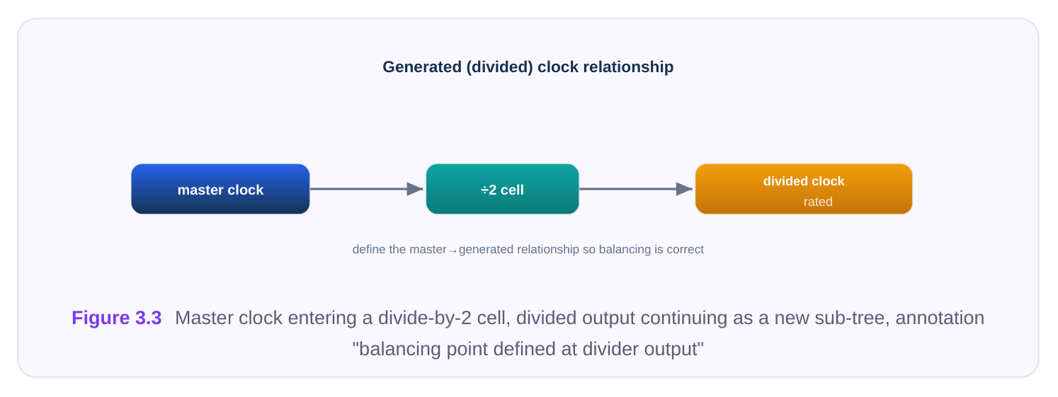
Why this must be specified rather than assumed: the insertion delay through the divider cell, plus any common upstream path, changes where "zero latency" should be measured. If the divided clock and the master both clock registers that exchange data, the spec must declare them balanced so the engine accounts for the divider's delay. If the divided clock feeds only its own isolated logic, declaring it independent frees the engine to optimize it separately. Getting this wrong produces a tree that meets its own skew target but fails inter-domain setup or hold timing — a failure that looks puzzling until you realize the balancing intent was misdefined.
The clock tree specification
The clock tree specification is the structured, machine-readable description of everything above. It is the contract between you and the engine. A well-formed spec answers, for every clock: where does it start, what should the tree achieve, what cells may be used, and what must the engine leave alone. Specs are typically expressed as a set of commands or a structured file, and most flows support per- clock overrides so that a global default can be tightened or relaxed for specific clocks. A good way to think about the spec is as a layered set of defaults and exceptions. At the top sits a global default that applies to every clock unless overridden — a baseline skew target, a default cell list, a default transition limit. Beneath that, per-clock blocks override the default where needed: a highspeed clock gets a tighter skew and a richer cell list; a low-activity configuration clock gets a relaxed target so the engine spends no effort it does not need to. At the bottom sit per-pin and per-group exceptions — the insertion delays, ignore declarations, and don't-touch protections. When the engine resolves what to do at a given pin, it reads from the most specific applicable rule outward. Writing a spec this way keeps it readable and makes the intent auditable: a reviewer can see at a glance which clocks deviate from the baseline and why. One discipline pays off repeatedly: keep the spec self-documenting. Comment each non-obvious override with the reason — "relaxed skew, no critical paths in this domain" — because six months later, neither you nor the next engineer will remember why one clock has a 120 ps target while everything else sits at 50 ps. The spec is read far more often than it is written. The core spec elements are summarized below.
| Spec element | Meaning | Why it matters |
|---|---|---|
| Clock root | The definition point where the tree begins | Anchors traversal; wrong root means wrong tree |
| Skew target | Maximum allowed skew within a group | Directly bounds the dominant uncertainty term in timing |
| Latency target | Desired insertion delay from root to sinks | Controls absolute arrival; key for inter-clock matching |
| Transition (slew) | Maximum allowed clock edge rate at | Guards against duty-cycle and reliability |
| target | sinks | degradation |
| Buffer/inverter cell | Cells the engine may instantiate list | Restricts the tree to characterized, balanced library cells |
| Don't-touch / don't- | Cells or nets the engine must not size | Protects pre-built or hand-crafted structures alter |
| Exclude / ignore | Topology boundaries and balancing | Defines what the tree reaches and what it |
| pins | exceptions | balances |
| Skew group | The set of endpoints balanced definition | Encodes balancing intent, not just delivery together |
| Inter-clock | Which clocks balance against which | Controls cross-domain relative latency |
relationship
Per-clock override Local change to any global default Lets one clock be stricter or looser than the
LATENCY TARGETS AND PIN INSERTION DELAYS
Two spec items deserve a closer look because they are frequently confused. A latency target is the insertion delay you want the engine to aim for from root to sinks. You might leave it free (let the engine minimize naturally) or pin it to a value so that this clock's depth matches another clock's depth — the foundation of inter-clock balancing. Targeting a specific latency rather than "as small as possible" is how you align two trees of different natural depths to a common reference. A pin insertion delay (sometimes called a per-pin offset or assertion) lets you tell the engine that a particular endpoint should be reached earlier or later than the group baseline. This is the mechanism behind intentional useful skew at the spec level: you assert that a critical capture flop should see the clock, say, 30 ps later, and the engine builds that offset into the tree rather than treating it as error to be removed. Distinguishing a target (a goal for the whole tree or group) from an insertion delay (a perpin adjustment) is a common interview discriminator.
Building a spec: generic command sketch
The following sketch shows how the elements above come together. The command names are generic stand-ins — every flow has its own spelling, but the structure is universal: define the root, set the targets, constrain the cells, declare the balancing groups, and record the exceptions.
# --- Define the clock root and its tree ---
create_clock_tree -name core_clk -root [get_pins pll/CLKOUT]
# --- Quality targets for this tree ---
set_clock_tree_target -tree core_clk \
-max_skew       50ps  \
-max_latency    900ps \
-max_transition 80ps
# --- Library cells the engine may use ---
set_clock_tree_cells -tree core_clk \
-buffers   {CLKBUF_X4 CLKBUF_X8 CLKBUF_X16} \
-inverters {CLKINV_X4 CLKINV_X8}
# --- Define the balancing set (skew group) ---
create_skew_group -name dp_group -tree core_clk \
-sinks [get_pins {dp_reg*/CK}]
# --- Exceptions: stop tracing, and deliver-but-don't-balance ---
set_clock_tree_exception -tree core_clk \
-exclude_pins [get_pins gate_cell/DIN] \
-ignore_pins  [get_pins legacy_blk/CLK]
# --- Protect a hand-built structure ---
set_clock_tree_dont_touch [get_cells preroute_buf_*]
A second sketch shows a generated clock and an inter-clock relationship — the part candidates most often omit.
# --- Divided clock: define its root at the divider output ---
create_clock_tree -name div2_clk -root [get_pins div_reg/Q] \
-generated_from core_clk
# --- Per-clock override: looser skew, this domain is non-critical ---
set_clock_tree_target -tree div2_clk -max_skew 90ps
# --- Balance the two clocks against each other at the crossing ---
set_interclock_balance -groups {dp_group div2_group} -mode balanced
# --- Per-pin offset: intentional useful skew on a critical capture flop ---
set_pin_insertion_delay [get_pins crit_capture_reg/CK] -delay 30ps
Read these two blocks together and you have, in miniature, the entire conceptual payload of this chapter: roots, targets, cell lists, skew groups, exceptions, generated-clock relationships, inter-clock balancing, and per-pin offsets.
Interview Q&A
exclude (stop) pin is a topology boundary: the engine stops tracing the clock there and builds no tree beyond it. An ignore pin is a balancing exception: the engine still delivers a buffered clock to that pin, but does not include it when computing or optimizing skew. Use exclude at structural edges (e.g., a gating cell's data input); use ignore for endpoints that need a clean signal but no latency matching, such as a self-contained block's clock input.
linked by a timing path. Endpoints in unrelated domains never launch/capture against each other, so balancing them wastes buffers and constrains the engine for no timing benefit — and can degrade the skew you actually needed. Some endpoints are also deliberately offset (useful skew, divided clocks), and lumping them together fights that intent. Groups are defined by connectivity and timing relationships, not physical location.
What likely went wrong in the spec? The clock-to-clock relationship was probably misdefined. The divided clock was likely treated as an independent root rather than being balanced against its master at the crossing, so the engine never accounted for the divider cell delay and the shared upstream path in the relative latency. The fix is to declare an inter-clock balancing relationship (or set matched latency targets) so the two trees share a common latency reference where data crosses.
a goal for the insertion delay of a whole tree or group — often pinned to a value to match another clock's depth for inter-clock balancing. A pin insertion delay is a per-pin adjustment that tells the engine to reach one specific endpoint earlier or later than its group baseline; it is the spec-level mechanism for intentional useful skew. One sets the tree's overall depth, the other applies a targeted offset to a single sink.
Key Takeaways
- A clock tree runs root → buffers/inverters → sinks; the engine owns everything in between but must be told how to treat each endpoint.
- Ignore = deliver but don't balance; exclude = don't even trace past here. These are different kinds of exceptions.
- A skew group is the set of endpoints balanced relative to each other; skew is only meaningful within a group, and groups are defined by timing/connectivity, not proximity.
- Inter-clock balancing controls relative latency where domains exchange data; the engine cannot always infer these relationships, so the spec must declare them.
- Generated/divided clocks need explicit clock-to-clock relationships so the divider delay and shared upstream path are correctly accounted for.
- The clock tree spec is the contract with the engine: roots, skew/latency/transition targets, cell lists, exceptions, skew groups, inter-clock relationships, and per-clock overrides.
- Distinguish a latency target (whole-tree/group goal) from a pin insertion delay (per-pin offset for intentional useful skew).
Comments
Leave a Reply