 ChipBuddy
← Home
ChipBuddy
← Home
Pin Insertion Delays & Skew Groups
Clock tree synthesis spends most of its effort answering a single question for every sink: when does the clock edge need to arrive here? For an ordinary flip-flop the answer is simple — the edge should arrive at the same logical instant as it does at every other balanced flop. But real designs are full of sinks that are not ordinary. A hard macro buries its own clock network inside an opaque boundary. An integrated memory adds picoseconds of internal latency before the edge reaches its capture element. A clock-gating cell sits on a boundary between the part of the tree the engine builds and the part it inherits. If you let the engine treat these endpoints as if they were plain flops, it will balance to the wrong point in space and time, and the resulting skew will be invisible in CTS reports yet very real in static timing. This chapter is about telling the truth to the engine. Pin insertion delays declare hidden latency that the tool cannot see. Skew groups declare which endpoints should be balanced against each other and which should not. Together they convert a naive "balance everything to zero" tree into a structured, intentional one.
What a Pin Insertion Delay Actually Means
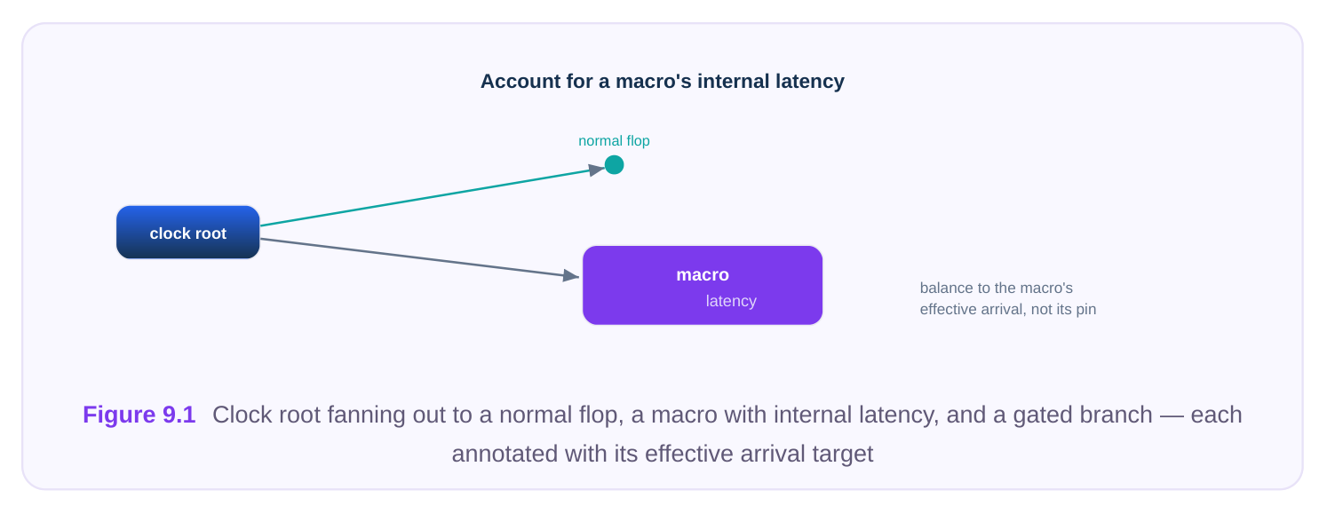
A pin insertion delay (also called a sink insertion delay or pin latency) is an annotation on a clock sink that says: the clock edge does not capture data at this physical pin — it captures somewhere downstream of it, after an additional fixed delay that I am telling you about. The engine then balances so that the effective arrival (network latency to the pin plus the declared insertion delay) lines up with the rest of the group, rather than balancing the pin itself. The classic example is a hard macro. Suppose a memory has 300 ps of internal clock latency between its external clock pin and the internal capture register. The flops in your block see the clock through the synthesized tree only. If the engine balances the macro's pin to the same arrival as those flops, then the macro's capture point arrives 300 ps late, and you have built 300 ps of skew on purpose. The fix is to declare a 300 ps insertion delay on the macro pin so the engine drives the tree to that pin 300 ps early, cancelling the hidden latency. The same logic applies at clock-gating boundaries, at the interface to a pre-built or hardened subblock, and at any pin where downstream latency exists but is not part of the network the current CTS run controls.
| Situation | Why an insertion delay is needed |
|---|---|
| Hard macro / IP with internal clock | The capture element sits behind opaque internal latency; balancing the |
| network | visible pin mistimes the real flop |
| Compiled memory (RAM/ROM) | Internal clock buffering adds fixed delay before the array is clocked |
| Hardened sub-block delivered with | The block's internal tree is fixed; the parent must balance to the block's |
| its own CTS | effective arrival, not its top pin |
| Clock-gating boundary handed off | Downstream insertion delay belongs to a tree built in another step or |
| between flows | another partition |
| Analog / mixed-signal clock input | Receiver has a characterized internal delay that timing must account |
for
Off-chip or feedthrough sink Real latency lives outside the netlist the engine can traverse The number you declare should come from the cell's timing model or the sub-block's signoff data — never a guess. Many models already carry the latency as an arc inside the library description; in that case the engine may read it automatically, and you only annotate manually where the model is silent or where you are abstracting a block.
How a Wrong or Missing Insertion Delay Corrupts Balancing
Because balancing is a comparison of arrival times, a single bad insertion delay does not just mistime one sink — it shifts the reference everything else is measured against, so error can propagate. Consider a group containing many flops and one memory. If the memory truly has 300 ps of internal latency but you declare zero (or forget to declare it), the engine balances the memory pin to the same arrival as the flops. The memory's internal register now captures 300 ps late. Worst case, the engine also uses the memory as a balancing reference and over-buffers the flop branches to "match" it, dragging the whole group's latency up and burning power for negative benefit. The opposite error is just as damaging. Declare 300 ps when the real value is 100 ps and the engine drives the pin 200 ps too early. The memory now captures early, eating into hold margin on its data paths and possibly opening a setup violation on the launch side.
Insertion-delay
Effect on the tree Timing symptom
| Missing (declared 0, | Pin balanced too late; engine may | Skew at the true capture point; setup |
|---|---|---|
| real > 0) | over-buffer peers to match | failures downstream of the sink |
| Under-declared | Pin still arrives late relative to peers | Residual skew, setup risk on paths into the |
sink
| Over-declared | Pin driven too early | Hold risk into the sink; early-mode failures |
|---|---|---|
| Applied to wrong pin | A normal sink mis-balanced | Localized skew that CTS reports as "clean" |
The dangerous part is that CTS skew reports look fine. The engine reports skew at the pins it balanced, and it balanced them exactly as told. The error only surfaces in full static timing analysis, where the library arc through the macro is honoured. This is why insertion-delay review is a sign-offquality task, not a cosmetic one. There is a second-order trap worth naming explicitly. Insertion delays interact with the engine's latency targeting. Many flows let you ask for an overall target insertion delay (the latency the whole tree should aim for). If one sink declares a large pin insertion delay, the engine must drive that branch much earlier than the rest, which can push the minimum achievable network latency up for the whole group — every other sink has to be slowed down to keep skew tight relative to the early-driven one. A single 500 ps macro latency in a group targeting 200 ps of network latency is therefore not free: it can inflate global latency, transition counts, and dynamic power. When you see latency targets that refuse to converge, audit the insertion delays first; an outlier value is a common root cause.
SOURCE AND SINK LATENCY ARE NOT THE SAME THING
A frequent point of confusion in interviews and in practice is mixing up source latency with pin insertion delay. Source latency models the network upstream of the clock definition point — for example, the delay from an off-chip oscillator or a PLL output to the clock port the engine considers its root. Pin insertion delay models latency downstream of a sink pin the engine cannot traverse. Source latency shifts the whole tree's reference; pin insertion delay shifts one endpoint's effective arrival. Confusing the two leads to double-counting (applying the same physical delay in two places) or to a phantom skew that no amount of buffering will close. Keep a clear mental model: source latency = before the root, network latency = what CTS builds, insertion delay = hidden tail after a sink.
# Declare hidden latency at sinks the engine cannot see through.
# Effective arrival = network latency to pin + declared insertion delay.
set_clock_pin_insertion_delay -clock CLK -delay 0.300 [get_pins u_mem0/CK]
# Apply the same value to a family of identical instances.
foreach m [get_cells -hier -filter "ref_name =~ SRAM_*"] {
set_clock_pin_insertion_delay -clock CLK -delay 0.300 [get_pins $m/CK]
}
# Abstract a hardened sub-block: balance to its effective arrival,
# not to its top-level clock port.
set_clock_pin_insertion_delay -clock CLK -delay 0.180 [get_pins u_core/clk_in]
Skew Groups Revisited: Choosing Who Balances Against Whom
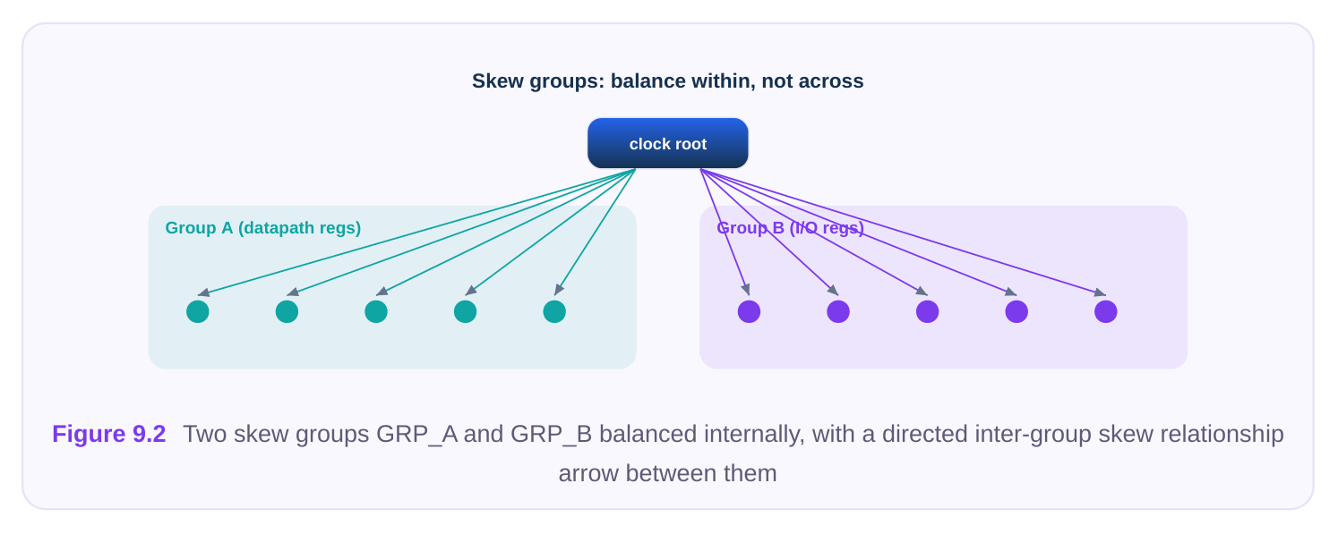
Earlier chapters introduced skew groups as a way to scope balancing. Here we look at them as the primary instrument for controlling it. A skew group is a named set of endpoints that the engine balances together — it works to equalize their effective arrivals. Just as important is what a skew group implies by exclusion: endpoints in different groups are not balanced against each other unless you declare an explicit inter-group relationship. Why split endpoints into groups at all? Because forcing unrelated endpoints to share an arrival wastes buffers and harms timing. Consider:
- A block with a launch domain and a capture domain that never form a register-to-register path together. Balancing them to each other achieves nothing and costs latency.
- Generated clocks (divided, gated) whose natural latency differs from the parent. Lumping them with the parent flops forces awkward compensation.
- Two physically distant regions where tight inter-region skew is unnecessary. Local balancing in each region is cheaper and good enough. The art is matching group boundaries to the timing relationships that actually exist. Endpoints that talk to each other in setup/hold paths must end up in the same (or an explicitly related) group; endpoints that never interact can live apart.
WAYS TO DEFINE SKEW-GROUP MEMBERSHIP
| Definition method | How membership is decided | Typical use |
|---|---|---|
| Explicit list | You name the endpoint pins or instances | Small, deliberate groups; macro-only |
groups
| Connectivity-based | All sinks reachable from a given clock/ | Per-clock or per-generated-clock |
|---|---|---|
| branch | grouping | |
| Timing-based | Endpoints that share real register-to- | Letting interacting flops self-select |
register paths
Hierarchy / region- Sinks within a module or floorplan region Local balancing of distant blocks
| Attribute / pattern- | Filter on name, ref, or user property | Bucketing similar IP (e.g. all |
|---|---|---|
| based | memories) |
Connectivity-based grouping is the common default: every sink fed by a clock becomes one group, and generated clocks form their own. Timing-based grouping is more refined — it lets the engine balance only the endpoints that genuinely share paths, which can relax over-constrained trees. Explicit lists are reserved for cases where you must override the automatic logic, such as isolating a set of source-synchronous output flops.
INTER-GROUP (CROSS-CLOCK) BALANCING RELATIONSHIPS
Separating endpoints into groups removes balancing between them — but sometimes a controlled relationship across the boundary is exactly what you need. Two domains that exchange data through a small number of synchronous paths may need their effective arrivals related, even if you do not want full mutual balancing. An inter-group skew relationship lets you state, for a pair of groups, either that their arrivals should be balanced to each other (treat as one for balancing) or that a specific offset should be held between them. The offset case is powerful: if domain B should naturally lead domain A by 150 ps to optimize a critical interface, you can declare that target rather than fighting it with manual buffering. This is the structural cousin of the useful-skew ideas covered with CCD elsewhere in this handbook — here it is expressed at the group level instead of the individual register level. There is also the question of direction. A balanced relation is symmetric: the engine tries to equalize the two groups' arrivals with no preference. An offset relation is directional — "from A to B, hold +150 ps" is not the same as "from B to A, hold +150 ps." Get the sign right by reasoning about the data path: the group that launches and the group that captures determine whether you want the capture clock early (helps setup, hurts hold) or late (the reverse). Declaring an offset is, in effect, baking a deliberate useful-skew decision into the tree structure, so it should be justified by the actual critical path and rechecked if the floorplan or the constraints change.
A WORKED REASONING EXAMPLE
Imagine a block with three populations of endpoints: the core logic flops (the bulk), a bank of two memories, and a small set of output registers that drive a source-synchronous interface off-block. A naive single-group tree would balance all three to one arrival. That is wrong on two counts. First, the memories carry internal latency that must be cancelled with insertion delays or they will capture late. Second, the output registers should arguably lead the core slightly so the launched data and its forwarded clock leave the block with the right relationship — a useful-skew goal, not a zero-skew one. The correct structure is three skew groups: core and memories balanced together (with the memory pins carrying their declared insertion delays so their effective arrivals match the core), and the output group held at a small declared offset relative to the core. This single example exercises every idea in the chapter — insertion delays, group partitioning, and inter-group offsets working together.
# Connectivity-based group: every sink of the main clock.
create_clock_skew_group -name GRP_CORE -clock CLK
# Explicit group: isolate source-synchronous output flops.
create_clock_skew_group -name GRP_IO_OUT \
-members [get_cells {u_phy/oddr_*}]
# Generated/divided clock gets its own group.
create_clock_skew_group -name GRP_DIV2 -clock CLK_DIV2
# Relate two groups: hold a 0.150 ns offset (B leads A) across the interface.
set_inter_skew_group_relation \
-from GRP_CORE -to GRP_IO_OUT -offset 0.150
# Or fully balance two interacting groups as if they were one.
set_inter_skew_group_relation -from GRP_CORE -to GRP_DIV2 -balanced true
Putting Insertion Delays and Groups in the Spec
In a spec-driven flow, insertion delays and skew-group membership live in the CTS specification file alongside target skew, transition limits, and buffer lists. Keeping them in the spec — rather than scattered through interactive commands — makes the intent reviewable, version-controllable, and reproducible across runs. A clean spec typically declares, per clock: the sink set, any per-pin insertion delays, the skew-group partition, and any inter-group relations. The engine reads this once and balances accordingly.
# ---- CTS specification excerpt ----
clock CLK {
target_skew     0.040
max_transition  0.120
# Hidden latencies the engine must honour.
pin_insertion_delay u_mem0/CK   0.300
pin_insertion_delay u_mem1/CK   0.300
pin_insertion_delay u_core/clk_in 0.180
# Partition endpoints into balancing groups.
skew_group GRP_CORE   { connectivity CLK exclude {u_phy/oddr_*} }
skew_group GRP_IO_OUT { members {u_phy/oddr_*} }
# Cross-group intent.
inter_group GRP_CORE GRP_IO_OUT { offset 0.150 }
}
A practical discipline: derive insertion-delay numbers from a single source of truth (the IP timing data or sub-block hand-off file) and generate the spec lines programmatically. Hand-typed latency values drift out of date the moment an IP is re-characterized, and a stale insertion delay is one of the hardest CTS bugs to spot.
Reporting: Per-Group Skew and Insertion-Delay Distribution
You cannot trust what you do not measure. After CTS, two reports matter most for this chapter's topics. First, per-skew-group skew: for each group, the minimum and maximum effective arrival, the resulting skew, and the worst sink pair. A group whose skew exceeds its target points to a balancing problem — often a missing buffer level or, tellingly, a forgotten insertion delay. Second, the insertion- delay distribution: a listing of every declared pin latency so a reviewer can confirm each one against the source data and catch the value that is zero when it should not be.
| Report | What it shows | What a problem looks like |
|---|---|---|
| Per-group skew | Min/max effective arrival and summary | A group over target while pins report "balanced" skew per group |
| Insertion-delay | Every declared sink latency and | A macro pin with 0 ns, or a value that disagrees |
| listing | its source | with the IP datasheet |
| Cross-group offset | Achieved vs. requested inter- check | Offset not met — interface paths at risk group offset |
| Effective-arrival | Spread of arrivals within a group histogram | Bimodal spread hinting at two un-related sub- populations |
# Skew per group, with the worst contributing pin pair.
report_clock_skew -group_by skew_group -show_worst_pair
# Audit every declared insertion delay against its annotation.
report_clock_pin_insertion_delay -all -show_source
# Confirm cross-group offsets were actually achieved.
report_inter_skew_group_relation -achieved
Read these reports before full static timing, but always confirm in STA, where the library arcs through macros are honoured and the truth of your insertion delays is finally tested.
Interview Q&A
report, and what breaks? CTS reports clean skew — it balanced the memory's external pin to the same arrival as the flops, exactly as it understood the problem. Nothing looks wrong in the CTS summary. The breakage appears in static timing: the memory's internal capture register now sees the edge 250 ps late, creating real skew on every path into and out of the memory and likely producing setup violations on paths feeding it. The lesson is that CTS skew reports measure balanced pins, not true capture points.
groups when the domains share few or no synchronous register-to-register paths — balancing them to each other would burn buffers and add latency for no timing benefit. Use one group (or an explicit inter-group balanced relation) when the domains exchange data on paths that must meet setup and hold, so their effective arrivals need to track each other. The deciding factor is the timing relationship that actually exists between endpoints, not their names or proximity.
domain? An inter-group offset is a declared balancing target between two groups — the engine actively works to hold that arrival difference and reports whether it achieved it. Abusing an insertion delay to shift a whole domain is a hack: it mis-states hidden latency, corrupts the effective-arrival math for every sink involved, and produces misleading reports. The offset expresses intent cleanly and is honoured by both CTS and downstream analysis; the insertion-delay hack hides intent and creates a value that will eventually be wrong.
pin gets driven too early, so its capture element clocks ahead of its peers. The symptom is hold-time / early-mode risk on paths into that sink — the data may not be stable when the early edge arrives. It is caught in hold (minimum-delay) static timing analysis, and on the achieved-skew report for the affected group if you compare to the true library latency. Setup mode may look fine, which is why hold sign-off must be run against the real macro models, not the CTS view.
Key Takeaways
- A pin insertion delay declares hidden downstream latency so the engine balances to the effective arrival (network latency + declared delay), not to the visible pin.
- Hard macros, compiled memories, hardened sub-blocks, and clock-gating boundaries almost always need insertion delays; source the numbers from IP/sub-block sign-off data, never guesswork.
- A missing or wrong insertion delay produces skew that CTS reports as clean but that fails in static timing — under-declaring risks setup, over-declaring risks hold.
- Skew groups control who balances against whom; matching group boundaries to real register-to- register timing relationships avoids wasting buffers on unrelated endpoints.
- Define membership by connectivity, timing, hierarchy/region, or explicit list — and use inter-group relations to balance or hold a deliberate offset between interacting domains.
- Keep insertion delays and group definitions in the version-controlled spec, generate latency values from a single source of truth, and verify with per-group skew and insertion-delay reports before confirming in full STA.
Comments
Leave a Reply