 ChipBuddy
← Home
ChipBuddy
← Home
Prerequisites & Design-State Requirements
Clock Tree Synthesis does not happen in a vacuum. Before a tool can ever start dropping clock buffers and balancing skew, the design has to be coaxed into a very specific state. Think of CTS as a highprecision manufacturing step: the raw material (your placed netlist), the machine settings (your constraints and scenarios), and the supporting infrastructure (power delivery) all have to be correct before you press "go." Skip any of these prerequisites and you will either get a tool error, or worse, a clock tree that looks fine in the log but falls apart at signoff. This topic walks through every condition the design must satisfy before CTS, why each one matters physically, and how engineers verify readiness in practice. Getting these prerequisites right is one of the most common things interviewers probe, because it separates someone who has only read about CTS from someone who has actually pushed a block through it.
2.1 Clock Sources Must Be Defined
The single most fundamental prerequisite is that the tool must know what a "clock" actually is in your design. CTS operates on clock networks, and a clock network only exists if a timing constraint declares it. If you launch CTS without defined clocks, the tool has nothing to synthesize a tree for, the sinks are invisible, and you get either an empty result or an outright error. Clocks enter the design through a handful of well-defined mechanisms, and a real chip almost always uses several of them at once.
Primary input clocks via create_clock
The cleanest case is a clock that arrives at a top-level port from outside the block. You define it with
create_clock , attaching a waveform (period and duty cycle) to a pin or port. This becomes a masterclock: an independent timing reference that the rest of the clock structure is derived from.
# Define a 1 GHz primary clock on the top-level port CLK_IN
create_clock -name SYS_CLK -period 0.96 -waveform {0 0.5} [get_ports CLK_IN]
# A second asynchronous reference clock at 100 MHz
create_clock -name REF_CLK -period 9.6 [get_ports REF_CLK_IN]
The period drives everything downstream: setup checks, the skew budget, and the insertion-delay targets the tool will try to honor. A missing or wrong period here corrupts the entire CTS run.
Generated clocks via create_generated_clock
Most real designs do not run every flop off the raw input clock. Dividers, multiplexers, and clockshaping logic produce derived clocks whose timing is mathematically related to a master. These are described with create_generated_clock , which tells the tool "this clock is the parent clock, transformed by this rule."
# A divide-by-2 clock generated at the output of a divider flop
create_generated_clock -name DIV2_CLK \
-source [get_pins clk_div_reg/CK] \
-divide_by 2 \
[get_pins clk_div_reg/Q]
Generated clocks matter enormously for CTS because the tool must build and balance the tree up to and through these generation points. If a generated clock is undefined, the flops it drives appear to belong to the parent clock (or to nothing), the balancing math is wrong, and you can ship a block with hidden skew between a clock and its own divided version.
PLL output clocks
On-chip PLLs are the workhorse for clock generation, multiplying a slow reference up to the operating frequency. The PLL output is conceptually a master clock, but it is created inside the block rather than arriving at a port. The standard practice is to place a create_generated_clock (or, depending on flow and PLL model, a create_clock ) on the PLL output pin, referencing the input reference clock and the multiplication factor.
# Reference into the PLL
create_clock -name PLL_REF -period 19.0 [get_ports PLL_REF_IN]
# PLL multiplies the 50 MHz reference up to 1 GHz (x20) at its output
create_generated_clock -name PLL_OUT \
-source [get_pins pll_inst/REF] \
-multiply_by 20 \
[get_pins pll_inst/CLKOUT]
A practical subtlety: the PLL itself is typically a hard macro that you do not want CTS to route through or insert buffers inside. The clock tree begins at the PLL output pin and fans out from there. You will usually mark the PLL output as the tree root and treat the macro as a black box.
Gated clocks
Clock gating is the dominant dynamic-power technique in modern SoCs, so virtually every block has integrated clock-gating cells (ICGs) sitting in the clock path. CTS must understand and preserve these gates: it has to build the tree through the ICG, balance the legs on both sides, and respect the gate's enable timing. As long as the upstream clock is properly defined, the tool propagates clocks through the ICG automatically, but you must make sure the gating cells are real ICG cells from the library (not random AND gates the tool will try to "optimize") and that their enable paths are constrained.
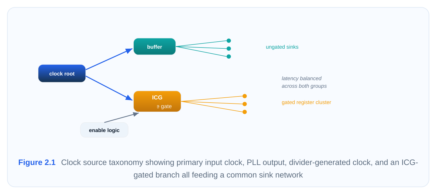
The table below summarizes the source types and how they are declared.
Clock source
Declaration Role in CTS
| Primary input | create_clock on a port | Master reference; sets period and skew |
|---|---|---|
| clock | budget | |
| Divided / derived | create_generated_clock -divide_by clock | Tree must balance through generation point |
| PLL output | create_generated_clock -multiply_by on PLL pin | Tree root inside the block; macro is a black box |
| Gated clock | Inherited through ICG cell | Tree built through the gate; enable |
timing preserved
2.2 Design Must Be Placed and Optimized
CTS is a physical step. It computes wirelength, estimates RC delay, and decides where to drop buffers based on the actual coordinates of the sinks it has to reach. None of that is possible if the cells have no locations. Therefore the design must be fully placed, and that placement must be both legal and reasonably optimized, before CTS begins.
place_design
Placement assigns an (x, y) location to every standard cell and fixes the positions of macros. After place_design , the tool knows where every flip-flop, latch, and ICG lives, which means it can finally estimate the distances the clock has to travel and the loads it has to drive.
# Run global + detailed placement
place_design
# Pull a quick report to sanity-check density and overflow before moving on
report_placement -congestion
A useful mental model: placement defines the geography of the clock problem. The sinks are scattered cities; CTS is the highway-and-distribution network that has to reach all of them with matched arrival times. Move the cities (re-place after CTS) and the highways no longer line up, which is exactly why you do placement first and lock it down.
Legality via check_legality
A placement is legal when every cell sits on a valid row and site, snapped to the placement grid, with no overlaps and all design rules respected. CTS assumes legality. If cells overlap or sit off-grid, the buffer-insertion and routing estimates become garbage, and detailed routing later will fail.
# Verify the placement is DRC-clean and overlap-free
check_legality
# If issues are reported, run incremental legalization
legalize_placement
Run the legality check explicitly before CTS rather than assuming the placer left things clean, especially after any manual ECO moves.
Placement optimization
Raw placement is not enough; the design also needs to have been optimized. Pre-CTS optimization (often called placement optimization or "place_opt") fixes timing as best it can under an ideal-clock assumption, sizes cells, restructures logic, and inserts buffers on long data paths. Why does this matter for CTS? Because CTS inserts a real clock tree with real insertion delay, and that interacts with data-path timing. If the data paths are a mess going in, the post-CTS picture is hopeless. You want the design to be in good shape under ideal clocks so that when the clock becomes "propagated," the only new problems are the ones CTS itself introduces.
Handling illegal placements
If check_legality flags problems, do not proceed. Common fixes, in escalating order:
- 1. Incremental legalization to snap and de-overlap cells with minimal disturbance.
- 2. Targeted manual moves for a handful of stubborn cells, then re-legalize.
- 3. Re-running placement with adjusted density targets or padding if the violations are widespread,
which usually signals a congestion or floorplan problem rather than a local glitch. The key discipline is that you never "push through" an illegal placement into CTS hoping it sorts itself out. It will not.
2.3 Quality of Results Must Be Acceptable
Even a legal, placed, optimized design can be a poor candidate for CTS if its quality of results (QoR) is bad. CTS will add buffers, wires, and routing demand on top of whatever is already there. If the design is already congested or already failing basic electrical limits, CTS makes it worse, not better. The rule of thumb is simple: clean up the QoR before CTS, because CTS is not a repair step for placementstage problems.
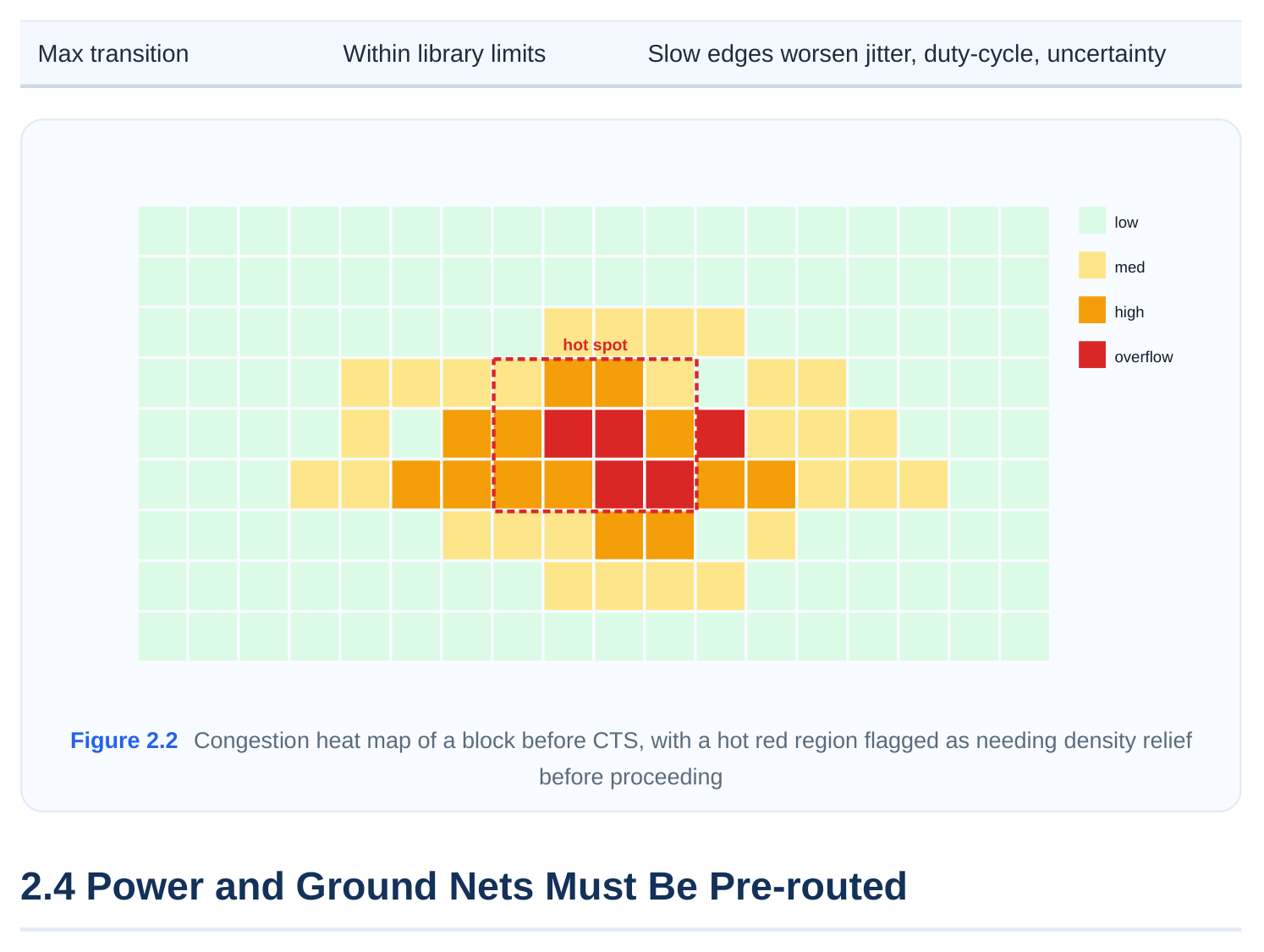
Congestion below ~68%
Routing congestion is measured as the ratio of demanded routing tracks to available tracks in each region (GCell). A widely used guideline is to keep overflow such that utilization of routing resources stays under roughly 68% in the worst regions before CTS. The reason is direct: CTS injects a substan‐
tial number of new clock nets and buffers, all of which need routing tracks. If you are already near saturation, adding the clock network tips the design into unroutable congestion, and you discover it only at the routing stage when fixing it is expensive. If congestion is too high, address it at the placement/floorplan level: spread cells, add placement blockages or padding around hot spots, adjust macro placement, or reduce density. Do this before CTS.
Timing acceptability
The pre-CTS timing picture is computed with an ideal clock (zero skew, zero insertion delay). That is optimistic by design. CTS will replace that ideal clock with a real, propagated one, which adds insertion delay and a small amount of real skew, generally eroding setup margin somewhat while helping or hurting hold depending on path structure. For this to end well, the pre-CTS timing must already be acceptable with healthy margin, so the design can absorb the degradation CTS introduces. A design that barely meets timing under an ideal clock will almost certainly fail once the clock becomes real.
Max capacitance feasibility
Every cell output has a maximum capacitive load it can legally drive ( max_capacitance ), defined by the library. Before CTS you should confirm there are no rampant max-cap violations on data paths, and crucially that the clock sources and any pre-existing clock-path cells can drive what is being asked of them. CTS will create its own buffer tree that respects max-cap on the clock nets, but if the surrounding design is already drowning in max-cap problems, those are signals of under-sized drivers or excessive fanout that should be cleaned up first.
Max transition feasibility
Closely related is max_transition , the limit on how slowly a signal's edge is allowed to rise or fall. Slow transitions on clock-related pins are especially dangerous: they increase delay uncertainty, degrade duty cycle, and inflate jitter sensitivity. Before CTS, the existing transitions should be within limits so that CTS starts from a clean electrical baseline. The clock tree itself will be built to tight transition targets, but feeding it from a source that already has a sluggish edge undermines the whole exercise.
| QoR metric | Pre-CTS target | Why CTS cares |
|---|---|---|
| Routing congestion | < ~68% peak utilization | CTS adds many new nets; no headroom = unrout‐ |
able
Setup timing (ideal Met with positive margin CTS adds insertion delay; margin gets eaten
Max capacitance No widespread viola‐ Indicates under-sized drivers / excess fanout
Clock buffers are among the most active, highest-switching cells on the entire die. They toggle every single cycle, they are large, and there are thousands of them. All of that switching draws current, and that current has to come from a stable supply. This is why the power delivery network (PDN) must be built and routed before CTS, not after.
VDD/VSS power straps
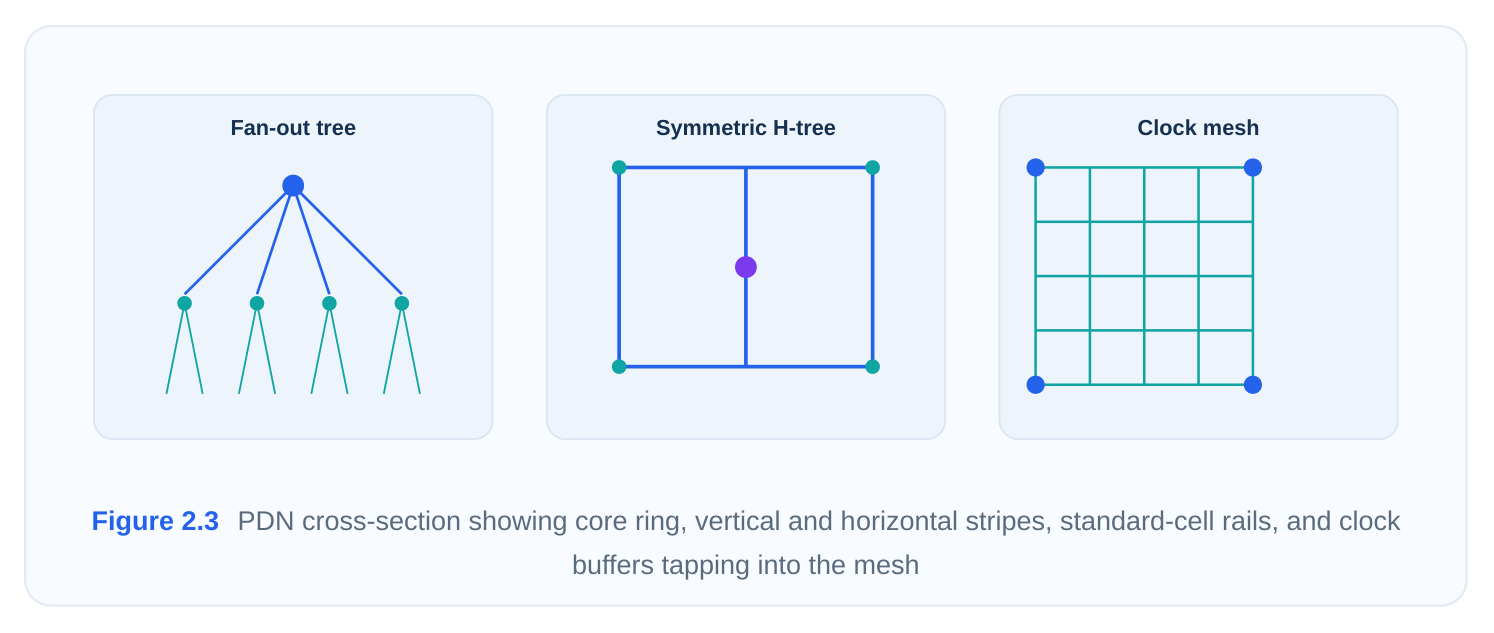
The PDN consists of a hierarchy: the standard-cell power rails in each row, vertical and horizontal straps (also called stripes) on the upper metal layers, and a ring around the block or around macros that ties the whole thing together. These connect down to the package and ultimately to the off-chip supply. Pre-routing means this entire mesh is laid out and connected before CTS runs.
Stable supply for clock buffers
Here is the physical heart of the requirement. When a clock buffer switches, it pulls a current spike from VDD and dumps charge into VSS. If the local supply sags during that spike (IR drop), the buffer's delay increases. Now imagine that happening unevenly across the die: buffers in a weak-supply region are slower than buffers in a strong-supply region, and you have just created skew that did not exist in your nominal timing model. Worse, supply noise translates directly into clock jitter. A clock tree balanced on top of a noisy or sagging supply is a clock tree that does not actually meet the skew it claims. So the PDN must be in place first for two reasons:
- 1. CTS needs to know where the power structures are so it can place buffers in legal, powered
locations and route clock nets around the straps.
- 2. The supply must be robust enough that the inserted buffers see a stable VDD, otherwise the
carefully balanced tree is undermined by IR-drop-induced skew and jitter.
Stripes and rings
Practically, you ensure adequate strap density and ring strength before CTS, then verify with an early IR-drop / EM analysis if the flow supports it. If the PDN is too sparse, the right fix is to add stripes or widen the mesh now, while the clock tree has not yet been built around it. Rebuilding the PDN after CTS forces a re-do of the clock tree, so this ordering is deliberate.
2.5 Active Scenarios Must Be Defined
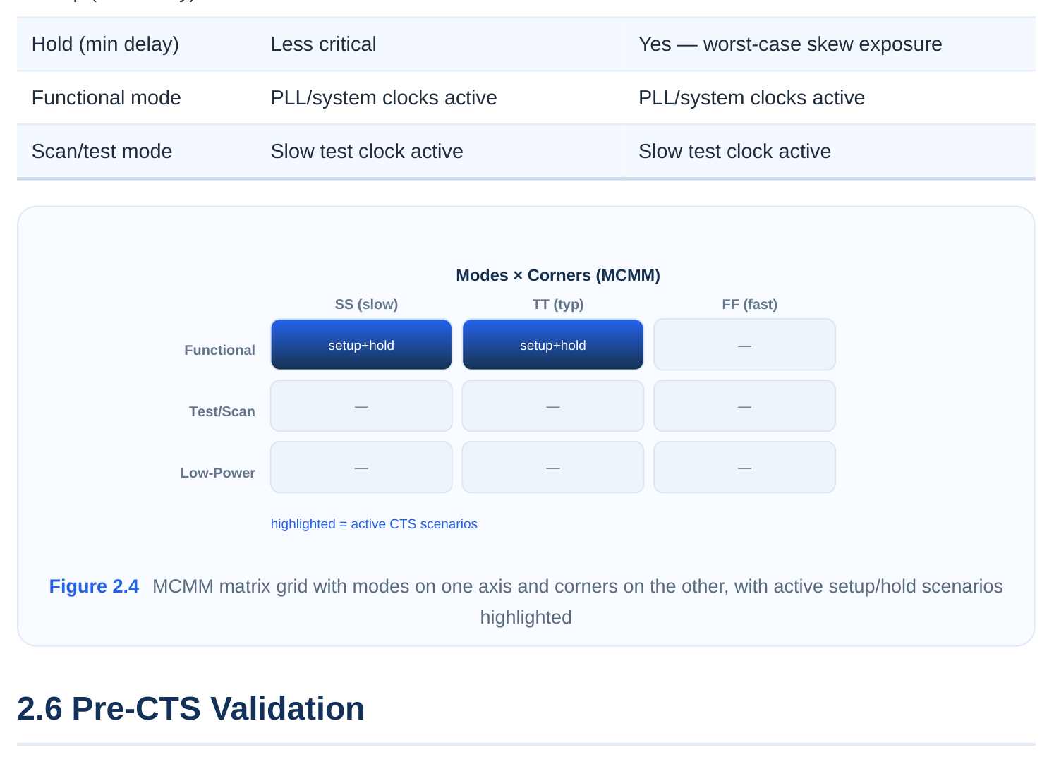
A modern chip does not have one timing condition; it has many. It runs in different functional and test modes, it must be verified across multiple PVT corners (process, voltage, temperature), and it has distinct setup and hold requirements. CTS in a modern flow is multi-corner multi-mode (MCMM) aware: it balances the clock tree while honoring all the active analysis views simultaneously. For that
to work, every scenario you intend to optimize and check against must be defined and activated before CTS.
Setup scenarios
Setup (max-delay) analysis is worst-case at the slow conditions: slow process, low voltage, the tem‐ perature that maximizes delay for your technology. CTS uses setup scenarios to make sure that, after insertion delay is added, capture flops still get their data in time. You typically define a setup view per relevant mode at the slow corner.
Hold scenarios
Hold (min-delay) analysis is worst-case at the fast conditions: fast process, high voltage. Hold is acutely sensitive to clock skew, which is precisely what CTS controls. If hold scenarios are not active during CTS, the tool can balance for setup in a way that creates hold problems that only surface later. Defining hold scenarios up front lets CTS keep skew within bounds that both setup and hold can live with.
Modes
A mode captures a self-consistent set of constraints, an SDC describing how the chip is configured: functional mode, scan-shift mode, scan-capture mode, low-power/retention mode, and so on. Each mode can have different active clocks (scan mode often uses a slow test clock; functional mode uses the PLL output). CTS must build a single physical tree that works across all active modes, so each mode must be declared.
PVT corner configurations
A corner is a set of physical conditions: a process model (slow/typical/fast), a supply voltage, and a temperature, paired with the matching parasitic-extraction (RC) corner. A scenario (or analysis view) in MCMM is the cross-product of a mode and a corner, with a constraint type (setup or hold). You enable exactly the scenarios that matter for CTS, balancing thoroughness against runtime.
# Define corners (library + RC condition)
create_corner slow
create_corner fast
# Define modes (each points at an SDC)
create_mode -name func  -constraint_file func.sdc
create_mode -name scan  -constraint_file scan.sdc
# Build scenarios as mode x corner x check, and activate them for CTS
create_scenario -name func_setup -mode func -corner slow
create_scenario -name func_hold  -mode func -corner fast
create_scenario -name scan_setup -mode scan -corner slow
set_active_scenarios {func_setup func_hold scan_setup}
The exact commands vary by tool, but the concept is universal: tell the tool which mode/corner/check combinations are live, and CTS optimizes to satisfy all of them at once.
| Scenario element | Slow corner emphasis | Fast corner emphasis |
|---|---|---|
| Setup (max delay) | Yes — worst-case data arrival | Less critical |
Everything above culminates in a validation gate. Before committing to CTS, an experienced engineer runs a deliberate checklist to confirm the design is genuinely ready, because a CTS run can take hours and a preventable input error wastes all of it. Pre-CTS validation has four pillars.
Clock definition verification
Confirm that every clock the design needs is defined and reaching the right pins. Use the timing tool's clock reporting to enumerate master and generated clocks, then verify that propagation actually reaches the leaf flops you expect.
# List all clocks the tool currently knows about
report_clocks
# Verify clock propagation reaches the expected sinks
report_clock_tree -summary
# Confirm there are no unconstrained or unclocked registers
check_timing -include {unconstrained_endpoints no_clock}
Two classic failures to hunt for: registers with no clock (CTS will ignore them, and they show up as tim‐ ing holes later) and clocks that are defined but not propagated to where you assumed.
Design legality checks
Re-confirm placement legality and that no DRC-affecting changes slipped in since placement. This is the check_legality step from 2.2, repeated as a gate immediately before CTS so that any late ECO moves are caught.
Constraint feasibility
Verify that the constraints are not just present but achievable. This means checking for clock defini‐ tions that conflict (overlapping generated clocks, contradictory waveforms), missing clock-group relationships between asynchronous clocks, and SDC errors. A common technique is to run a constraint linter or the tool's check_timing with a broad set of checks and read the report end to end. Infeasible constraints, for example a skew target tighter than the technology can deliver, will quietly cause CTS to spin or produce a poor tree.
Scenario validation
Confirm that the intended MCMM scenarios are actually active and that each one has valid libraries, a valid SDC, and a valid RC corner attached. A frequent and embarrassing bug is running CTS with only the setup scenario active, then discovering massive hold violations at signoff because the hold scenario was defined but never set active. Validate that the active-scenario list matches your intent.
# Report which scenarios are active and what they contain
report_scenarios
# Broad pre-CTS timing/constraint sanity check across active views
check_timing -verbose
A consolidated pre-CTS checklist, the kind worth memorizing for an interview:
| Check | Question it answers | Tool action |
|---|---|---|
| Clocks defined | Does every clock exist and propagate? | report_clocks , report_clock_tree |
| Placement legal | Are all cells on-grid, no overlaps? | check_legality |
| Congestion OK | Is there routing headroom for clock nets? | report_congestion |
| Timing healthy | Is there margin to absorb insertion delay? | report_timing |
| Max cap / trans | Are electrical limits respected? | report_constraint |
| PDN routed | Is the supply stable for clock buffers? | PDN / IR-drop report |
| Scenarios active | Are all setup/hold/modes/corners live? | report_scenarios |
When all seven of these pass, the design is genuinely CTS-ready, and the run that follows has a real chance of producing a balanced, low-skew, signoff-clean clock tree on the first attempt.
Interview Q&A
Clock buffers switch every cycle and draw large, repetitive current spikes. If the PDN is weak or absent, those spikes cause IR drop that increases buffer delay non-uniformly across the die, which manufactures skew that your timing model does not predict, plus supply noise that becomes clock jitter. CTS also needs to know where the straps are to place buffers in legal, powered sites and route clock nets around the mesh. Building the PDN afterward would force the entire clock tree to be rebuilt, so the ordering is deliberate.
care? A master clock is an independent reference defined with create_clock , carrying its own waveform. A generated clock, defined with create_generated_clock , is derived from a master by a known trans‐ formation (divide, multiply, phase shift) and lives at the output of generation logic like a divider or PLL. CTS cares because it must build and balance the tree all the way through the generation point. If a generated clock is undefined, the flops downstream of it are mis-associated, the balancing math is wrong, and you end up with hidden skew between a clock and its own derivative.
congestion. Explain the concern. Pre-CTS timing uses an ideal, zero-delay clock, which is optimistic. CTS will inject many new clock nets and buffers, all of which consume routing tracks. If peak routing utilization is already near saturation (above roughly 68%), adding the clock network pushes the design into unroutable conges‐
tion, discovered only at the routing stage where it is costly to fix. Congestion must be relieved at the placement or floorplan level first, because CTS is not a tool for repairing placement-stage congestion.
omitted? Setup is worst-case at slow corners and hold at fast corners, and hold is extremely sensitive to clock skew, which is exactly what CTS controls. In an MCMM flow, CTS balances the single physical tree to satisfy all active views at once. If only setup scenarios are active, the tool optimizes insertion delay and skew purely for setup and can inadvertently create hold violations at the fast corner that nothing was watching. Those violations surface at signoff and may require a clock-tree rebuild. Activating both ensures CTS keeps skew within bounds that both checks can tolerate.
Key Takeaways
- CTS cannot start until every clock is defined and propagating: primary inputs via
create_clock, derived and PLL clocks viacreate_generated_clock, and gated clocks preserved through real ICG cells. - The design must be fully placed, legal (
check_legality), and pre-CTS optimized under an ideal clock, because CTS reasons about real coordinates, loads, and distances. - QoR must be acceptable first: peak congestion under ~68%, healthy setup margin, and no rampant max-capacitance or max-transition violations, since CTS only adds demand on top of existing prob‐ lems.
- The power/ground network (rails, stripes, rings) must be pre-routed so clock buffers see a stable supply; weak PDN turns into IR-drop skew and jitter that defeat the balanced tree.
- All relevant MCMM scenarios (setup and hold, every active mode, the right PVT corners) must be defined and activated, or CTS will optimize for an incomplete picture and break at signoff.
- A disciplined pre-CTS validation gate, verifying clocks, legality, constraint feasibility, and active scenarios, is what makes a clean first-pass clock tree possible.
Comments
Leave a Reply