 ChipBuddy
← Home
ChipBuddy
← Home
Verifying Clock Trees
Verifying a clock tree is the gatekeeping step that decides whether your CTS engine is allowed to start building buffer trees in the first place. Before a single clock buffer is placed, the tool has to be confident that it understands your clock network the same way you do: where the clocks originate, where they end, how generated clocks relate to their parents, and which registers are actually being clocked by what. If that mental model is wrong, the tool will faithfully build a wrong tree, and you will not discover the mistake until post-CTS timing or, worse, on silicon. This topic walks through the verification machinery that protects you from that outcome — the structural checks, the specific error classes you will see, how to interpret and resolve them, and the broader set of pre-CTS readiness checks that confirm the design is even in a fit state to be balanced.
6.1 The check_clock_trees Command
check_clock_trees is the structural auditor for your clock network. It does not balance skew, insertbuffers, or optimize anything. Its single job is to walk every clock defined in the design, trace it from its root through the netlist, and confirm that the resulting tree is well-formed and complete enough for CTS to operate on. Think of it as a compiler front-end for clocks: it parses your intent (the SDC constraints) against reality (the netlist) and reports every inconsistency it finds.
What it actually validates
When you invoke the command, the tool performs several distinct passes over each clock:
- Reachability — starting from each clock source pin, can the tool reach a meaningful set of end‐ points (register clock pins, hard-macro clock inputs, output ports)? A clock that reaches nothing is structurally meaningless.
- Source legality — for every generated clock, does the master/source object it references actually exist and carry a clock?
- Acyclicity — does the propagated clock path contain combinational loops that would make latency undefined?
- Sink consistency — are any sink pins being driven by more than one clock, and if so, is that intentional and configured? A typical invocation looks like this:
# Run the full structural audit on all clockscheck_clock_trees -verbose# Limit the audit to one specific clock during debugcheck_clock_trees -clocks {core_clk} -verbose
Error classification
The output is organized into severities, and you should treat them differently: Sever‐
Meaning CTS impact Typical action
Error Structural defect that blocks tree CTS will skip or refuse the clock Must fix before CTS
| Warn‐ | Suspicious but tolerable condi‐ | CTS proceeds, result may be | Investigate, fix if real |
|---|---|---|---|
| ing | tion | sub-optimal | |
| Info | Informational note about the tree | None | Read for situational |
awareness The cardinal rule for interview discussion: errors are gating, warnings are advisory. Never run CTS with unresolved clock-tree errors. A warning such as "this clock drives only two sinks" might be perfectly fine for a small test clock, but an error like "clock has no sinks" means the tool literally has nothing to balance and will silently produce nothing.
Completeness and verbose interpretation
The -verbose switch is what turns this from a pass/fail gate into a debugging instrument. Without it, you get a terse summary; with it, you get per-clock detail: the number of sinks discovered, the list of generated clocks and their resolved masters, any pins flagged as multiply-clocked, and the specific net or instance where a loop was detected. Read verbose output top-down — confirm each clock's sink count is non-zero and roughly matches your expectation from the RTL, then scan for any generatedclock resolution failures, then look at loop and multiple-clock notes last. A common rookie mistake is to fixate on the first error line; the verbose report often shows that one missing master clock cascades into several downstream "no sinks" errors on its generated children.
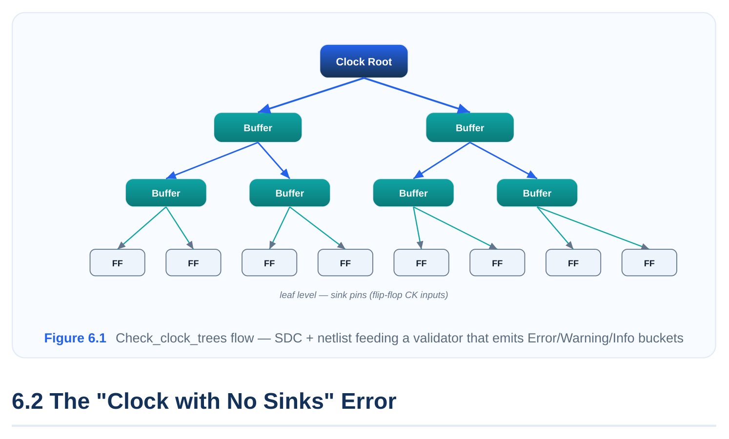
This is the most frequently encountered structural error, and it means exactly what it says: the tool traced the clock from its source but could not find a single sequential endpoint (register clock pin, macro clock input, or constrained output) at the leaf end of the tree. From the engine's perspective there is nothing to balance, so it cannot build a meaningful tree.
Common root causes
- A dangling or unconnected clock source — the create_clock points at a pin whose downstream net was never connected, often the result of an incomplete netlist or a missing IP instantiation.
- A gating cell that is permanently off — an enable tied to a constant, or an integrated clock-gating cell whose enable is logic-zero, blocks propagation so no sink is reachable.
- Propagation halted by a
set_clock_groups/case-analysis condition — case analysis on a mux select can steer the clock away from all sinks.
- An over-eager
set_clock_balance_points/ exception that excludes the only real sinks from the tree.
Resolution and the role of set_clock_balance_points
Resolution starts by tracing manually. Use the tool's clock-path reporting to walk from the source forward and find where propagation dies — a tied enable, a broken net, or a blocking exception. Fix the underlying cause (connect the net, free the gate enable, correct the case-analysis value).
set_clock_balance_points is relevant in two ways. First, it can cause the error if you previously de‐clared an internal pin as the only balance point and that pin no longer reaches the real registers. Second, it can fix a legitimate variant of the situation: when the true endpoints of a clock are nonstandard (for example, the clock terminates at a feedthrough pin or an output port that feeds an offchip device), you can explicitly nominate those pins as balance points so the tool treats them as the sinks it should balance to.
# Tell CTS where the real endpoints are when they are not ordinary registers
set_clock_balance_points \
-balance_points {u_io/clk_out_port u_macro/CLK_FB} \
-clock pll_out_clk
# Re-validate after declaring the balance points
check_clock_trees -clocks {pll_out_clk} -verbose
The key interview point: "no sinks" is almost never a tool bug. It is the tool honestly reporting that your declared clock and your actual logic do not meet. Treat it as a netlist/constraint integrity signal.
6.3 The "Invalid Master Source" Error
This error is specific to generated clocks. Every create_generated_clock must reference a master source via -source , and that source must be a pin or port that already carries a defined clock. "Invalid master source" means the referenced source either does not exist in the current netlist or carries no clock at the point you named.
Why it happens
Generated-clock validation is strict by design, because a generated clock inherits its waveform, period, and propagated latency from its parent. If the parent cannot be resolved, the entire derived waveform is undefined. Typical triggers:
- The
-sourcepin name is stale — the netlist was re-elaborated and the hierarchical name changed. - The master clock was never created (the
create_clockfor the parent is missing or commented out).
- The source points at a pin that is downstream of where the master clock actually exists, so no clock is present there.
- A divider/IP cell's output was declared as a generated clock but its input clock pin was never given a master clock.
Correction workflow
The fix is to re-establish a valid parent-to-child relationship:
# Master clock must exist first
create_clock -name ref_clk -period 9.6 [get_ports REFCLK]
# Generated clock's -source must name a pin that carries ref_clk
create_generated_clock -name div2_clk \
-source [get_pins u_div/CK] \
-divide_by 2 \
[get_pins u_div/Q]
# Confirm the master/source resolved correctly
report_clocks
check_clock_trees -clocks {div2_clk} -verbose
When debugging, always verify the master exists before questioning the generated clock. Run re‐ port_clocks and confirm the parent appears with a valid waveform; then confirm the -source pin lies on the parent's propagated network using a clock-path report. Nine times out of ten the master clock definition is the missing or misnamed piece, not the generated clock itself.
| Symptom in report | Likely cause | Fix |
|---|---|---|
| Source pin not found | Stale hierarchical name | Re-query the correct pin name |
| Source has no clock | Master create_clock missing | Define the master first |
| Source clock differs from ex‐ | -source points past a divider pected | Point -source at the parent's actual location |
| Generated clock period non‐ | Wrong -divide_by / -mul‐ sensical | Correct the ratio tiply_by |
6.4 Loop Detection
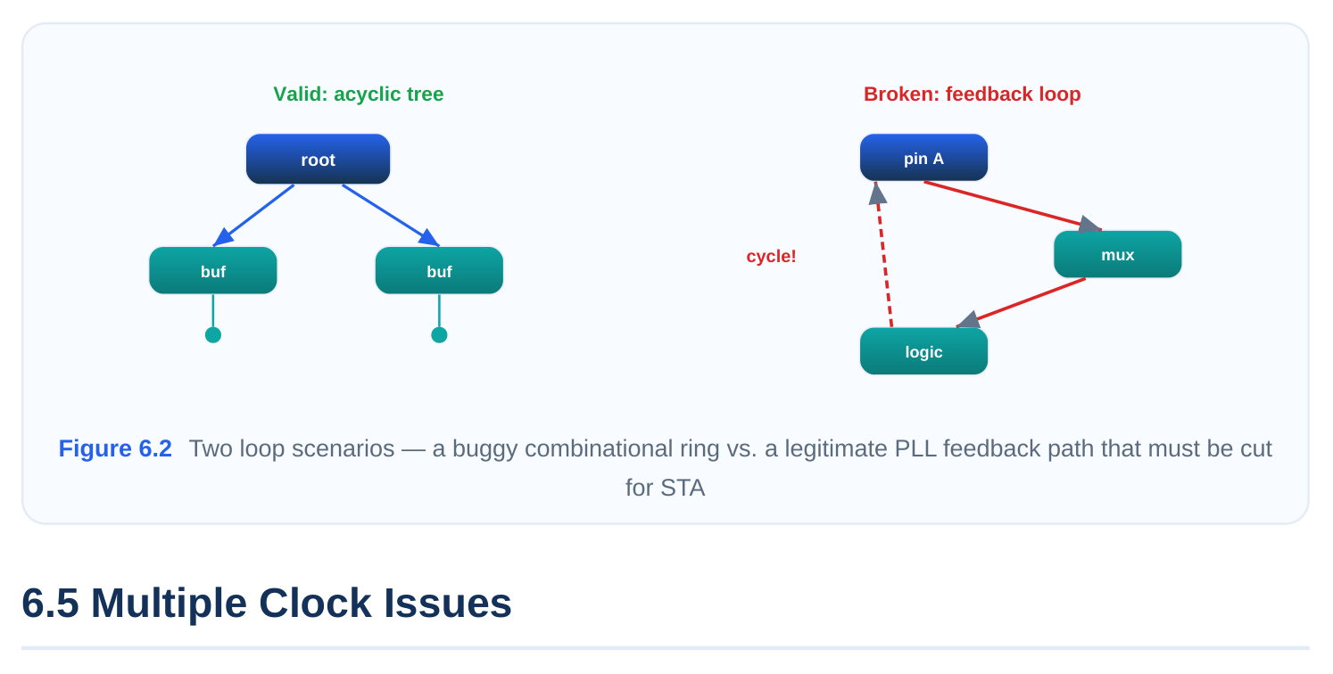
A clock network must be a directed acyclic graph from source to sinks. If the propagated clock path can return to a point it already visited, latency becomes undefined and the tool cannot assign a deterministic insertion delay. check_clock_trees detects these cycles and reports the offending net or instance.
Combinational feedback loops
The most common cause is a combinational loop in the clock path — for example, a clock routed through a gate whose output feeds back into one of its own upstream inputs, or a poorly written clockgating structure that creates a ring. These are genuine design issues: even outside CTS they cause oscillation risk and timing-analysis breakdown. When the tool reports a loop, it is doing you a favor by surfacing a real RTL or netlist defect.
PLL feedback analysis
Not every loop is a bug. PLLs are intentionally built around a feedback path: the output (or a divided version of it) is fed back to the phase detector to lock the loop. If you declare clocks naively across a PLL, the tool may flag the feedback path as a combinational clock loop. The correct treatment is to break the loop for static analysis — declare the master clock at the PLL output (or use the PLL's behavioral clock definition) rather than letting the analyzer trace through the physical feedback path, and apply the appropriate disabling on the feedback arc.
# Break the PLL feedback path so the analyzer does not see a loop
set_disable_timing [get_pins u_pll/FBIN]
# Define the real clock at the PLL output
create_generated_clock -name pll_clk \
-source [get_ports REFCLK] \
-multiply_by 8 \
[get_pins u_pll/CLKOUT]
check_clock_trees -clocks {pll_clk} -verbose
Distinguishing the two
The diagnostic question is always: is this loop intentional? If it traces through a PLL feedback or a de‐ liberately characterized macro, break it for analysis and move on. If it traces through ordinary standard-cell logic in your own RTL, treat it as a bug, find the offending gate from the verbose net name, and fix the source.
A register clock pin should normally see exactly one clock. When check_clock_trees reports that a sink is reached by multiple clocks, it is telling you that more than one clock waveform propagates to the same pin. CTS has to know which clock to balance that pin against, so this ambiguity must be resolved before tree building.
Why a pin sees multiple clocks
- A clock mux selects between two clocks at runtime, so both clocks structurally reach the down‐ stream pins. Until case analysis or clock-groups tell the tool only one is active in a given mode, it sees both.
- Overlapping clock definitions — two
create_clock/create_generated_clockcommands whose networks converge on the same logic. - Test-clock overlay — a scan or test clock that shares the same physical pins as the functional clock.
Identifying the affected registers
The verbose output lists the multiply-clocked pins. To analyze them systematically:
# Find sink pins reached by more than one clock
report_clocks -nosplit
foreach_in_collection p [all_registers -clock_pins] {
set clks [get_clocks -of_objects $p]
if {[sizeof_collection $clks] > 1} {
puts "MULTI-CLOCK: [get_object_name $p] -> [get_object_name $clks]"
}
}
Configuration requirements
The resolution depends on intent. If the multiple clocks are mutually exclusive in time (mux-selected modes), declare them as physically exclusive with set_clock_groups -physically_exclusive , or pin the active clock per mode with case analysis on the mux select. If both clocks genuinely run but are asynchronous, declare them asynchronous so CTS does not try to balance across the boundary, and ensure proper synchronizers exist in the RTL. The wrong move is to ignore the report — an unre‐ solved multiply-clocked pin leads CTS to make an arbitrary choice, and you get skew balanced to the wrong reference.
| Scenario | Correct declaration | CTS behavior after fix |
|---|---|---|
| Mux selects one of two | set_clock_groups -physic‐ | Balances only the active clock |
| clocks | ally_exclusive or case analysis | per mode |
| Two unrelated free-run‐ | set_clock_groups -asynchronous ning clocks | Builds independent trees, no cross-balancing |
| Functional + test clock | -logically_exclusive per mode on same pins | Balances the relevant clock in each mode |
6.6 Generated Clock Validation
Generated clocks deserve their own validation focus because they are where most subtle CTS-readi‐ ness bugs hide. Beyond the "invalid master source" error of 6.3, the tool checks several relationship properties that determine whether the generated clock's latency and waveform can be computed cor‐ rectly.
Master-source verification
The first validation is that the -source pin genuinely carries the named master clock at that location. It is not enough that the master clock exists somewhere; it must be present at the source pin you spe‐ cified. A frequent error is pointing -source at the output of a divider when you meant its input, which makes the generated clock reference a clock that does not yet exist at that node.
Combinational vs. sequential generated clocks
There is an important distinction:
- A combinational generated clock is derived by combinational logic only — for example, a clock passing through a buffer chain or an inverter. Its waveform is identical to (or simply inverted from) the master, with no edge-counting needed. These are usually trivial to validate.
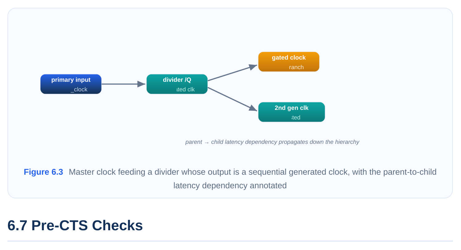
- A sequential generated clock comes from a state element such as a divider flop or a counter, where the output clock's period is a multiple/division of the master. Here the tool must reconcile the
declared -divide_by / -multiply_by / -edges against the actual sequential behavior. If your de‐ claration says divide-by-2 but the netlist implements divide-by-4, the latency and waveform will be wrong even though no hard error fires.
Parent-clock dependencies
A generated clock's propagated latency is computed relative to its parent. This creates a dependency chain: if the parent's network changes (gets re-buffered, re-routed, or its source moves), the child's latency must be recomputed. During CTS verification you confirm that every link in the chain resolves — parent exists, source pin carries parent, child waveform is consistent with the implementing logic.
# Inspect the full master/generated relationship and waveforms
report_clocks -attributes
# Verify a generated clock's source actually carries its master
get_clocks -of_objects [get_pins u_div/CK]   ;# should return the master clock
# Final structural pass over all generated clocks
check_clock_trees -verbose
The interview-grade summary: generated-clock validation is about three questions in order — does the parent exist, does the source pin carry the parent, and does the declared waveform match the real (combinational or sequential) implementation? Get those three right and the generated clock will balance cleanly.
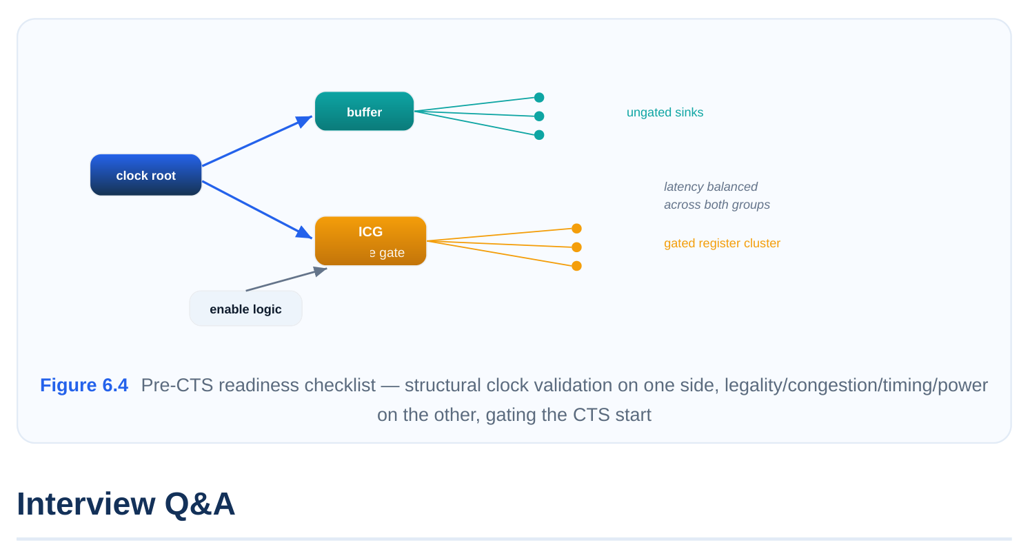
Clock-tree structural validation answers "can the tool build the tree?" The broader pre-CTS checks answer "is the design healthy enough that building it will actually help?" These run on the placed, preCTS database and cover legality, congestion, timing, and power. Skipping them is the classic cause of a CTS run that technically completes but lands the design in an unrecoverable state.
Placement legality via check_legality
CTS inserts and moves clock buffers, and it can only do that cleanly if the existing placement is legal — every cell on a legal site, no overlaps, no rows violated. check_legality confirms this. Running CTS on an illegal placement causes buffers to land in illegal locations or forces aggressive legalization that wrecks the carefully placed clock cells.
# Confirm placement is legal before CTS
check_legality -verbose
# If issues are reported, legalize then re-check
legalize_placement
check_legality
Congestion analysis
Clock buffers and clock routing consume routing resources. If the design is already congested before CTS, adding a buffer tree pushes it over the edge, producing detours that inflate clock latency and skew. A pre-CTS congestion check (a global-route-based congestion map or overflow report) tells you whether there is headroom. Hot spots near clock-heavy regions are a red flag: you may need to spread cells, add placement blockages around future clock-tree regions, or revisit floorplan before letting CTS proceed.
Timing estimation
Pre-CTS timing is run with ideal clocks (zero skew, zero insertion delay). This is your baseline. The purpose is to confirm the design closes — or is close to closing — before clock latency and skew are introduced. If pre-CTS setup is already badly violating with ideal clocks, CTS will only make it worse, because real insertion delay and skew eat into the timing budget. You want pre-CTS slack to have enough margin to absorb the skew and on-chip variation that CTS and post-CTS will add.
Power-budget estimation
The clock network is typically one of the largest dynamic-power consumers on the chip because it switches every cycle across many buffers. Estimating clock power before CTS — based on expected buffer count, total clock net capacitance, and toggle rate — lets you check against the power budget and decide on strategy: more clock gating, a leaf-level gating push, or constraining maximum buffer levels. Discovering a clock-power blowout after CTS is far more expensive to fix.
| Pre-CTS check | Question it answers | Tool/output | Consequence of skipping |
|---|---|---|---|
| check_legality | Is placement legal for buffer | Legality report | Illegal buffers, broken rows |
insertion?
| Congestion analys‐ | Is there routing headroom for | Global-route over‐ | Detoured clocks, latency/ |
|---|---|---|---|
| is | clock nets? | flow map | skew blowup |
| Timing estimation | Does the design close with ideal clocks? | Pre-CTS slack re‐ port | CTS pushes a failing design further off |
| Power estimation | Will the clock tree fit the power budget? | Clock-power estim‐ ate | Post-CTS power overrun, costly rework |
A clean pre-CTS gate is the combination of all of these: structurally valid clocks (sections 6.1–6.6) plus a legal, uncongested, timing-healthy, power-sane placed database. Only when both halves pass should you let the CTS engine start building.
should you treat each before CTS? An error is a structural defect — no sinks, invalid master source, a clock loop — that prevents the tool from building a correct tree; CTS will skip or mishandle that clock, so errors are gating and must be fixed. A warning flags a suspicious but tolerable condition (for example, a clock with very few sinks); CTS will proceed, but you should investigate to confirm it is not a real problem. The rule is: never run CTS with unresolved clock-tree errors.
source pin is actually connected by tracing the propagated path forward from the source. The propaga‐ tion usually dies at one of: a broken/unconnected net, a clock gate whose enable is tied off, a caseanalysis value steering the clock away, or an over-restrictive balance-point/exception. Fix the underlying cause. If the real endpoints are non-standard (a feedthrough or output port feeding off-
chip), declare them explicitly with set_clock_balance_points so the tool recognizes them as sinks, then re-run check_clock_trees .
clock error meaning the -source pin either does not exist or carries no clock. The fix order is parentfirst: confirm the master create_clock exists with a valid waveform via report_clocks , confirm the -source pin actually lies on that master's propagated network ( get_clocks -of_objects ), correct any stale hierarchical name, and only then re-validate the generated clock. Most of the time the master definition is the missing piece.
intentional. The analyzer is tracing through the physical feedback arc and seeing a cycle. The correct treatment is to break the loop for static analysis: disable timing on the feedback input pin, declare the real clock at the PLL output (typically a generated clock with the right multiply factor), and re-check. The distinguishing test for any loop is whether it runs through a PLL/characterized macro (break it) or through your own standard-cell logic (a real bug to fix).
skew, zero insertion delay) give you a clean baseline of the data-path timing before clock effects are introduced. You are checking that the design closes — or has enough positive slack margin — so that the real insertion delay, skew, and on-chip variation that CTS and post-CTS add can be absorbed. If the design already fails setup badly with ideal clocks, CTS will only make it worse, so you fix data-path timing first rather than expecting CTS to rescue it.
Key Takeaways
check_clock_trees -verboseis the structural gate before CTS: it validates reachability, source legality, acyclicity, and sink consistency, and its errors are non-negotiable blockers while warnings are advisory.- "Clock with no sinks" and "invalid master source" are integrity signals about your netlist/constraints, not tool bugs — debug by tracing propagation forward and by validating the parent clock before the generated clock.
- Treat clock loops by intent: break PLL/feedback loops for static analysis, but fix combinational loops in your own logic as genuine defects.
- Multiply-clocked pins must be resolved with the right
set_clock_groupsmode (physically/logically exclusive or asynchronous) or case analysis so CTS balances against the correct reference. - Generated-clock validation reduces to three ordered questions: does the parent exist, does the source pin carry it, and does the declared waveform match the real combinational or sequential im‐ plementation.
- A true pre-CTS green light combines structurally valid clocks with a legal (
check_legality), un‐ congested, timing-healthy (ideal-clock baseline), and power-sane placed database.
Comments
Leave a Reply