 ChipBuddy
← Home
ChipBuddy
← Home
Introduction to the Routing Engine
Routing is the stage of physical design where the abstract connectivity of a netlist finally becomes real, physical metal. Up to this point, the design has been a collection of placed cells with logical connections that exist only in a database. Routing is the engineering act of drawing actual wires on actual metal layers so that every pin that should be electrically connected truly is, while simultaneously respecting a punishing list of manufacturing rules, timing budgets, and reliability constraints. In modern modern EDA flows, the engine that performs this job inside the routing tool (and historically inside IC Compiler II) is the router, a router rebuilt from the ground up for advanced process nodes and large multicore machines. This chapter sets the stage. We will look at where routing lives in the flow, why the router exists in the form it does, the core problems routing has to solve, how the metal stack and routing directions work, the three classic phases of routing, the metrics by which we judge routing quality, and finally how multicore scalability turns an otherwise overnight job into a manageable one.
Where Routing Sits in the Physical-Design Flow
Physical design is a pipeline, and each stage hands a more refined database to the next. Routing sits late in that pipeline, after the design has already been floorplanned, placed, and clock-balanced, but before the final sign-off checks that decide whether the chip is manufacturable.
The ordering matters because every upstream stage constrains routing. Placement decides where cells sit, which directly determines how far wires must travel and how crowded certain regions become. Clock tree synthesis (CTS) builds the clock distribution network first, because the clock is the most timing-critical and most balance-sensitive net on the chip; you want it routed (or at least reserved) before signal routing fights for the same tracks. By the time signal routing begins, the clock skeleton is in place and the router's job is to connect the remaining data nets without disturbing what CTS carefully constructed. Routing Flow
Floorplan Placement CTS Routing Sign-off DRC, LVS)
| Flow stage | What it produces | Why routing depends on it |
|---|---|---|
| Floorplan | Die size, macro placement, power grid | Defines routable area and blockages |
| Placement | Legal cell locations | Sets wirelength and congestion landscape |
| CTS | Balanced clock network | Clock routed/reserved before signal nets |
| Routing (the router) | Physical wires for all signal nets | The subject of this handbook |
| Sign-off | Timing, DRC, LVS, EM/IR results | Verifies the routed design is shippable |
After routing completes, the design moves into sign-off: static timing analysis (STA) with real parasitics extracted from the routed wires, design rule checking (DRC), layout-versus-schematic (LVS), and reliability checks like electromigration (EM) and IR drop. Routing is therefore the last major constructive step. Everything after it is mostly verification, so the quality of the routing largely decides whether sign-off passes cleanly or sends you back for painful iterations.
What the router Is
the router is modern EDA's flat, multithreaded, multicore routing engine. The word "flat" is important: rather than routing one hierarchical block at a time and stitching results together, the router can operate across the entire routable area as a single problem, which avoids artificial seams and gives the engine global visibility into congestion and timing. Three design goals shaped the router:
Built for Advanced Nodes (sub-40nm)
At older nodes, design rules were relatively simple: keep wires a minimum width apart and you were mostly done. At 40nm and below, the rule set explodes. You encounter complex spacing tables that depend on wire width and run length, end-of-line rules, minimum-area rules, via enclosure rules, and double-patterning coloring constraints at the most advanced nodes. the router was architected to treat these rules as first-class citizens rather than as afterthoughts patched onto an old engine.
DFM-Aware Routing
Design for Manufacturability (DFM) means routing not just to a passing DRC, but to a layout that actually yields well in the fab. the router can optimize for wire spreading (pushing wires apart where room exists to reduce shorts from lithography variation), via doubling or redundant vias (adding a parallel via so a single via failure does not open the net), and wider wires on long nets. These are not strictly required for correctness, but they dramatically improve yield, and a modern router bakes them into the routing decisions instead of leaving them to a separate cleanup tool.
Concurrent, Multicore Architecture
the router was written to scale across many CPU cores. Routing a large block is enormously computeintensive, and a router that only uses one core would take impractically long on a multimillion-instance design. We will return to this in the scalability section, but it is core to the router's identity, not a bolt-on feature.
The Problems Routing Solves
It is tempting to think of routing as "just connect the dots," but the difficulty is that several objectives pull against each other simultaneously. A good router balances all of them at once.
| Problem | What it means | What goes wrong if ignored |
|---|---|---|
| Connectivity | Every net's pins must be electrically joined | Opens; the chip is functionally broken |
| Design rules | Wires must obey spacing, width, via, EOL | DRC violations; not manufacturable |
rules
| Congestion | Demand for tracks must not exceed supply | Unroutable regions, detours, DRCs |
|---|---|---|
| Timing | Critical paths must meet setup/hold post-route | Chip fails at target frequency |
| Signal integrity | Crosstalk between neighbors kept in check | Glitches, delay variation, functional |
fails
Manufacturability Yield-friendly geometries (vias, spreading) Low yield even if DRC-clean
Connectivity Under Design Rules
The baseline job is to connect all nets. But the connection must be legal. Two wires that touch where they should not are a short; a net that fails to connect is an open. Every segment the router draws must satisfy the technology's design rules, encoded in the technology file and DRC decks. The combination of "connect everything" and "break no rules" is already an enormous constraintsatisfaction problem on a large chip.
Congestion Management
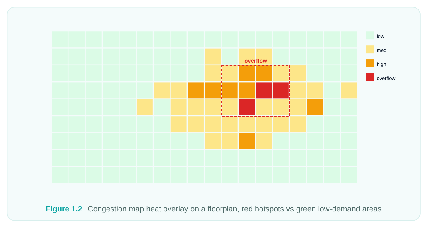
Each routing layer offers a finite number of tracks, the parallel lanes along which wires run. When more nets want to cross a region than there are tracks to carry them, that region is congested. The router must either find detours, push some nets to other layers, or, in severe cases, the design must go back to placement to relieve the hotspot. Managing congestion is one of the central intelligences of a modern router.
Timing, Signal Integrity, and Manufacturability
Once wires exist, they have real resistance and capacitance, which means real delay. Routing therefore has to be timing-aware: critical nets should get short paths, wider wires, or higher (less resistive) metal layers. Adjacent parallel wires couple capacitively, so a switching aggressor can inject noise into a quiet victim, the phenomenon of crosstalk. And as discussed, manufacturability pushes the router toward yield-friendly geometries. All of this happens concurrently with simply getting nets connected.
The Metal Stack and Preferred Routing Directions
Chips route on a stack of metal layers, conventionally named M1, M2, M3, and upward, separated by insulating dielectric and connected vertically by vias. Lower layers (M1, M2) are thin, fine-pitched, and resistive; they are ideal for short local connections. Upper layers are thicker, wider-pitched, and far less resistive; they are reserved for long-distance signals, power distribution, and the clock. A foundational convention is that adjacent layers route in alternating preferred directions. If M2 prefers horizontal routing, M3 prefers vertical, M4 horizontal again, and so on. This alternation is what makes it possible to get from any point to any other: a horizontal run on one layer hops through a via to a vertical run on the next, weaving across the chip like a street grid with one-way avenues. Routing against a layer's preferred direction is allowed for short jogs but is discouraged because it consumes tracks inefficiently and tends to create congestion.
| Layer group | Typical use | Width / pitch | Resistance |
|---|---|---|---|
| Lower (M1–M2) | Local cell connections, pins | Narrow, fine | High |
| Mid (M3–M6) | General signal routing | Medium | Medium |
| Upper (top metals) | Long nets, clock, power straps | Wide, coarse M6 M5 M4 M3 M2 M1 | Low vertical horizontal vertical horizontal vertical horizontal |
alternating preferred directions, stitched by vias (dark squares)
Figure 1.3 Side cross-section of metal stack M1 to top metal with vias, plus a top view showing alternating H/V
preferred directions The router consults a routing layer range for each net or net class. A high-speed bus might be constrained to mid or upper layers to control delay and crosstalk, while ordinary nets are free to use whatever the congestion picture allows.
Global Routing, Track Assignment, and Detail Routing
the router does not solve the whole problem in one shot. It decomposes routing into phases, each handing a progressively more concrete result to the next. We introduce them here and dedicate later chapters to the details.
Global Routing
Global routing is the planning phase. The router divides the chip into a coarse grid of rectangular regions, often called global routing cells or gcells, and decides which gcells each net should pass through. It does not draw exact wires yet; it draws a plan and, critically, estimates congestion by comparing the routing demand through each gcell boundary against the available track capacity. If global routing reports overflow, you know you have a congestion problem before wasting time on detailed wires.
Track Assignment
Track assignment takes the global plan and commits long, straight segments of nets to specific tracks on each layer, following preferred directions. It is an intermediate step that turns the loose gcell-level plan into mostly-placed wire segments, leaving the messy local connections (pin access, jogs, via stacks) for the final phase. Track assignment is where much of the long-haul wiring gets laid down quickly and cleanly.
Detail Routing
Detail routing is the finisher. It connects the remaining pieces, accesses every pin precisely, inserts vias, and, most importantly, cleans up every design-rule violation until the layout is DRC-correct. This is the most rule-intensive and compute-heavy phase, and it is where the router's advanced-node rule engine earns its keep.
# A typical end-to-end routing invocation in the routing tool.
# auto_route runs global routing, track assignment, and detail routing
# as one orchestrated sequence.
auto_route
# Or drive the phases explicitly when you need finer control:
global_route
assign_tracks
detail_route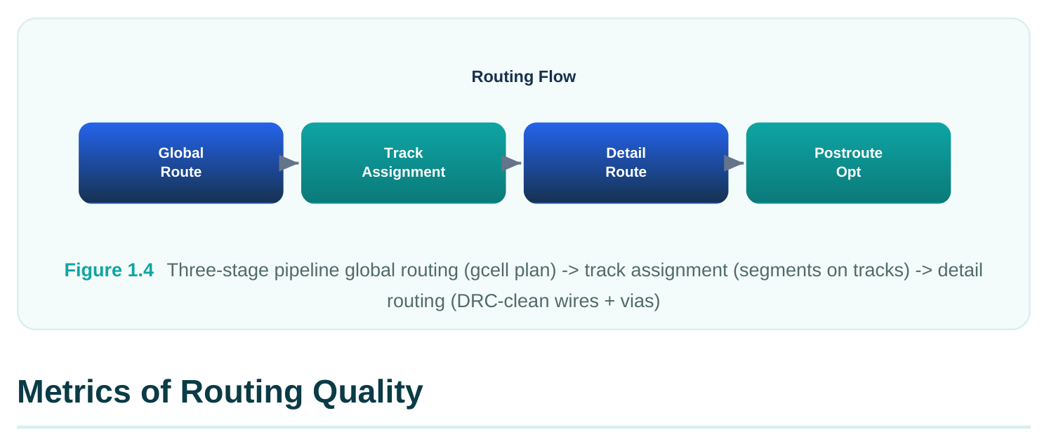
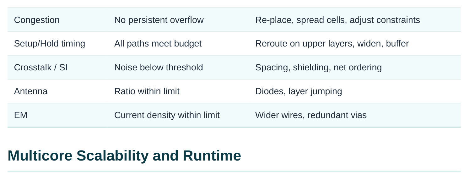
A routed design is judged on several axes at once. Passing one while failing another is not success. Here are the metrics that matter and what each one tells you.
DRC Cleanliness
The most basic pass/fail gate: the routed layout must have zero design-rule violations. A handful of remaining shorts or spacing errors means the chip cannot be manufactured as drawn. Detail routing's primary mission is to drive DRC count to zero.
Congestion
Even a DRC-clean route can be a warning sign if it required heroic detours through congested regions. Congestion is measured by overflow, the amount by which routing demand exceeds track supply at gcell boundaries. Persistent overflow predicts DRC trouble and timing trouble, and often points back to a placement that needs fixing.
Timing After Routing
Once real parasitics exist, you re-run timing. Both setup (is the signal fast enough?) and hold (is it not too fast, arriving before the clock edge it should follow?) are checked. Routing can degrade timing through long detours and high-resistance paths, so postroute optimization frequently reroutes critical nets onto better layers or wider wires.
Crosstalk / Signal Integrity
Parallel neighboring wires couple. SI analysis checks whether aggressor nets inject enough noise into victims to cause functional failures or unacceptable delay shifts. Fixes include increasing spacing (non-default spacing), shielding sensitive nets with grounded wires, and net ordering.
Antenna
During fabrication, partially built metal can accumulate charge that damages the thin gate oxide of connected transistors, the antenna effect. The router must keep the ratio of exposed conductor area to gate area within limits, typically by inserting antenna diodes or jumping the net up to a higher layer to break the long antenna.
Electromigration (EM)
Wires carrying high current density over time suffer atoms physically migrating, eventually opening the wire. EM-aware routing widens high-current nets and uses redundant vias so the design survives its rated lifetime.
| Metric | Pass criterion | Common fix if failing |
|---|---|---|
| DRC | Zero violations | More detail-route iterations |
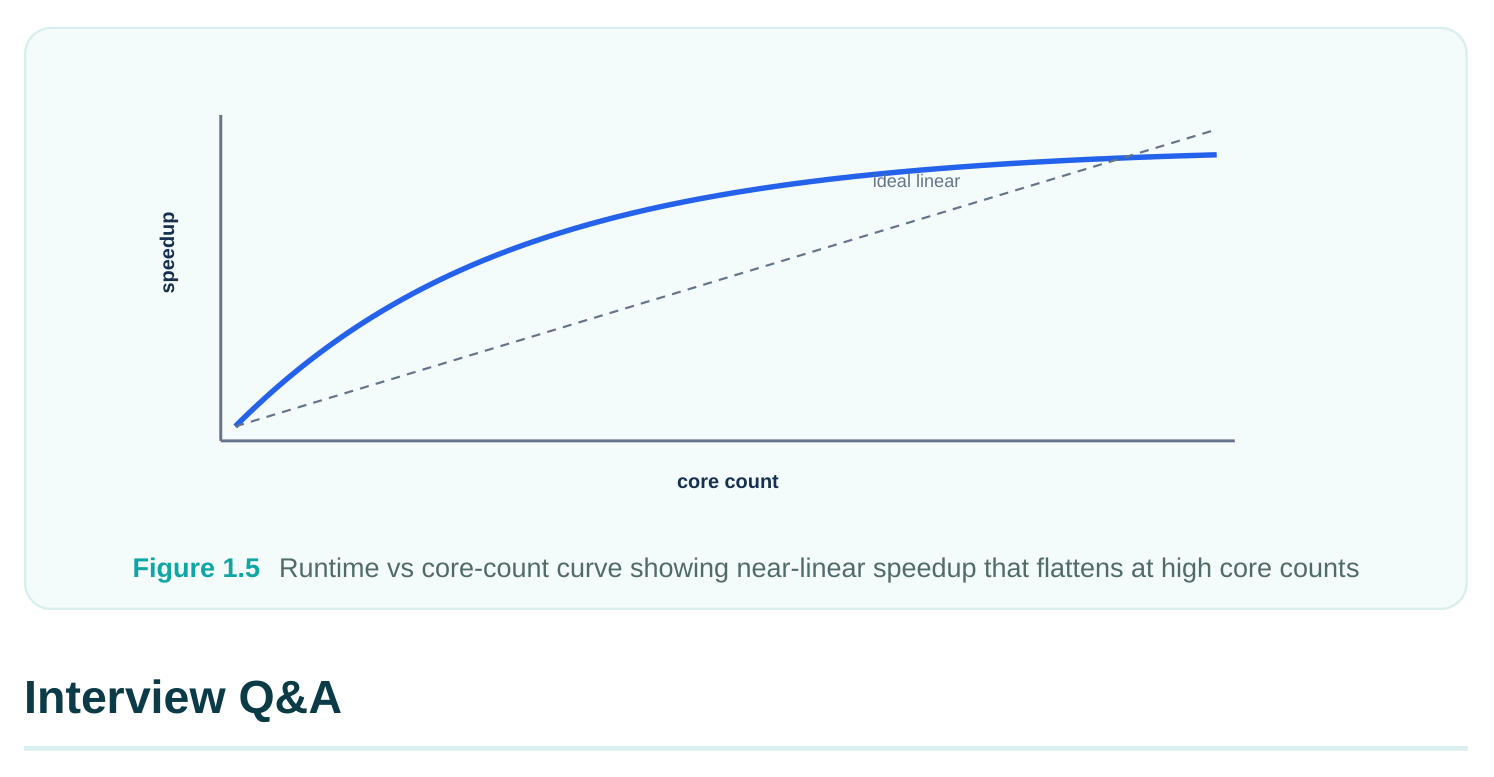
The reason the router exists in its current form is runtime. Routing a chip with millions of instances and tens of millions of net segments is one of the heaviest computations in the whole flow. A purely serial router would run for days, which is unacceptable when designers need several iterations. the router parallelizes by partitioning the routing area and distributing work across CPU threads and cores, so that many regions are routed concurrently while a coordination layer keeps the results globally consistent at the boundaries. The practical effect is close to linear speedup over a sensible range of cores: doubling the cores roughly halves the runtime, until coordination overhead and sharedresource limits flatten the curve.
# Tell the tool how many cores/threads it may use before routing.
# Match this to the physical cores available on the host.
set_host_options -max_cores 16
# Verify the setting the tool will honor.
report_host_options
# Then run routing; the router distributes the work across those cores.
auto_route
A few runtime realities are worth internalizing for interviews and for practice:
- More cores help, but with diminishing returns. Past a point, you are paying coordination cost for little gain.
- Memory matters as much as cores. Large designs need large RAM; thrashing to disk destroys any multicore benefit.
- A congested or rule-heavy design routes far slower than a clean one, because detail routing iterates harder to resolve violations. Good placement is the cheapest way to speed up routing.
- Runtime and quality trade off through effort settings; pushing for the last few DRCs or the tightest timing costs disproportionate time.
and skew-sensitive structure on the chip, so it is built first and given priority access to routing resources. If signal routing ran first, it would consume tracks the clock tree needs and force the clock onto inferior paths, hurting skew and timing. Running CTS first lets the clock claim its routes (or reservations), after which signal routing fills in around it.
phase: it divides the chip into coarse gcells and decides which gcells each net traverses, while estimating congestion. It does not draw exact, rule-correct wires. Detail routing is the implementation
phase: it lays down precise wire geometries, accesses pins, inserts vias, and resolves every designrule violation so the layout is DRC-clean.
horizontal and vertical preferences lets the router move freely in both dimensions, weaving across the chip by hopping through vias between layers, much like a grid of one-way streets. It also uses track capacity efficiently and reduces congestion, since same-direction routing on neighboring layers would waste tracks and create blockages.
matters. Timing (setup/hold must still pass once real wire parasitics are extracted, or the chip fails at speed), crosstalk/SI (coupling between neighboring wires can inject noise that causes functional or delay failures), and antenna (charge accumulation during fabrication can damage gate oxide, so antenna ratios must stay within limits). EM and congestion are equally valid additional answers.
Key Takeaways
- Routing converts logical connectivity into physical metal, and it sits late in the flow, after floorplan, placement, and CTS, but before sign-off, so its quality largely determines whether sign-off passes.
- the router is modern EDA's flat, multicore, multithreaded router, purpose-built for sub-40nm rule complexity and DFM-aware optimization such as via doubling and wire spreading.
- Routing simultaneously balances connectivity, design rules, congestion, timing, signal integrity, and manufacturability; these objectives compete, and a good router trades them off intelligently.
- The metal stack alternates preferred routing directions layer to layer, with thin resistive lower layers for local nets and thick low-resistance upper layers for long nets, clock, and power.
- Routing proceeds in phases, global routing (planning and congestion estimation), track assignment (segments on tracks), and detail routing (precise, DRC-clean geometry).
- Routing quality is judged on DRC, congestion, post-route timing, crosstalk, antenna, and EM, while multicore scalability keeps runtime practical, with diminishing returns past a sensible core count.
Comments
Leave a Reply