 ChipBuddy
← Home
ChipBuddy
← Home
Routing Clock Nets
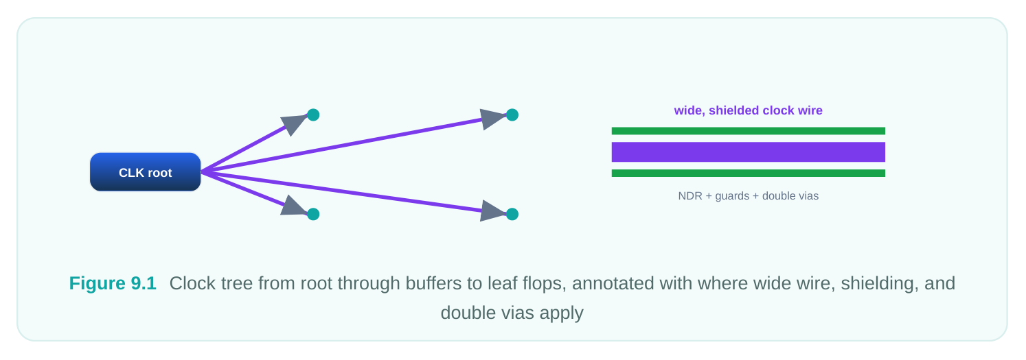
Of all the nets a router touches, clock nets are the ones that least tolerate being treated like everything else. A signal net that arrives a few picoseconds late or picks up a little crosstalk usually has slack to absorb the damage. A clock net does not have that luxury: every flip-flop in its fanout latches data on the edge it delivers, so any distortion of that edge propagates directly into the timing budget of thousands of paths at once. When you route a clock badly, you don't create one violation — you create a systematic bias that shows up everywhere downstream. That is why the routing tool (and the router engine underneath it) gives clock nets their own routing machinery: nondefault routing rules, layer restrictions, shielding, and redundant vias, all coordinated so that the careful balancing work done during clock tree synthesis survives the trip through detailed routing intact. This chapter walks through why clocks are special, how you express that specialness as routing rules, and how those rules connect back to the intent your CTS engine already baked into the tree.
Why Clock Nets Deserve Special Treatment
Four physical concerns drive everything we do to clock routing. It helps to keep them straight, because the rules you write are essentially a response to each one. The first is skew. The whole premise of synchronous design is that the clock edge arrives at every sequential element at very nearly the same time. CTS spends enormous effort balancing the insertion delay across leaf pins, but those delays are computed against an assumed wire model. If the router gives one branch a thin, resistive wire on a congested low-metal layer and another branch a fat wire on an upper layer, the real delays diverge from the balanced estimate and skew creeps back in. Uniform, predictable RC is therefore not a luxury — it is the thing that keeps the CTS result honest. The second is resistance and capacitance magnitude. Clock nets switch every cycle, often at the highest frequency on the die, so their delay and their dynamic power both scale with RC. Wider wires lower resistance; routing on thicker upper-metal layers lowers it further. Lower RC means sharper edges, less insertion delay, and a smaller distortion of the duty cycle. The third is signal integrity. Because the clock is the timing reference, any noise coupled onto it is uniquely damaging — a glitch on a clock can cause a false latch, and crosstalk-induced delay variation directly becomes jitter. We protect clocks both by giving them extra spacing from aggressor nets and, for the most sensitive nets, by shielding them with grounded wires. The fourth is electromigration and reliability. High switching activity means high average current density, especially through vias. A single via carrying the full current of a clock branch is an EM risk; redundant (double or multiple) vias spread that current and dramatically improve via reliability and yield.
| Concern | Physical cause | Routing response |
|---|---|---|
| Skew | Non-uniform wire RC across branches | Consistent NDR, restricted layer set |
| RC / delay | High switching frequency | Wider wires, upper-metal layers |
| Signal integrity | Crosstalk, coupled noise | Extra spacing, shielding |
| EM / reliability | High current density at vias | Redundant / double vias |
Nondefault Routing Rules for Clocks
A nondefault routing rule (NDR) is the vehicle for almost all of the above. It is a named bundle of physical attributes — wire width, spacing, and via behavior — that you attach to specific nets so the router builds their geometry differently from the default tech-rule wires. You create one with define_routing_rule . The common knobs are -widths (per-layer wire width, usually expressed as a multiple of the minimum), -spacings (per-layer edge-to-edge spacing), and - default_reference_rule so anything you don't override falls back to the foundry minimum. A typical "2W2S" clock rule — double width, double spacing — looks like this:
# Define a double-width, double-spacing clock routing rule
define_routing_rule CLK_2W2S \
-widths {M4 0.112 M5 0.112 M6 0.144 M7 0.144} \
-spacings {M4 0.112 M5 0.112 M6 0.144 M7 0.144} \
-default_reference_rule
# Optional: tie redundant-via behavior to this rule's vias
set_attribute [get_routing_rules CLK_2W2S] use_double_vias true
The wider wire cuts resistance and improves EM headroom; the wider spacing pushes potential aggressors away, reducing coupling capacitance and crosstalk. The cost is area and routing resource, which is exactly why you apply these rules selectively to clocks rather than globally. Once the rule exists, you bind it to nets with apply_routing_rule . You can target the clock nets explicitly, or — more robustly — let the tool collect them by querying the clock network:
# Collect every net in the clock network, then apply the NDR
set clk_nets [get_nets -of_objects [all_fanout -clock_tree -flat -only_cells]]
apply_routing_rule $clk_nets \
-rule CLK_2W2S \
-min_routing_layer M4 \
-max_routing_layer M7
A few practical notes. The leaf-level nets — the short stubs from the last buffer to the flop clock pins — usually should not carry the heavy 2W2S rule, because forcing wide wire and high-layer access on a sub-micron stub wastes resources and can even hurt pin access. It is common to apply the strong rule to trunk and intermediate nets and let leaf nets use the default or a lighter rule. Be deliberate about which nets apply_routing_rule actually catches.
set_clock_routing: The Clock-Aware Front Door
While define_routing_rule / apply_routing_rule are general-purpose, the routing tool also exposes set_clock_routing , which is purpose-built to describe clock routing in one place and is understood by both the CTS and routing engines. It lets you state, per clock or globally, which NDR
governs the clock, what layer range the clock is allowed to live on, and whether shielding should be applied — all as clock intent rather than as a generic net override.
# Describe how the clock network should be routed
set_clock_routing \
-net_type {trunk} \
-rule CLK_2W2S \
-min_routing_layer M5 \
-max_routing_layer M7 \
-shield_route true
# A lighter rule for the leaf segments
set_clock_routing \
-net_type {leaf} \
-rule CLK_1W2S \
-min_routing_layer M3 \
-max_routing_layer M5
The advantage of going through this command is coordination. CTS uses the same routing-rule and layer information when it estimates delays and balances the tree, so the assumptions it optimizes against match the constraints the router will later honor. When trunk and leaf are described separately, you get the natural pattern of a robust, shielded backbone on thick metal feeding lighter, lower-layer stubs at the leaves — which is exactly how a well-built clock tree wants to be physically realized.
Restricting Clocks to Preferred Metal Layers
Layer choice is one of the highest-leverage decisions for clocks. Lower metals (M1–M3) are thin, resistive, and densely packed with signal routing and pin access — a hostile environment for a lowRC, low-noise net. Upper metals are thicker, lower-resistance, and less congested, which makes them the natural home for clock trunks. By contrast, the topmost redistribution-style layers are often reserved for power and are too coarse (their pitch and via stack make fine clock routing impractical), so clocks usually want the upper-but-not-top band. You constrain this with the -min_routing_layer / -max_routing_layer arguments shown above. The goal is twofold: keep RC low and, just as importantly, keep it uniform across branches so the CTS balance holds. Two branches both routed on M5/M6 behave alike; one on M2 and one on M6 do not.
| Layer band | Typical role for clocks | Rationale |
|---|---|---|
| M1–M2 | Avoid for trunks | High R, congested, pin-access only |
| M3–M4 | Leaf / short connections | Acceptable RC over short distances |
| M5–M7 | Trunk and main distribution | Low R, thicker metal, shieldable |
| Top / RDL | Avoid | Reserved for power, too coarse |
A common refinement is to define the preferred direction and confine clock detours: you don't want the router dropping a clock down to M2 just to dodge a small blockage, because that local excursion injects exactly the RC non-uniformity you were trying to eliminate. Tight min/max layer bounds prevent that.
Shielding and Redundant Vias
For the most timing-critical or noise-sensitive clocks — a high-speed core clock, a clock feeding analog or mixed-signal blocks — width and spacing alone may not be enough. Shielding routes grounded (or VDD-tied) wires alongside the clock so that coupling goes to a quiet reference rather than to a switching aggressor. The shield wires hold a constant potential, so the clock's coupling capacitance becomes predictable and crosstalk-induced jitter drops sharply. You can request shielding through set_clock_routing -shield_route true for the integrated flow, or invoke the dedicated shielding step directly. The two-sided shield is the strong form; a one-sided shield is a compromise when resources are tight.
# Apply two-sided ground shielding to the clock trunk nets
set clk_trunks [get_nets -filter "net_type == trunk" $clk_nets]
create_shield \
-nets $clk_trunks \
-shield_net VSS \
-layers {M5 M6 M7} \
-both_side true \
-extension_with_via true
Shielding is expensive in routing area — each shielded clock wire effectively consumes the track on either side of it — so reserve it for the nets that genuinely need it rather than the whole tree. Redundant vias address the EM and reliability side. Every time the clock changes layers, the via stack carries the full branch current; a single cut is both an EM hotspot and a yield liability (one void can open the net). Replacing single vias with double or multiple vias on clock nets lowers current density per cut and provides redundancy if one cut is defective. You can request this as part of the routing rule (the use_double_vias attribute shown earlier) so that every via the clock router places for that rule is automatically doubled, and you can also run a dedicated redundant-via optimization that upgrades existing single vias post-route:
# Prefer double vias for clock nets during routing,
# then upgrade remaining single vias after detailed route
set_tool_option -name detail.insert_diagonal_wires -value false
set_tool_option -name common.concurrent_redundant_via_mode -value clock
auto_route
# Post-route redundant via insertion focused on clock nets
insert_redundant_vias -nets $clk_nets
The order matters: you want the router to prefer redundant vias as it builds the clock, then a cleanup pass to convert any singles that slipped through where space was tight.
Preserving CTS Intent Through Routing
The most important conceptual point in this chapter is that routing does not invent the clock structure — CTS does. Clock tree synthesis decides the buffering, the branching topology, and the balanced insertion delays. Detailed routing's job is to physically realize that topology without breaking the balance the CTS engine worked to achieve. Everything above — consistent NDRs, restricted and uniform layers, shielding, redundant vias — exists to make the routed RC match the RC that CTS assumed. This is why the integrated set_clock_routing flow is valuable: the same rule and layer description feeds both engines, so the delays CTS optimizes against are the delays routing produces. When the two disagree — say CTS assumed thick-metal trunks but the router was free to use M2 — you get post-route skew that looks like it appeared out of nowhere. The fix is almost always to tighten the routing constraints so the physical implementation tracks the CTS model. Routing Flow
| Global | Track | Detail | Postroute |
|---|---|---|---|
| Route | Assignment | Route | Opt |
Figure 9.2 Flow showing CTS balanced tree -> NDR + layer rules + shield + double via -> routed clock with
preserved skew A sound checklist when handing the clock from CTS to route:
| Stage | What to verify |
|---|---|
| Before route | NDRs created, bound to correct trunk/leaf nets, layer bands set |
| Before route | Shield nets (VSS/VDD) identified, shield rule attached to critical clocks |
| During route | Redundant-via preference enabled for clock nets |
| After route | Skew and insertion delay re-checked against CTS values |
| After route | Clock SI (crosstalk delta delay) and via EM clean |
If post-route skew has drifted from the CTS estimate by more than your tolerance, that is the signal that the routed RC diverged from the modeled RC — and the levers to pull are exactly the ones in this chapter.
Interview Q&A
Because the damage from default routing is systematic, not local. A clock net feeds thousands of sequential elements, so non-uniform RC across its branches reintroduces skew everywhere at once, and crosstalk on the clock becomes jitter on every captured edge. Postroute "cleanup" can't recover balance that was never built in — the wire widths, layers, and spacing have to be right while the geometry is created. You apply NDRs and layer restrictions up front precisely because the clock is the global timing reference and there is no slack to absorb mistakes.
apply_routing_rule is a general mechanism that binds any NDR to any collection of nets — it doesn't know or care that the nets are clocks. set_clock_routing is clock-aware: it describes routing intent per clock (trunk vs leaf), including the NDR, the allowed layer range, and shielding, in a form that both the CTS and routing engines consume. The practical benefit is coordination — CTS estimates delays using the same rules the router will honor, so the balanced tree survives detailed routing instead of drifting.
layers? Lower layers are thin, resistive, and congested, which hurts both RC magnitude and uniformity. The very top layers are typically reserved for power distribution and have coarse pitch and large via stacks that make fine, balanced clock routing impractical. The upper-middle band (e.g., M5–M7 in a typical stack) gives you thick, low-resistance metal that is still routable and shieldable, and confining all branches to the same band keeps RC uniform so the CTS skew balance holds.
You shield the most noise-sensitive or highest-frequency clocks — core clocks, clocks crossing noisy regions, or clocks feeding sensitive analog/mixed-signal blocks — where width and spacing alone can't guarantee the crosstalk and jitter budget. Two-sided ground shielding ties the coupling to a quiet reference, making the clock's capacitance predictable and slashing crosstalk-induced jitter. The cost is routing area: a shielded wire consumes the tracks on both sides, so you reserve shielding for the nets that truly need it rather than blanketing the whole tree.
Key Takeaways
- Clock nets need special routing because skew, RC magnitude, signal integrity, and EM all hit the clock harder than any signal net — and the damage is systematic across the entire fanout.
- Nondefault routing rules (
define_routing_rule+apply_routing_rule) deliver wider wire, extra spacing, and double-via behavior; apply the heavy rules to trunks and lighter rules to leaf stubs. set_clock_routingis the clock-aware front door that hands the same NDR, layer-range, and shielding intent to both CTS and the router, keeping their assumptions consistent.
- Confine clocks to upper-but-not-top metal layers for low and, crucially, uniform RC; tight min/max layer bounds stop the router from dropping clocks to thin lower metal.
- Shield the most critical clocks with grounded wires and use redundant/double vias everywhere on the clock to control crosstalk-induced jitter and via EM.
- Routing's job is to preserve CTS intent: if post-route skew drifts from the CTS estimate, the routed RC diverged from the modeled RC, and the rules in this chapter are the levers to bring them back into agreement.
Comments
Leave a Reply