 ChipBuddy
← Home
ChipBuddy
← Home
Inserting Via Ladders
Inserting Via Ladders
A via ladder is one of those small structural tricks that quietly solves two unrelated-sounding problems at once: getting the router cleanly onto a difficult pin, and keeping that connection alive against electromigration. If you have spent any time staring at congested standard-cell rows or wrestling with a high-current power pin that keeps failing EM checks, you already understand the pain. Via ladders are the disciplined, rule-driven answer the routing tool gives you, and this chapter walks through what they are, how the rules are defined, and exactly what insert_via_ladder will and will not do for you.
What a Via Ladder Actually Is
Picture a pin sitting on, say, metal layer M1. The router needs to land on that pin and then climb up the metal stack to reach the routing layers where it can actually run wires across the block. Normally that climb happens wherever the router decides, with a single cut via at each layer transition, placed opportunistically. A via ladder replaces that ad-hoc climb with a pre-built, deliberately stacked column of vias and metal — a vertical "ladder" rising from the pin through several metal layers, with each rung being a via array (or a controlled set of cuts) and each step being a short metal segment.
EM via ladder — wide base, tapering up M6 M5 M4 M3 M2
M1 high-current pin single opportunistic via climb There are two distinct motivations, and it helps to keep them separate in your head because they drive different rule choices. The first is pin access. On advanced nodes, lower-layer pins are tiny, the surrounding tracks are scarce, and the router frequently struggles to find a legal landing that also leaves room to escape. By pre-placing a robust, well-formed via stack on the pin before detail routing, you give the router a generous, predictable structure to connect into. The escape becomes easier, the connection is more uniform, and you avoid the marginal single-cut landings that turn into DRC headaches or post-route hotspots. The second is electromigration robustness. A single via cut can only carry so much current before the current density through that cut exceeds the EM limit. High-current nets — clock roots, strong drivers, power-sensitive signal pins — can blow past that limit at a single transition. The fix is to widen the conduction: use a via array with many parallel cuts so the current splits across them, and stack those arrays through several layers so no single transition becomes the bottleneck. That stacked, multi-cut structure is exactly an EM via ladder. So the same physical object — a stack of vias and metal — serves pin access when you optimize it for routability, and serves EM when you optimize it for current capacity. The rules let you express both intents.
Defining Via Ladder Rules and Constraints
A via ladder rule is a named recipe. It specifies which via masters or via-array patterns to use at each layer transition, how the metal between rungs should be shaped, the bottom and top layers the ladder should span, and any tapering behavior. A via ladder constraint, by contrast, is the binding of a rule to a set of objects — which pins, which nets, which conditions — so the tool knows where to apply that recipe. Think of it as a two-part contract. The rule answers "what does a good ladder look like here?" and the constraint answers "where do I want one?" Keeping them decoupled is what lets you reuse a single
well-tuned EM rule across every high-current pin in the design, or apply a lightweight access rule to an entire layer's worth of pins. The rules themselves can come from more than one source, and which source you use depends on how your library and methodology are set up.
| Rule source | What it provides | Typical use |
|---|---|---|
| Tcl script | Rules authored directly in the | Block-level tuning, |
| ( define_via_ladder_rules ) | session, inline | experimentation, EM-specific |
ladders
| Library / technology data | Foundry- or library-defined | Sign-off-aligned, reusable across |
|---|---|---|
| ladder definitions | designs | |
| XML rule file | Externally generated or vendor- supplied ladder definitions | Hand-off between teams, automated flows |
The Tcl path is the most hands-on. You author the rule in the session, attach it, and it lives with your script. The library-model and XML paths bring in definitions that someone else — a library team, a foundry kit, an upstream generation step — has already validated, which is what you want when the ladder geometry must match sign-off assumptions. In practice many flows mix the two: pull the baseline structures from library data, then layer block-specific EM rules on top with a script.
Authoring Rules with a Script
The most direct way to define a rule is define_via_ladder_rules . You give the rule a name, tell it the layer span, and describe how the rungs are built. Here is a straightforward access-oriented ladder that climbs from the pin layer up to M4.
# Define a pin-access via ladder spanning M1 up to M4
define_via_ladder_rules \
-rule_name access_m1_to_m4 \
-from_layer M1 \
-to_layer M4 \
-via_master {VIA12_2x1 VIA23_2x1 VIA34_2x1} \
-metal_strategy follow_pin
# Confirm what the tool registered
query_via_rules access_m1_to_m4
A few things are worth calling out. The -from_layer / -to_layer pair establishes how tall the ladder is — here three transitions, M1->M2->M3->M4. The -via_master list names the via array used at each transition; using a 2x1 array rather than a single cut is already a step toward robustness. After defining anything, get in the habit of running query_via_rules to read back what the tool actually registered, because a typo in a layer name or master name will silently produce a rule that does nothing useful later.
Generating Rules for a Layer Range
Authoring every transition by hand is tedious and error-prone, especially when you want a ladder that simply climbs as high as a given upper metal layer. The generation flow lets you describe the intent — span these layers, use this kind of structure — and have the tool fill in the per-transition detail. This is the natural way to produce a family of ladders covering, say, every pin layer up through M5.
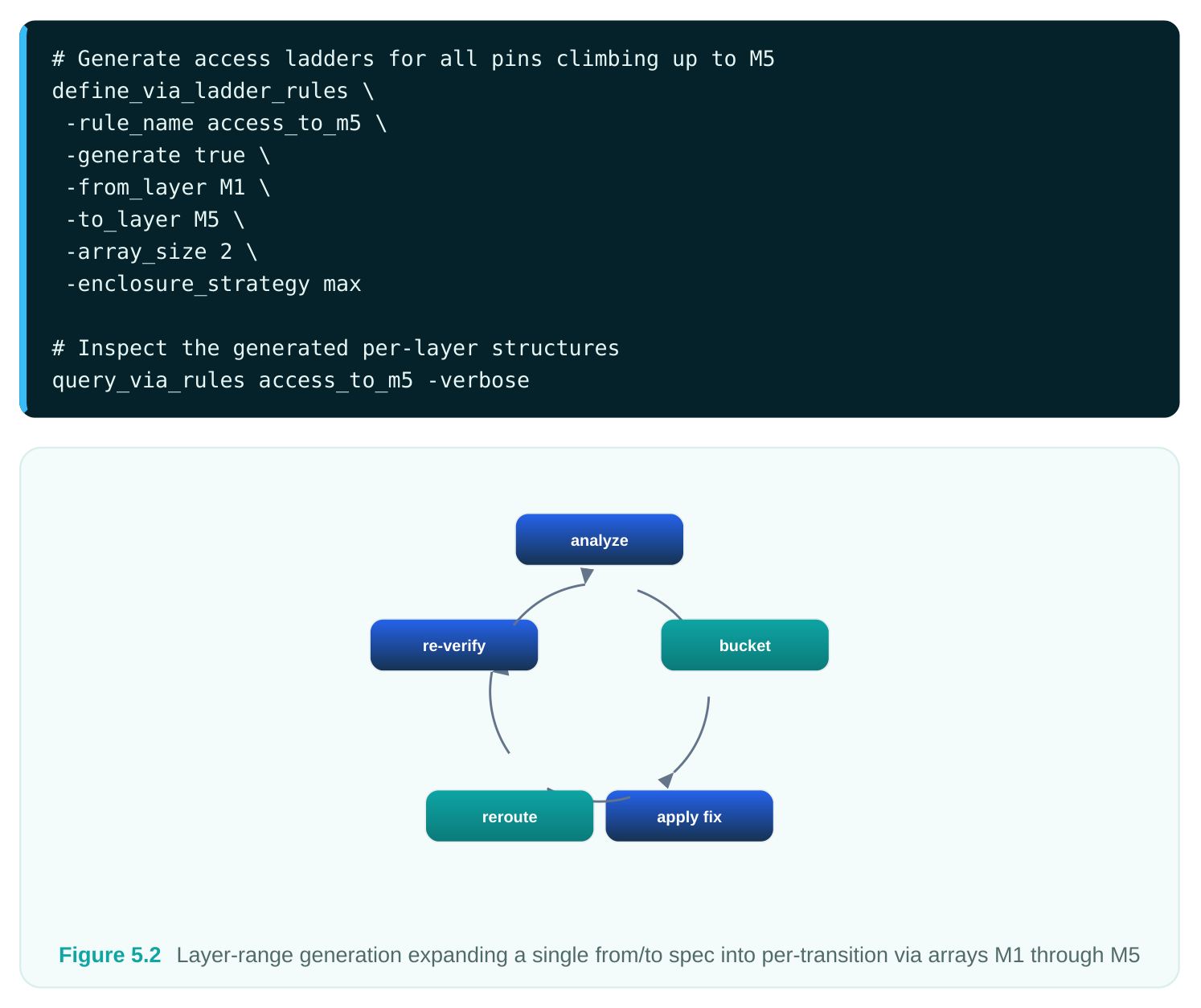
When you generate across a range, the tool selects appropriate via arrays for each transition based on the technology, applies the array size and enclosure strategy you asked for, and assembles them into a coherent stack. The -verbose read-back is your friend here — generation is convenient precisely because it hides detail, so you should always verify the expanded result rather than trusting the one-line command.
Electromigration Via Ladders
EM ladders are where the structure earns its keep. The whole point is current-carrying capacity, so the rule is tuned for parallel cuts and generous metal rather than for a tidy minimal footprint. You typically widen the via arrays, sometimes widen the connecting metal, and you tie the rule to nets or pins that you know carry high current.
# Define an EM-robust via ladder for high-current pins
define_via_ladder_rules \
-rule_name em_high_current \
-from_layer M1 \
-to_layer M6 \
-via_master {VIA12_3x3 VIA23_3x3 VIA34_2x2 VIA45_2x2 VIA56_2x2} \
-electromigration true \
-metal_strategy widen \
-taper_width 0.06
# Bind the EM rule to the strong-driver output pins via a constraint
set_via_ladder_constraint \
-rule em_high_current \
-pins [get_pins -of_objects [get_nets -hierarchical CLK_ROOT*] -filter
"direction==out"]
Notice the larger arrays at the bottom (3x3 near the pin, where current density is highest) and the - electromigration true flag, which tells the tool to treat the ladder as an EM structure and apply the corresponding checks and preferences. The -taper_width value brings us to the next topic, because tapering is the knob that decides how the ladder transitions from a wide, current-hungry base to the narrower upper-layer metal. The contrast between an access ladder and an EM ladder is worth tabulating, since interviewers love to probe whether you understand that they are tuned differently.
| Aspect | Access ladder | EM ladder |
|---|---|---|
| Primary goal | Router landing, escape ease | Current-density / EM margin |
| Via array size | Small (often 1x1 or 2x1) | Large, parallel cuts (2x2, 3x3) |
| Metal strategy | Minimal, follow the pin | Widened for capacity |
| Bound to | Pins on a layer, broadly | High-current nets / pins, selectively |
| Tapering | Often unnecessary | Important, base-to-top width control |
Controlling Connections and Tapering Width
Two further controls deserve attention because they are where ladders go wrong if you are careless. The first is connection control — governing how the ladder ties to the pin below it and to the routing above it. A ladder that is structurally beautiful but does not actually connect to the pin metal, or that lands somewhere the router cannot reach, is worse than no ladder at all. The rules let you constrain which pin shapes the ladder is allowed to sit on and how the top of the ladder presents itself to the router, so that the detail router sees a clean, legal target. The guiding principle: the ladder is a bridge, and a bridge with one unanchored end is a liability.
The second is tapering width. When an EM ladder starts wide at the bottom — wide metal, big via arrays — it cannot stay that wide all the way up; the upper layers have their own width rules, the tracks are narrower, and a fat ladder all the way to M6 would devour routing resources. Tapering lets the ladder shrink in a controlled, DRC-clean way as it climbs, so the base carries the current and the top is friendly to the router. The -taper_width parameter shown earlier sets the target metal width for the tapered upper portion; choosing it well is a balance between EM margin (which wants width) and routability (which wants compactness). EM via ladder — wide base, tapering up M6 M5 M4 M3 M2
M1 high-current pin at each step A practical note: tapering interacts with the layer span. A ladder that only climbs two layers has little room to taper meaningfully, while one spanning four or five layers can taper gradually and gracefully. If you find your tapering looks abrupt, the span is probably too short for the width delta you are asking for.
What insert_via_ladder Does — and Does Not Do
With rules defined and constraints bound, insert_via_ladder is the command that actually places the structures. Understanding its precise behavior is the single most interview-tested part of this topic, because its scope is narrower than people assume.
# Insert ladders according to all defined rules and constraints
insert_via_ladder
# Or restrict insertion to a specific rule
insert_via_ladder -rule em_high_current
# Or target an explicit set of pins
insert_via_ladder -pins [get_pins {U_drv/Z U_clkbuf/Z}]
Here is the behavior you need to have straight.
Where ladders are inserted. Ladders are placed at the target pins identified by your constraints (or by the explicit -pins argument), climbing the layer span defined by the matching rule. The command works pin by pin against the rules that apply. One ladder per target pin. The command inserts a single via ladder for each target pin. It does not stack multiple ladders on the same pin, and it does not try to build several competing structures and pick a winner. One pin, one ladder. If two rules could both apply to the same pin, you are responsible for the precedence — do not assume the tool will merge them. It does not remove existing ladders. This is the classic trap. insert_via_ladder is additive with respect to what is already there in the sense that it will not clean up or replace ladders from a previous run on its own. If you re-run after changing a rule, you can end up reasoning about a pin that already has a ladder. The safe methodology is to remove prior ladders explicitly before re-inserting when you have changed the rules, rather than expecting the insert command to reconcile old and new. It does not report insertion status. The command does not hand you a tidy pass/fail summary of which pins got ladders and which were skipped. It does the placement; it does not produce a verification report. So you cannot treat a clean command return as proof that every intended pin received a correct ladder. You have to verify independently — query the design, inspect the pins, check EM margins downstream — to confirm the ladders are where you expect and shaped the way you intended. Routing Flow
| Global | Track | Detail | Postroute |
|---|---|---|---|
| Route | Assignment | Route | Opt |
Figure 5.4 Insert_via_ladder flow showing constraints -> per-pin insertion -> single ladder per pin, with crossed-
out boxes for "removes old ladders" and "emits status report" That last pair of "does not" points is exactly why the read-back habit matters. The workflow is define, bind, insert, then verify yourself — not define, insert, and trust. Build your sign-off scripting around the assumption that you are the one checking the result.
A Realistic End-to-End Flow
Tying it together, here is how the pieces sequence in a typical block. Notice the explicit verification at the end, since the command will not do it for you.
# 1. Pull baseline structures from library/library-model data (already loaded with
the tech)
query_via_rules
# 2. Author a block-specific EM ladder
define_via_ladder_rules \
-rule_name em_high_current \
-from_layer M1 -to_layer M6 \
-via_master {VIA12_3x3 VIA23_3x3 VIA34_2x2 VIA45_2x2 VIA56_2x2} \
-electromigration true -metal_strategy widen -taper_width 0.06
# 3. Bind it to the high-current pins
set_via_ladder_constraint -rule em_high_current \
-pins [get_pins -of_objects [get_nets HVDD_SW*] -filter "direction==out"]
# 4. Insert
insert_via_ladder -rule em_high_current
# 5. Verify yourself -- the command reports nothing
query_via_rules em_high_current -verbose
# (follow with pin/EM queries in your own QA scripts)
Interview Q&A
Two reasons, and a strong answer names both. For pin access, a pre-placed ladder gives the router a robust, predictable structure to land on, which matters on advanced nodes where lower-layer pins are tiny and escape routes are scarce — it reduces marginal single-cut landings that become DRC or hotspot problems. For electromigration, a single via cut limits how much current a transition can carry; a ladder uses stacked via arrays with many parallel cuts so current splits across them and no single transition exceeds the EM limit. Same structure, two motivations, tuned differently for each.
Three sources: a Tcl script using define_via_ladder_rules , library/technology data in library-model format, or an external XML rule file. You use the Tcl path for hands-on, block-specific tuning — especially EM ladders you are iterating on. You use library-model/library definitions when the ladder geometry must align with sign-off assumptions the library team already validated. XML is the hand-off format for definitions generated upstream or shared between teams. Real flows usually mix them: baseline from library data, block-specific EM rules added by script.
settings? An access ladder optimizes for routability: small via arrays (often 1x1 or 2x1), minimal metal that follows the pin, applied broadly across pins on a layer, with little need for tapering. An EM ladder optimizes for current capacity: large parallel via arrays (2x2, 3x3, biggest near the pin where density is highest), widened metal, the -electromigration flag set, bound selectively to high-current nets, and
tapering controlled so the wide base carries current while the narrower top stays router-friendly. The structures look similar but the parameter choices are opposite in spirit.
It does not remove or replace existing ladders, it inserts only one ladder per target pin, and it does not produce an insertion-status report. This matters because re-running after a rule change can leave stale ladders in place unless you explicitly remove them first, and because a clean command return is not proof that every intended pin got a correct ladder. The disciplined workflow is define, bind, insert, then verify independently with your own queries — never assume the command reconciled old structures or self-reported success.
Key Takeaways
- A via ladder is a deliberate stacked column of vias and metal climbing from a pin through several layers; it serves pin access (a robust router landing) and EM robustness (parallel cuts that split high current) — the same structure, tuned differently.
- Rules describe what a good ladder looks like; constraints describe where to apply it. Keep them decoupled so a single tuned rule can be reused.
- Rules come from three sources — a Tcl script (
define_via_ladder_rules), library/library-model data, or an XML file — and real flows often combine library baselines with script-authored EM rules. - Use the generation flow to expand a single from/to spec into per-transition arrays over a layer range, but always read back the expanded result with
query_via_rules -verbose. - EM ladders use large bottom arrays, widened metal, the electromigration flag, and tapering to shrink gracefully toward the top so the base carries current while the top stays routable.
- Control connections so the ladder anchors cleanly to the pin below and presents a legal target above — a ladder with an unanchored end is worse than none.
insert_via_ladderplaces one ladder per target pin at the constrained pins. It does not remove existing ladders and does not report status — so remove stale ladders before re-running and verify the result yourself.
Comments
Leave a Reply