 ChipBuddy
← Home
ChipBuddy
← Home
Routing Secondary Power & Ground Pins
Routing Secondary Power and Ground Pins
When most engineers picture power and ground (PG) connectivity, they think of the big stuff: the toplevel rings, the strap mesh marching across the floorplan, and the follow-pin rails that thread under every standard-cell row. That infrastructure is built during power planning and stitched together long before the signal router ever wakes up. But there is a quieter category of PG connections that the signal router itself has to handle, one net at a time, almost as if they were ordinary signals. These are the secondary PG pins, and in modern low-power designs they are everywhere. Getting them connected correctly — and efficiently — is one of those tasks that separates a clean route from one that bleeds DRCs and timing surprises late in the flow. This chapter explains what secondary PG pins are, why the router treats them with a signal-like discipline instead of folding them into the mesh, how the routing tool (and the router engine underneath it) identifies and connects them, and how you control the effort spent on them through tool options. We will keep the multi-voltage and UPF context at a working altitude — enough to understand why these pins exist, without turning into a power-intent tutorial.
Primary versus Secondary PG: Two Different Jobs
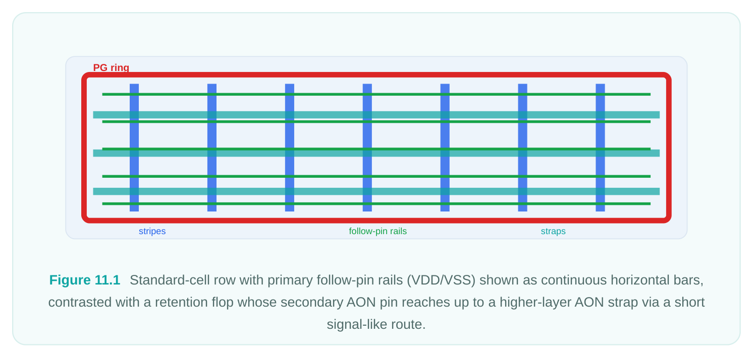
A primary PG rail carries the main current that switches the logic. It is the VDD/VSS that powers the bulk of your standard cells and macros. These rails are wide, redundant, and built as a structured grid because they need to deliver large, fast-changing currents with minimal IR drop and electromigration headroom. You do not route these one pin at a time — you plan a mesh and let every cell tap into the follow-pin rails by abutment. A secondary PG pin is a power or ground connection on a cell that is not its main switched supply. These pins are typically low-current and topologically isolated from the primary grid. Common examples include:
- N-well bias / body-bias pins on cells that support adaptive or reverse body biasing, where the well must be tied to a dedicated bias supply rather than the nominal VDD.
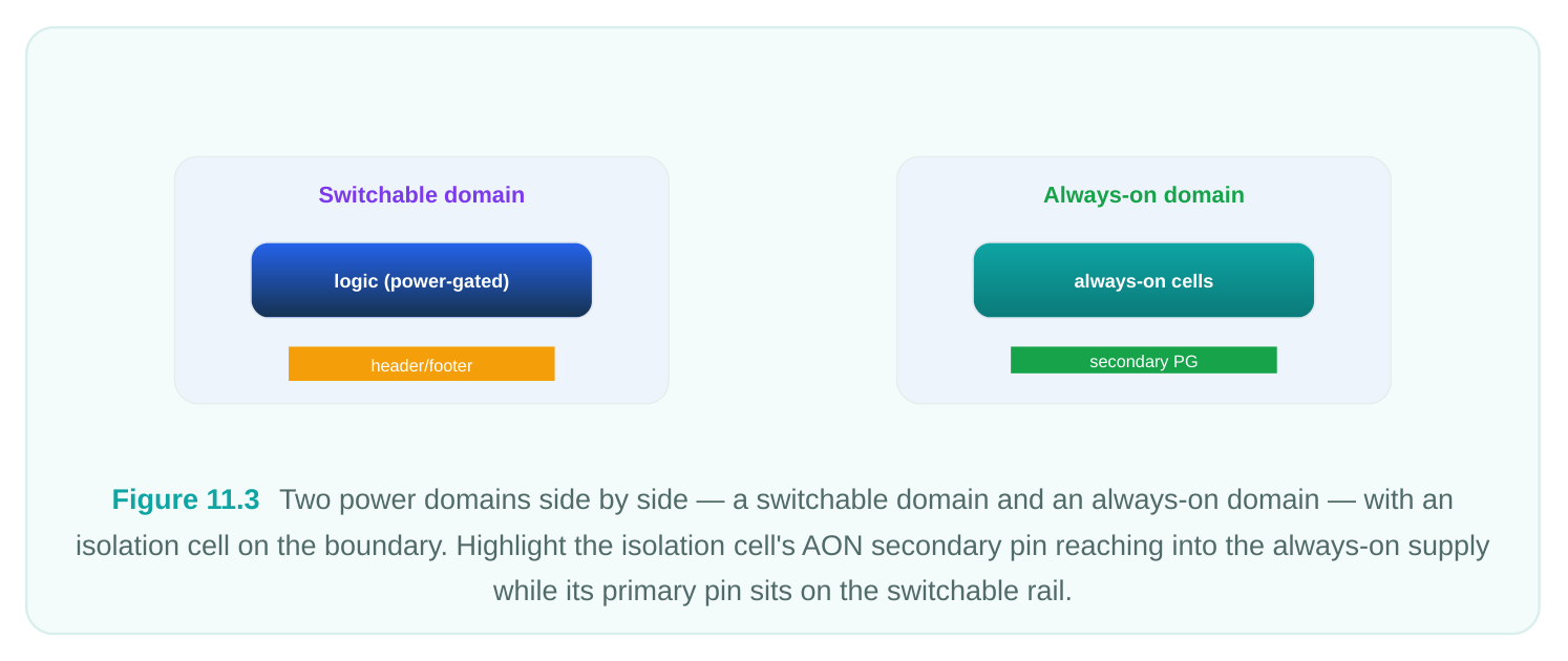
- Always-on (AON) supply pins on isolation cells, level shifters, and retention flops that must stay powered while the surrounding domain is shut down. The AON net is a real supply, but it is a separate net that does not align with the local follow-pin rail.
- Header/footer enable or backup-supply pins associated with power-gating structures, where a secondary supply feeds retention storage.
- Dual-rail pins on certain level shifters and isolation cells that legitimately straddle two voltage domains and therefore need two different supplies connected. The defining trait is the same in every case: the pin needs a specific net that is not the rail running through the cell row. The follow-pin rail gives you the primary supply for free by abutment; the secondary supply has to be fetched and connected explicitly.
| Attribute | Primary PG Rail | Secondary PG Pin |
|---|---|---|
| Current magnitude | High, fast switching | Low, mostly static |
| Construction phase | Power planning (pre-route) | Signal route stage |
| Connection method | Mesh, straps, follow-pins by abutment | Point-to-point, signal-like |
| Redundancy | Heavy (many vias, wide metal) | Minimal (a few vias suffice) |
| Net example | VDD, VSS | VDDG (bias), VDD_AON, VBB |
| Who builds it | create_power_* / power plan | the router / route_net_group |
Why Signal-Like Routing, Not the Mesh
It is tempting to ask: if a secondary PG pin needs a supply, why not just extend the mesh to cover it? The answer comes down to geometry and locality. Secondary pins are scattered — a retention flop here, an isolation cell there — and the nets they need (AON, bias) usually exist as relatively sparse straps on a higher metal layer, not as a dense follow-pin grid at the cell level. Building a full mesh down to every one of these pins would waste enormous routing resource on layers that signals desperately need, and it would do so to carry currents that are tiny. Instead, the router treats the secondary PG net like a signal net with a small fan-out: find the nearest available source geometry (a strap, a ring segment, an existing piece of the secondary net), and drop a short, legal connection from the pin up to it. This is exactly the kind of localized, congestion-aware, DRC-clean point-to-point routing the signal engine is designed for. It uses the same track structure, the same via rules, and the same shape-based DRC engine as ordinary nets. The difference is mostly bookkeeping: the router knows these are PG nets, so it can apply different width or via preferences and it knows it must avoid shorting them against the primary rails they happen to cross. Because the connections are short and low-current, the router does not need to lavish redundancy on them. The key control, as we will see, is how many connection points to make per pin — enough for reliability, not so many that you burn area and runtime.
Identifying Secondary PG Pins
Before the router can connect anything, the design has to declare which pins are secondary PG and which net each one belongs to. This information flows from two main sources:
- 1. The cell library (Liberty / LEF). A cell's PG pins are described with attributes that mark them as
primary_power , primary_ground , backup_power , backup_ground , pwell , nwell , and so on. Anything that is not the primary pair is, by definition, a secondary PG pin from the router's point of view.
- 2. The power intent (UPF). The UPF defines the supply nets and which logical supply each pin maps
to. When you connect_supply_net for an always-on net, or define isolation and retention strategies, the tool resolves which physical net the secondary pin must reach.
In the routing tool you can interrogate this before routing so there are no surprises. A quick audit confirms that every secondary pin has a real net to connect to and that the source geometry for that net actually exists nearby.
# Survey secondary PG pins and the nets they must reach
set sec_pins [get_pins -physical_context \
-filter "is_pg_pin == true && pg_type =~ *backup* || pg_type =~ *bias*"]
foreach_in_collection p $sec_pins {
set net [get_attribute $p net.name]
set cell [get_attribute $p cell.name]
puts "Secondary PG pin [get_attribute $p name] on $cell -> net $net"
}
# Confirm the secondary supply nets actually have routable source geometry
report_pg_nets -nets {VDD_AON VBB} -connectivity
If a secondary net has no straps, rings, or pre-routes anywhere near a pin, the router has nothing to connect to — it will leave the pin open. That failure mode is almost always a power-planning gap, not a router bug. Catch it here.
Controlling the Number of Secondary PG Pin Connections
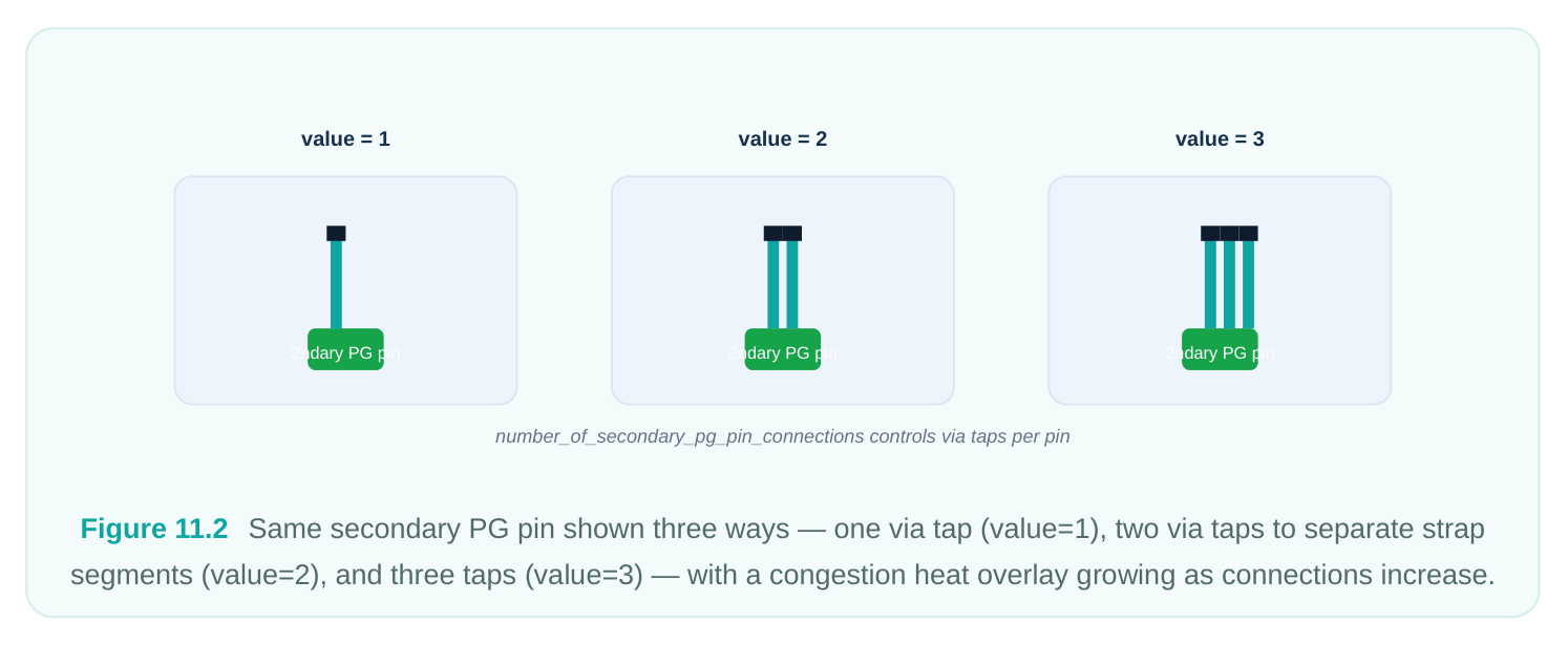
The headline knob for this whole topic is an tool option that tells the router how many connection points to create per secondary PG pin:
# Default is typically 1; raise it for reliability-critical secondary supplies
set_tool_option -name common.number_of_secondary_pg_pin_connections \
-value 2
The semantics are straightforward: the value sets the target number of distinct attachments the router will try to make from each secondary PG pin to its supply source. The reasoning behind tuning it:
- Value of 1 (default-ish). One good connection per pin. Minimal resource, fastest. Appropriate for low-current bias and well-tie pins where a single robust via stack is plenty.
- Value of 2 or more. Redundant connections for pins that are more reliability-sensitive — an always-on net feeding retention storage, for example, where losing the tie means losing state. The extra connection buys via redundancy and EM margin at the cost of a little area and runtime. A word of caution: raising this number multiplies routing demand on exactly the upper layers where your secondary straps live. On a congested design, pushing it too high can create localized hot spots and even leave fewer pins fully connected because the router runs out of room. Treat it as a reliability dial, not a "more is better" setting, and revisit it if you see secondary-PG congestion in the congestion map.
| Option | Connections per | ||
|---|---|---|---|
| Use when | Trade-off | ||
| value | pin | ||
| 1 | Single attachment | Bias / well-tie pins, low current | Lightest on resource and |
runtime
| 2 | Redundant | AON nets feeding retention, EM- | More vias, more upper-layer |
|---|---|---|---|
| attachment | sensitive | demand | |
| 3+ | Heavily redundant | Very high reliability requirement, rare | Risk of congestion, diminishing returns |
How the Router Connects Them, and When
The actual connection work is part of the group/PG routing pass that the signal router orchestrates. In the routing tool the relevant command is route_net_group , which lets you scope a routing operation to a particular class of objects — including PG pins — rather than the whole design. A typical invocation that focuses the engine on secondary PG connectivity looks like this:
# Stage 1: make sure the option is set before the pass runs
set_tool_option -name common.number_of_secondary_pg_pin_connections \
-value 2
# Stage 2: route the secondary PG pins as a dedicated group operation
route_net_group -pg_pin_connections true \
-nets {VDD_AON VBB VDDG} \
-reuse_existing_global_route false
# Stage 3: follow with normal detail routing for the signal nets
auto_route
Ordering relative to signal routing matters. The standard practice is to resolve secondary PG connections before or interleaved with the bulk of signal detail routing, not after. There are two reasons. First, these connections often want clean access to upper-layer straps; if you let signals fill
those tracks first, the PG taps get squeezed. Second, once the secondary PG geometry is committed, the signal router can see it as a hard obstacle and route around it cleanly — whereas doing PG last forces the router to rip up and reshuffle already-legal signal wires. In a typical the routing tool auto_route flow, PG pin handling is integrated so that the engine reserves access and lays down these taps as part of the same converged solve, but when you drive the steps manually with
route_net_group , you control the sequence explicitly and should front-load the PG work. The router applies the same DRC engine throughout, so a secondary PG tap that crosses a primary rail is checked for spacing and shorts exactly like any other shape. The PG-awareness ensures it never accidentally merges a secondary net (say, VDD_AON) into the primary VDD it physically passes over — net identity is preserved end to end.
The Low-Power / Multi-Voltage Context
Secondary PG routing only becomes a major topic because of low-power design. In a single-voltage chip with no power gating and no body biasing, nearly every cell taps the primary rail by abutment and you are done. The moment you introduce multiple voltage domains, switchable power, retention, and adaptive biasing, you create a population of cells that legitimately need a second supply that the local rail cannot provide. UPF is where this intent is captured. At a high level:
- Power domains partition the design; each has its own primary supply. Cells on the boundary need to talk across domains.
- Isolation cells clamp signals leaving a domain that may be shut off; they typically need an always- on supply so they keep clamping even when the source domain is dark.
- Level shifters translate between voltage domains and may carry two supply rails — both of which must be connected.
- Retention registers keep state through a power-down using a backup/AON supply on a secondary pin.
- Body-bias schemes route a separate bias net to well-tie pins to shift threshold voltage dynamically. The router does not interpret UPF directly during the tap-down — by the time you route, the power intent has already been resolved into concrete supply nets and pin-to-net associations. But understanding the UPF lineage tells you why a given pin needs the net it needs, and it tells you which secondary nets are reliability-critical (retention AON) versus merely functional (a static well bias). That judgment is what guides your
number_of_secondary_pg_pin_connectionschoice.
Interview Q&A
router handle the secondary ones? A primary PG pin carries the cell's main switched supply and is connected through the planned mesh and follow-pin rails by abutment. A secondary PG pin needs a different net — an always-on supply, a body-bias net, a backup supply — that does not run through the cell row. Because these pins are sparse, low-current, and need point-to-point access to higher-layer straps, the signal router connects them with localized, DRC-clean, signal-like routing rather than extending the power mesh, which would waste routing resource for negligible current.
and what drives the choice? You set common.number_of_secondary_pg_pin_connections . A value of 1 makes a single attachment, which is fine for low-current bias and well-tie pins. Raising it to 2 or more creates redundant taps for reliability-critical nets such as an always-on supply feeding retention storage, buying via redundancy and EM margin. The trade-off is that more connections consume upper-layer routing resource where the secondary straps live, so on a congested design over-driving the value can create hot spots and actually leave pins unconnected.
routing rather than after? Secondary PG taps want clean access to upper-layer straps. If signals occupy those tracks first, the taps get squeezed or cannot complete. Front-loading the PG work also lets the signal router treat the committed PG geometry as a fixed obstacle and route cleanly around it, avoiding rip-up and reroute of already-legal signal wires. In an integrated auto_route flow the engine reserves access automatically, but when you stage it manually with route_net_group you should sequence the PG connections first.
and how do you diagnose it? The most common cause is not a router defect but a power-planning gap: the secondary supply net has no straps, rings, or pre-routes near the pin, so there is nothing to connect to. Diagnose it by querying the pin's target net with get_attribute and running
report_pg_nets -connectivity on that net to confirm routable source geometry exists in the vicinity.If the source is missing, fix the power plan; if it exists but the pin is still open, check for local
congestion or an over-aggressive connection count, and inspect the congestion map on the secondary straps' layers.
Key Takeaways
- Secondary PG pins are non-primary supply connections — always-on, body-bias, backup, and dual-rail pins — that the signal router connects point-to-point, not the power mesh.
- They get signal-like routing because they are sparse and low-current; meshing down to them would waste upper-layer resource for negligible benefit.
- Identification flows from library PG-pin attributes and UPF supply intent; audit the target nets before routing to confirm routable source geometry exists.
set_tool_option -name common.number_of_secondary_pg_pin_connectionsis the primary reliability dial: 1 for low-current pins, 2+ for retention/AON nets, mindful of congestion.- Use
route_net_groupwith PG-pin scope to handle these connections, and sequence them before or with signal detail routing so they get clean strap access. - The whole topic exists because of low-power, multi-voltage design; understanding the UPF lineage tells you which secondary nets are reliability-critical and therefore worth extra connections.
Comments
Leave a Reply