 ChipBuddy
← Home
ChipBuddy
← Home
Defining Vias
Defining Vias
If wires are the highways of a chip, then vias are the on-ramps and overpasses that let a net climb from one metal layer to the next. Routing in any modern flow is fundamentally a three-dimensional problem: the router lays horizontal segments on one layer, vertical segments on the adjacent layer, and stitches them together with vias at every layer transition. A net that travels from a standard-cell pin on M1 up to a global signal track on M6 may pass through five or six distinct via stacks before it terminates. Multiply that by tens of millions of nets and you begin to appreciate why the router's understanding of vias is not a footnote — it is one of the central pillars of routability, timing, yield, and electromigration robustness. This chapter is about how the router learns what a legal via looks like. The technology file ships with via definitions and via rules, but as an engineer you will frequently create, query, and constrain vias yourself. Getting this wrong is a classic source of frustration: the router may detour wildly, fail to connect pins, insert resistive single-cut vias where double-cuts were intended, or flag a flood of design rule violations that all trace back to a single malformed via definition. We will work through what vias are made of, the difference between simple and custom vias, how to author them with define_via , how to interrogate the library with query_via_rules , and how to drive concurrent redundant-via insertion during detail routing.
| M6 | vertical |
|---|---|
| M5 | horizontal |
| M4 | vertical |
| M3 | horizontal |
| M2 | vertical |
| M1 | horizontal |
alternating preferred directions, stitched by vias (dark squares)
Figure 4.1 Cross-section of a multi-layer routing stack showing M1-M2-M3 wires connected by via stacks, with cut
layers VIA1/VIA2 highlighted between metals
What a via actually is, and why the router cares
Physically, a via is a tungsten or copper plug that punches through the inter-layer dielectric to electrically join two metal layers. In the layout database, a via is described by three ingredients: a cut layer (the via layer itself, e.g. VIA1 between M1 and M2), a bottom metal enclosure, and a top metal enclosure. The cut is the conductive hole; the enclosures are the rectangles of metal on each adjacent layer that overlap the cut so that even with mask misalignment the cut is fully landed on metal. A via is therefore not a single shape — it is a small assembly of three (or more) shapes that must satisfy a web of design rules simultaneously. The router cares about each of these dimensions for distinct reasons:
- Cut layer and cut size determine the via's resistance and current-carrying capacity. A single small cut is resistive and EM-weak; arrays of cuts are robust.
- Enclosure rules dictate how much metal must surround the cut, and these rules are frequently asymmetric — the foundry may demand more enclosure along one axis than the other, which forces the router to think about via orientation.
- Via spacing controls how close two cuts may be placed, which constrains how densely the router can pack vias in a congested region and whether redundant vias will even fit. Because every one of these interacts with the metal pitch above and below, a via that is legal in isolation can still be illegal in context. The router's via models exist so it can reason about all of this at the moment it drops a via, rather than discovering the violation afterward.
Simple vias versus custom vias
Tools draw a practical distinction between two flavors of via. A simple via is the workhorse. It is a regularly structured via — a single cut, or a clean rectangular array of identical cuts — whose geometry is fully described by a handful of parameters: cut size, the number of rows and columns of cuts, cut-to-cut spacing, and the bottom/top enclosure values. The
router can generate simple vias on the fly and adjust their array dimensions to satisfy EM or yield targets. Because they are parameterized rather than hand-drawn, they are flexible and the engine loves them. A custom via (sometimes called a fixed or generated-master via) is an explicit, frozen piece of geometry. You reach for one when the regular parameterization cannot express what the foundry requires: a bar-shaped cut, a non-uniform array, an offset enclosure to dodge a neighboring shape, a via that includes a special metal-fill notch, or a vendor-mandated structure that simply does not fit the simple-via template. Custom vias buy you total control at the cost of flexibility — the router places them as-is and cannot reshape them.
| Aspect | Simple via | Custom via |
|---|---|---|
| Definition style | Parameterized (cut size, rows/cols, | Explicit fixed geometry / generated master |
spacing, enclosure)
| Router | High — can resize arrays, choose | Low — placed exactly as drawn |
|---|---|---|
| flexibility | orientation | |
| Typical use | Default signal/clock connections, | Bar cuts, irregular arrays, special structures |
redundant via arrays
| Maintenance | Easy to tweak by changing parameters | Must redraw to change |
|---|---|---|
| When to prefer | The common case; trust it by default | Only when simple parameterization can't |
express the rule The guiding principle: prefer simple vias unless a foundry rule or a specific structural need forces you into a custom one. Custom vias scattered through a design reduce the router's freedom and can hurt routability in congested blocks.
Creating via definitions with define_via
A via definition tells the database the recipe for a particular via master. In a the routing tool / the routerstyle flow you author one with define_via , naming the cut layer and the two metal layers it bridges, and supplying the cut and enclosure geometry. The example below defines a single-cut VIA1 between M1 and M2 with explicit enclosures, then a 2x2 array variant for higher current paths.
# Single-cut via definition: VIA1 bridging M1 (bottom) and M2 (top)
define_via my_VIA1_1cut \
-cut_layer VIA1 \
-lower_layer M1 \
-upper_layer M2 \
-cut_size {0.040 0.040} \
-lower_enclosure {0.005 0.020} \
-upper_enclosure {0.020 0.005} \
-rows 1 -columns 1
# 2x2 redundant array for EM-critical and high-fanout nets
define_via my_VIA1_2x2 \
-cut_layer VIA1 \
-lower_layer M1 \
-upper_layer M2 \
-cut_size {0.040 0.040} \
-cut_spacing {0.046 0.046} \
-lower_enclosure {0.005 0.020} \
-upper_enclosure {0.020 0.005} \
-rows 2 -columns 2
Notice the asymmetric enclosures. The lower enclosure {0.005 0.020} means 4 nm in X and 22 nm in Y; the upper is the reverse. This encodes the common foundry pattern where each metal layer must extend the via further along its own preferred routing direction. When the router places this via it must respect that asymmetry, which is precisely why orientation matters — rotating the via 90 degrees swaps which axis gets the generous enclosure, and only one orientation may actually be legal against the adjacent wire. When you build redundant arrays you also have to supply cut spacing. Here -cut_spacing {0.046 0.046} sets the center-to-center or edge-to-edge cut separation (consult your tool's convention) so the two-by-two grid of cuts clears the minimum cut-to-cut rule. If you under-spec this, the array master itself is illegal before it is ever placed. For a custom via you bypass the parameterization and register fixed geometry instead, typically by referencing pre-drawn shapes or a generated master:
# Custom via built from explicit, foundry-mandated geometry
define_via special_VIA3_bar \
-cut_layer VIA3 \
-lower_layer M3 \
-upper_layer M4 \
-is_custom true \
-geometry_from_cell BAR_VIA3_MASTER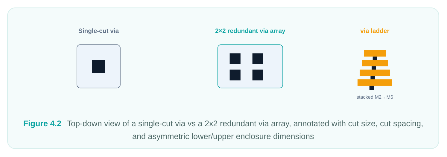
Via rules and querying with query_via_rules
A single via definition is one recipe. A via rule is the higher-level policy that tells the router which via definitions it is allowed to generate between a given pair of layers, and what parameters it may sweep. Via rules are what let the router automatically pick, say, a 1x1 via on a lightly loaded net but a 1x2 array where it needs more robustness — all from a governed set of legal masters. The technology library populates these rules; you query and occasionally extend them. To inspect what the router has to work with, use query_via_rules . This is your first diagnostic whenever connections behave oddly.
# List every via rule the technology has defined
query_via_rules *
# Narrow to rules touching a specific cut layer
query_via_rules -filter {cut_layer == VIA2}
# Dump the attributes of one rule to see its layers and allowed array range
report_attributes [query_via_rules my_VIA1_rule]
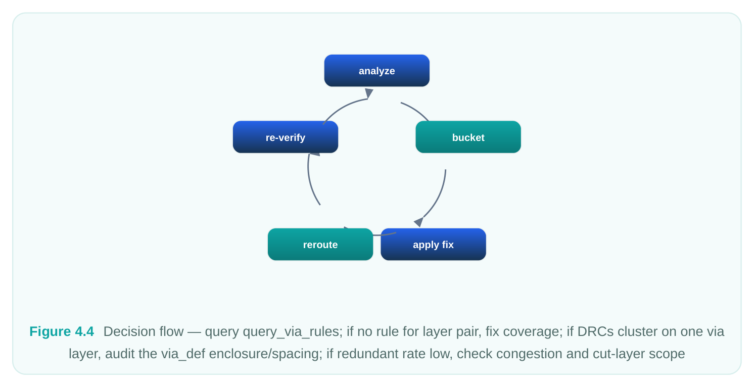
If query_via_rules returns nothing for a layer pair you expect to route across, that is a red flag — the router has no sanctioned way to transition between those layers, and you will see open nets or bizarre detours. The table below maps common queries to what they tell you.
| Command | What it answers |
|---|---|
| query_via_rules * | Does every adjacent layer pair have at least one rule? |
| query_via_rules -filter {cut_layer == | Which rules govern transitions through cut VIAn? |
VIAn}
report_attributes [query_via_rules What lower/upper layers, cut size, and array bounds does| <name>] | this rule permit? |
|---|---|
| get_via_defs * | Which concrete via masters exist for the router to |
instantiate?
A healthy library has, for every metal-to-metal transition the design needs, a via rule pointing at one or more valid via definitions, with enclosure and spacing values consistent with the metal layers' own rules.
Redundant vias for yield and electromigration
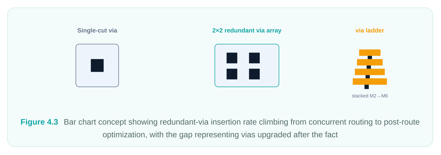
A single via cut is a single point of failure. If that one cut is malformed by a random manufacturing defect — a void, a partial etch, an electromigration-driven open — the net breaks. A redundant via (also called a double via or via array) places two or more cuts in parallel so the connection survives the loss of any one cut. This is one of the highest-leverage yield techniques available in routing, and it simultaneously improves electromigration headroom because the current divides across multiple cuts, lowering the current density through each. There are two moments to insert redundant vias:
- 1. Concurrently, during detail routing. The router is told to prefer multi-cut vias as it routes, so
redundancy is woven in from the start. This produces the cleanest result because the router accounts for the array footprint while it still has freedom to choose tracks.
- 2. As a post-route optimization step. After routing completes, a dedicated pass walks the design
and upgrades single-cut vias to arrays wherever space permits, without rerouting. This catches whatever concurrent insertion could not fit. In practice you use both: concurrent insertion to get most of the way, then a post-route sweep to push the conversion rate higher. The metric you watch is the redundant via rate — the fraction of vias that ended up multi-cut. Mature flows routinely target the high nineties percent.
You enable concurrent redundant-via behavior through tool options before invoking detail routing. The exact option names vary by tool version; the pattern looks like this:
# Turn on concurrent redundant (double) via insertion during detail routing
set_tool_option -name detail.insert_redundant_via -value true
# Optionally bias the effort/aggressiveness of the conversion
set_tool_option -name detail.redundant_via_effort_level -value high
# Restrict redundant vias to specific cut layers if upper layers are too tight
set_tool_option -name detail.redundant_via_cut_layers -value {VIA1 VIA2 VIA3}
# Run detail routing; redundancy is now considered as part of routing
detail_route
# Post-route top-up pass for vias that concurrent insertion could not convert
postroute_opt -optimize_redundant_via
A few judgments accompany these knobs. Higher effort yields a better redundant rate but costs runtime and can add congestion, since arrays consume more area than single cuts. On the densest upper layers you may deliberately exclude a cut layer from redundancy because the wider array simply will not fit alongside neighboring tracks. And critical nets — clock spines, power-sensitive signals, EM-flagged nets — often warrant a non-default rule that mandates redundancy or even a minimum array size, overriding the global setting.
Cut layers, enclosure, and via spacing — the rules that bind
Three families of rules govern whether a via is legal, and the router enforces all of them as it places vias. Cut layer rules concern the via cut itself: the minimum and maximum cut size, and for arrays the legal number of rows and columns. Some advanced nodes additionally restrict which cut shapes or sizes may appear on a given via layer, so a cut that is fine on VIA1 might be disallowed on VIA5. Enclosure rules require the surrounding metal to overlap the cut by a minimum amount on each layer. As we saw, these are commonly asymmetric and direction-dependent, which is the root cause of via orientation constraints. A via oriented so that its narrow enclosure faces a wide wire is legal; rotate it and the narrow enclosure may now violate the adjacent metal's spacing, making only one orientation routable in that spot. The router evaluates both candidate orientations and picks a legal one — but only if your via definition's enclosure values are correct to begin with. Via (cut) spacing rules set the minimum separation between two cuts, whether they belong to the same array or to two different vias placed near each other. This is what limits how tightly redundant arrays can pack and how close adjacent layer transitions may sit. Spacing rules at advanced nodes become genuinely intricate — same-net versus different-net spacing, parallel-run-length dependence, and more — and they are treated in depth in the dedicated rules chapter. For via definition purposes, the key point is that your -cut_spacing in an array master must clear the minimum cut spacing, or the master is born illegal.
| Rule family | Governs | Router consequence if violated |
|---|---|---|
| Cut layer rules | Cut size, array row/column counts | Illegal cut; via rejected |
| Enclosure rules | Metal overlap of cut (often asymmetric) | Orientation forced or via unusable; DRC errors |
| Via spacing rules | Cut-to-cut separation | Redundant arrays won't fit; cut-spacing DRCs |
Common pitfalls
The failure modes around vias are remarkably consistent across designs. The most common is a missing or incomplete via rule for a layer pair. The router needs a sanctioned path from layer N to layer N+1; if query_via_rules shows none, nets that must cross that boundary will not connect, and you will chase phantom open-net errors that have nothing to do with congestion. Always confirm full coverage across the layer stack before a big route. A close second is an invalid via definition — enclosure or spacing values that contradict the technology's own rules. Such a via passes define_via (the command does not always validate against the full rule deck) but then generates a storm of DRC violations the moment it is placed, or is silently never chosen, leaving the router to fall back on a worse master. When a particular via layer lights up with violations, suspect the definition itself, not the routing. Orientation mistakes follow from asymmetric enclosures: if both the bottom and top enclosure are wrongly specified as symmetric, the router may place vias that look fine in isolation but clash with the directional metal rules, again surfacing as DRCs concentrated on one via layer. Finally, over-aggressive redundant-via settings can backfire: pushing high effort on a congested upper layer where arrays cannot fit wastes runtime, inflates congestion, and barely moves the redundant rate. The fix is to scope redundancy to the layers where it pays and accept single cuts where geometry forbids arrays.
Interview Q&A
each? A via comprises a cut layer (the conductive hole), a lower-metal enclosure, and an upper-metal enclosure. The cut size and array count set resistance and EM capacity; the enclosures guarantee the cut lands on metal even under mask misalignment and, because they are often asymmetric, they impose orientation constraints; the cut spacing bounds how densely cuts and arrays can pack. The router reasons about all three together when it drops a via so that the result is legal in context, not just in isolation.
for the common case — it lets the router resize arrays and choose orientation freely, which is best for routability. Reach for a custom via only when the foundry requires a structure the simple template cannot express: a bar-shaped cut, a non-uniform or offset array, an enclosure shaped to dodge a neighbor, or a vendor-fixed master. Custom vias trade flexibility for control, so scatter them sparingly.
(multi-cut) vias are inserted concurrently during detail routing — by enabling an tool option so the router prefers arrays while it still has track freedom — and again in a post-route optimization pass that upgrades remaining single cuts where space allows. Using both maximizes coverage. You track the redundant via rate (fraction of vias that became multi-cut), typically targeting the high nineties, balancing it against congestion and runtime, and often forcing redundancy on EM-critical and clock nets.
via standpoint? First run query_via_rules filtered to the VIA4 cut layer (or the M4/M5 pair). If no rule exists, the router has no legal transition and you must add or restore a via rule pointing at a valid via definition. If a rule does exist, dump its attributes with report_attributes and confirm the via definition's enclosure and spacing are consistent with the M4/M5 metal rules — an invalid definition can be silently skipped, producing the same open-net symptom. The investigation always starts at the rule/definition level, not at congestion.
Key Takeaways
- A via is a three-part assembly — cut layer, lower enclosure, upper enclosure — and the router evaluates all three plus spacing every time it places one.
- Prefer simple, parameterized vias for flexibility; use custom fixed-geometry vias only when a foundry rule cannot be expressed otherwise.
- Author masters with
define_viaand verify the library withquery_via_rules; every layer pair the design crosses must have a via rule pointing at a valid definition. - Asymmetric enclosure rules drive via orientation — only one rotation may be legal against a given wire, so enclosure values must be correct or DRCs will cluster on that via layer.
- Redundant (multi-cut) vias boost yield and EM headroom; insert them concurrently during detail routing with
set_tool_option, then top up with a post-route pass, and track the redundant via rate. - Most via headaches trace to a missing via rule or an invalid via definition — debug from
query_via_rulesoutward before blaming congestion.
Comments
Leave a Reply