 ChipBuddy
← Home
ChipBuddy
← Home
Routing Constraints
Routing Constraints
Routing is rarely a free-for-all where the router simply connects pins with the thinnest legal wire. Real designs impose a layer of intent on top of the basic design rules: clock nets must be shielded and robust, critical timing paths want low-resistance wiring, certain regions of the floorplan must be kept clear or reserved, and advanced nodes demand that every wire and via respect multi-patterning color rules. All of these intentions are expressed to the routing tool (and the router engine underneath it) through routing constraints. This chapter walks through the major categories: nondefault routing rules, minimum geometry rules, routing guides, routing corridors, mask/color constraints, and the directional and on-grid constraints that keep the router honest. Mastering these is what separates an engineer who can run a route from one who can engineer a route.
Nondefault Routing Rules (NDR)
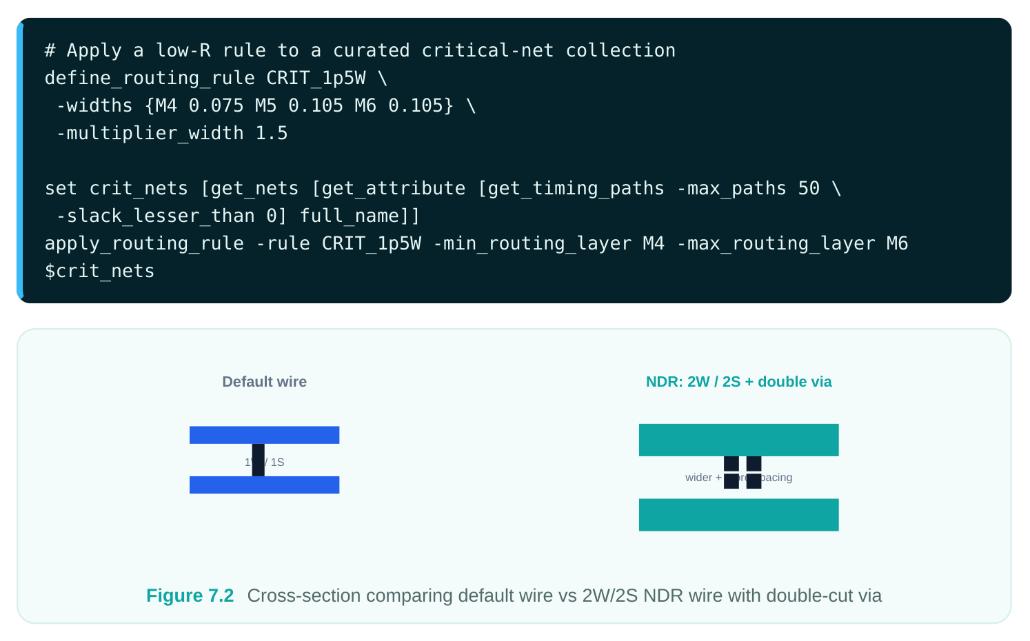
A nondefault routing rule is a named recipe that tells the router to build wires and vias differently from the default technology rule. The "default" rule is whatever the LEF/tech file declares as minimum width and minimum spacing for each layer. An NDR overrides that with some combination of wider wires, extra spacing, and multiple-cut (redundant) vias. You apply the rule selectively — to a clock tree, a handful of critical signals, or a class of nets — so the cost in routing resources is paid only where it buys something.
Why NDRs Matter
Three motivations dominate. First, resistance: a wider wire has lower per-unit resistance, which shrinks RC delay on long nets and is the standard tactic for high-fanout clock spines. Second, signal integrity: extra spacing pulls aggressors away from a victim net, reducing coupling capacitance and crosstalk-induced delay and noise. Third, reliability and yield: forcing double-cut or multiple-cut vias removes the single-via failure mode that dominates via electromigration and open-defect statistics. A clock NDR often combines all three — 2x width, 2x spacing, and double vias.
Creating and Applying an NDR
The rule is created once, then attached to nets. In the routing tool the command is define_routing_rule , and the attachment is done with apply_routing_rule .
# Define a 2W/2S clock rule with redundant vias on M3-M6
define_routing_rule CLK_2W2S \
-widths {M3 0.10 M4 0.10 M5 0.14 M6 0.14} \
-spacings {M3 0.10 M4 0.10 M5 0.14 M6 0.14} \
-multiplier_width 2 \
-multiplier_spacing 2 \
-via_cuts {VIA34 2 VIA45 2 VIA56 2}
# Attach the rule to every clock net, including taper at the leaf
apply_routing_rule -rule CLK_2W2S \
-min_routing_layer M3 -max_routing_layer M6 \
[get_nets -hierarchical -filter "net_type==clock"]
Two practical notes. The router will normally taper an NDR net back to default width near pins so it can actually land on the cell access points — that taper is allowed and expected. And the layer range you give to apply_routing_rule interacts with the rule's own width/spacing table; if a layer has no entry, the default for that layer applies. It is worth pausing on the cost side of NDRs, because interviewers love to probe whether a candidate understands the trade-off rather than just the syntax. A 2W/2S clock rule does not merely use twice the metal — it can consume roughly four times the routing area of a default net once you account for both the wider wire and the wider keep-away on each side. On a layer that is already 88% utilized, blanket-
applying a wide rule is a recipe for congestion and detour. The right instinct is to scope NDRs to the nets that genuinely move the needle: the clock distribution, the dozen worst setup paths, and the handful of nets that are SI-critical. Everything else routes default. A second subtlety is layer choice. Wide rules belong on the upper, thicker metals where the extra width buys the most resistance reduction per track consumed; forcing a wide rule onto M1/M2 mostly just destroys local routability. That is why most clock and critical NDRs specify a -min_routing_layer that pushes the net up off the lowest metals.
Assigning NDRs to Different Net Classes
The same machinery serves several use cases, each with a different rule:
| Net class | Typical NDR intent | Why |
|---|---|---|
| Clock nets | 2x width, 2x spacing, double vias | Skew/insertion-delay control, SI |
immunity, EM
| Critical signal nets | 1.5x–2x width, default spacing | Reduce RC delay on setup-limited paths |
|---|---|---|
| High-fanout / long nets | Wider wire, upper layers only | Lower resistance over distance |
| Sensitive analog/sense | Default width, 2x–3x spacing + nets | Isolate from digital aggressors shielding |
| Power-aware signal nets | Multi-cut vias only | Reliability without resource bloat |
For critical timing nets, a common flow is to let the optimizer identify the worst paths and then assign an NDR to just those nets before a final route:
Minimum Geometry Rules
NDRs express "do better than default," but there is a separate family of constraints that set hard floors on geometry independent of any per-net rule. These are the minimum width, minimum spacing, and minimum via-spacing rules. Some come straight from the technology file; others you tighten deliberately for a block or a region.
Minimum Wire Width
The minimum wire width is the narrowest legal metal on a layer. The tech file sets the absolute floor, but you may raise the effective minimum for a region or a net class — for example forcing all routing on a noisy power-domain boundary to be at least 1.5x the technology minimum. Raising minimum width trades routing density for resistance and reliability.
Minimum Wire Spacing
Minimum spacing is the smallest allowed edge-to-edge gap between two shapes on the same layer. Beyond the flat tech minimum, modern nodes carry width-dependent and parallel-run-length- dependent spacing tables: the wider a wire and the longer two wires run side by side, the more spacing the rules demand. The router consults these tables continuously, but you can also impose a stricter design-level minimum to buy crosstalk margin.
Minimum Via Spacing
Via spacing controls how close two via cuts (or via arrays) may sit. Tight via spacing helps pin access and routability; loose via spacing improves manufacturability and reduces cut-to-cut bridging risk, which matters a great deal at advanced nodes. Multi-cut vias from an NDR interact directly with this rule — a double via needs room.
| Rule type | Sets the floor on | Tightening it helps | Loosening it helps |
|---|---|---|---|
| Min wire width | Narrowest metal | Density | Resistance, EM, yield |
| Min wire spacing | Same-layer edge gap | Density | Crosstalk margin, yield |
| Min via spacing | Cut-to-cut distance | Pin access, density | Manufacturability, EM |
The mental model: tighter geometry rules favor area and routability; looser ones favor electrical quality and yield. Routing constraints let you dial the balance where the design needs it.
How These Interact with NDRs and the Router
A frequent point of confusion is the difference between a minimum rule and an NDR. The minimum rules are the hard legality floor — no wire may ever be narrower than the layer minimum width, and no two same-layer shapes may ever be closer than the applicable minimum spacing, regardless of intent.
An NDR sits above that floor: it asks for more than the minimum on specific nets. The router enforces the minimums on every shape it draws and additionally honors the NDR on nets that carry one. When the two appear to collide — say an NDR wide wire approaching another wide wire on a heavily loaded layer — it is the spacing tables, including width-dependent and parallel-run-length terms, that decide the final legal gap, and the router will detour or jog rather than violate them. Understanding that ordering (minimums are inviolable, NDRs are additive requests, color rules are layered on top) is the key to reasoning about why the router made a particular choice.
Routing Guides
A routing guide is a region-and-attribute hint that steers how the router behaves inside a defined area, without hard-blocking it the way a blockage would. Guides are softer and more surgical than corridors. They are especially valuable around macros, hard IP, and congested pin clusters.
Defining a Routing Guide
A guide is created over a rectangular (or rectilinear) region and given attributes that change the local routing strategy — preferred direction, allowed layers, pin-access behavior, or even a default NDR for nets passing through.
# Encourage horizontal-only routing over a macro keep-out band,
# restrict to M5-M7, and discourage track usage to 68%
create_routing_guide -name MACRO_TOP_BAND \
-boundary {{120.0 340.0} {380.0 360.0}} \
-preferred_direction horizontal \
-min_layer M5 -max_layer M7 \
-track_utilization 0.70
Pin-Access Routing Guides
A pin-access guide focuses the router's attention on reaching difficult pins — typically the dense, lower-metal pins of a macro or a standard-cell cluster where access points are scarce. The guide can permit additional layers for access or relax direction locally so the router can fan out from a pin before climbing to its preferred layer. This is the targeted cure for "unconnected pin" violations clustered around hard IP.
Metal-Cut Routing Guides
A metal-cut guide marks where the router (or a downstream step) should introduce cuts in metal to satisfy spacing, antenna, or coloring needs. Rather than letting cuts fall arbitrarily, the guide concentrates them in regions where a cut is cheap and legal, keeping cuts away from sensitive geometry. It is a way to pre-plan the discontinuities the manufacturing rules will require.
Deriving Routing Guides
Rather than hand-placing every guide, you can derive them from existing design objects — generating guides automatically around all macros, around pins of a given type, or from a congestion map produced by global route. Derived guides scale to large designs where manual guide creation is impractical.
# Auto-generate pin-access guides around every macro in the block
derive_routing_guides -type pin_access \
-around [get_cells -filter "is_hard_macro==true"] \
-expansion 2.0 -layers {M1 M2 M3}| Guide type | Primary purpose | Typical placement |
|---|---|---|
| General routing guide | Bias direction/layers/utilization | Over congested or sensitive regions |
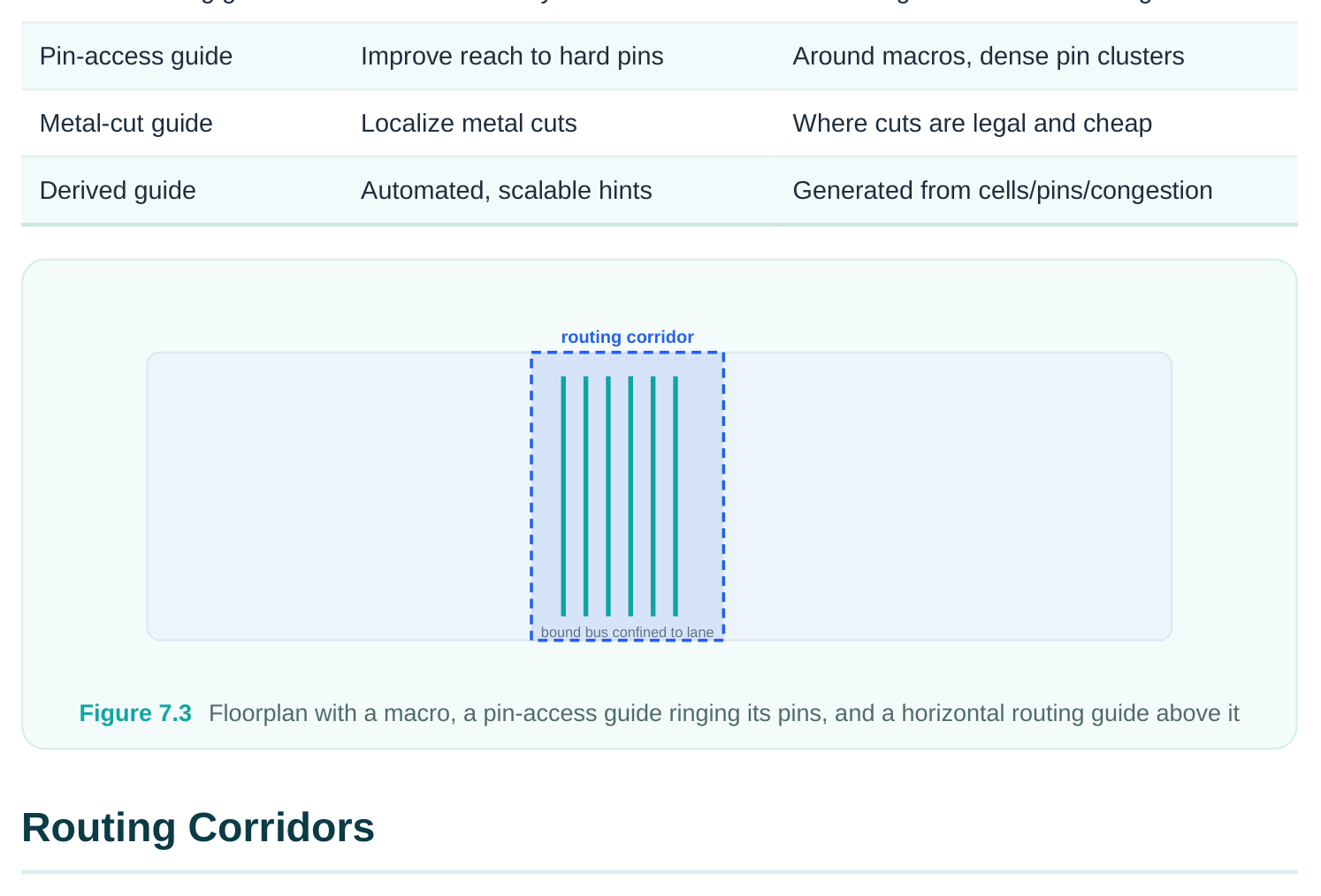
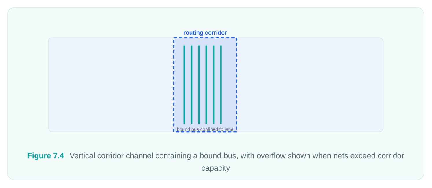
A routing corridor restricts a net (or set of nets) so that its routing is confined to a specific region of the layout. Where a guide nudges, a corridor constrains: nets bound to a corridor are not permitted to wander outside it. Corridors are the tool of choice when a bus must stay in a channel, when a feedthrough must follow a defined path, or when you want to reserve a clean lane for sensitive nets.
Restricting Nets to a Region
You build a corridor as a region, associate the target nets with it, and the router keeps those nets inside. This is how you implement "route this differential pair only through this shielded channel" or "keep these test nets in the spine."
# Create a vertical corridor and bind a sensitive bus to it
create_routing_corridor -name SENSE_BUS_CH \
-boundary {{200.0 50.0} {230.0 450.0}} \
-layers {M4 M5 M6}
add_to_routing_corridor -corridor SENSE_BUS_CH \
-nets [get_nets {sense_bus[*]}]
Adding Shapes and Changing Associated Nets
Corridors are editable objects. You can grow a corridor by adding shapes when the original region proves too tight, and you can change which nets are bound to it as the design evolves — releasing nets that no longer need protection or pulling in new critical nets. This iterative editing is routine during ECO-style closure.
# Widen the corridor and swap the net set during closure
add_shape_to_routing_corridor -corridor SENSE_BUS_CH \
-boundary {{230.0 50.0} {245.0 450.0}}
remove_from_routing_corridor -corridor SENSE_BUS_CH -nets [get_nets {sense_bus[7]}]
add_to_routing_corridor -corridor SENSE_BUS_CH -nets [get_nets {sense_bus[8]}]
The discipline to remember: a corridor that is too small will cause overflow and DRC, while a corridor with too many associated nets stops being a clean lane. Size the region and the net set together.
Mask / Color Constraints for Multi-Patterning
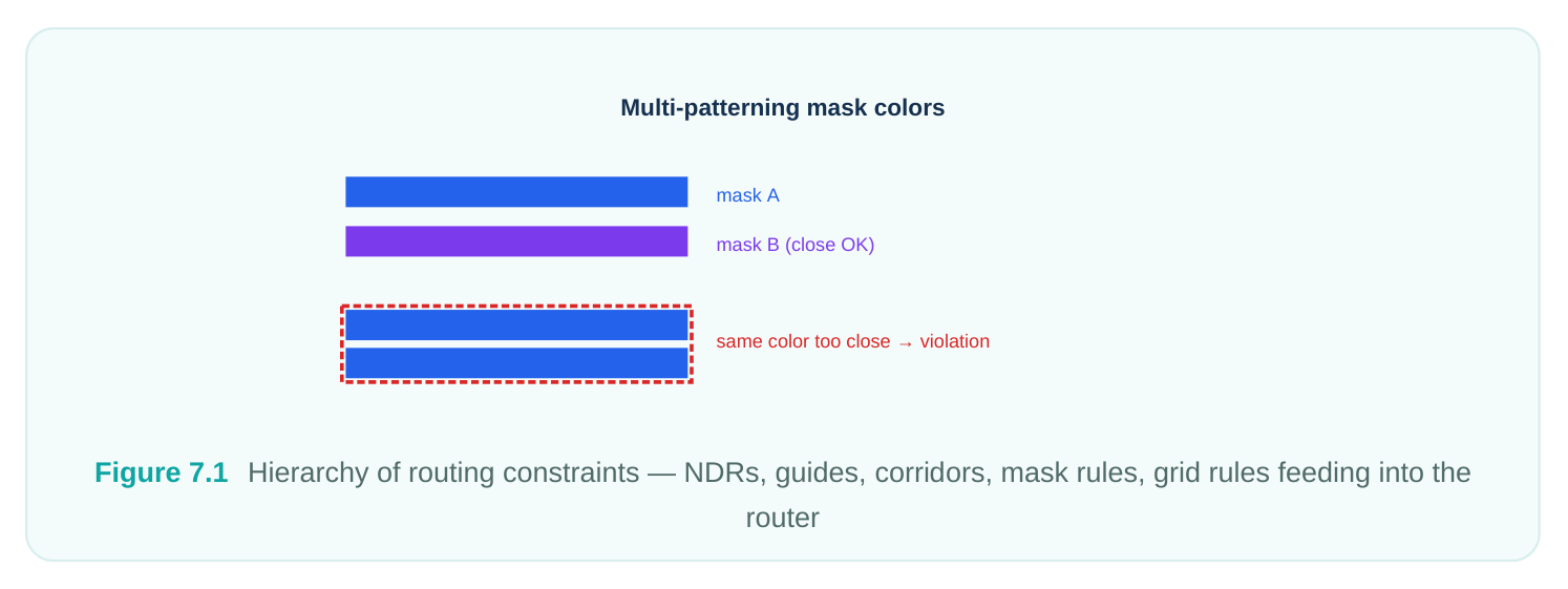
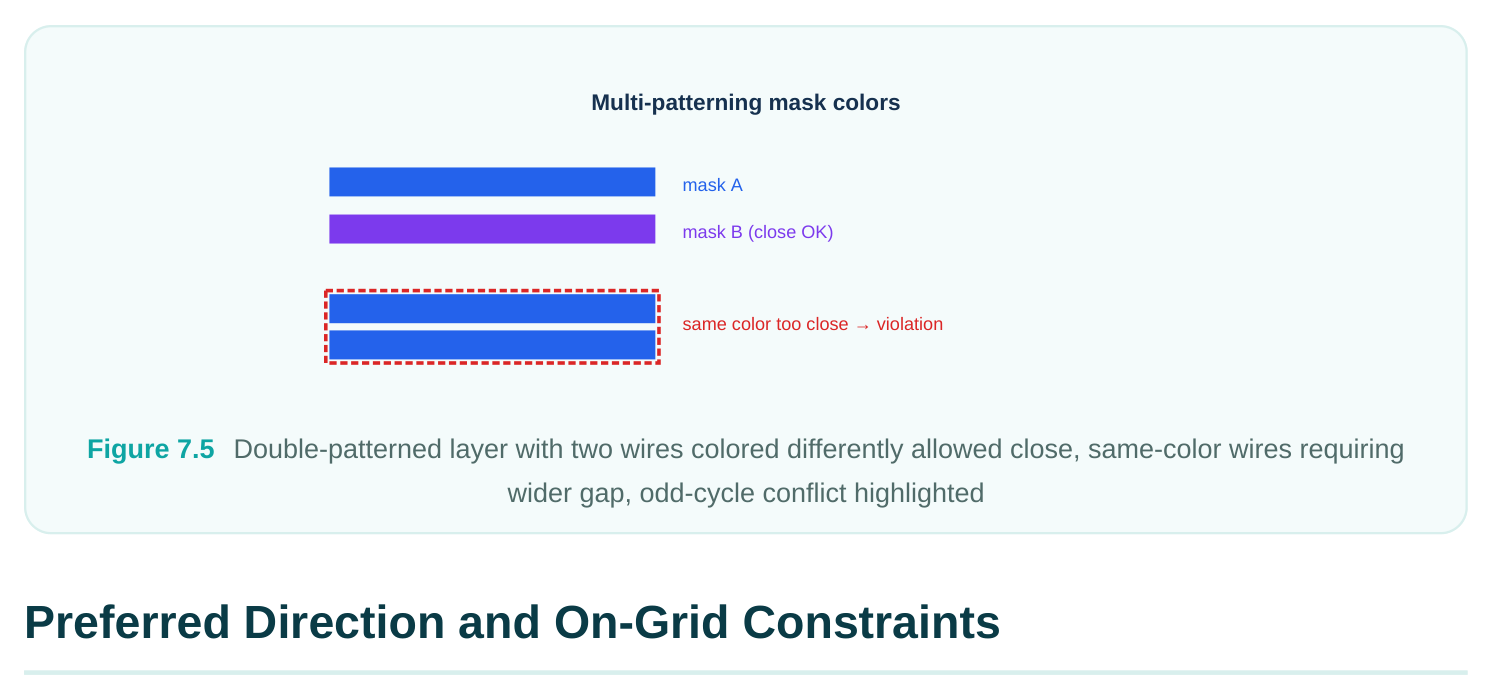
At advanced nodes a single mask cannot print the densest layers, so a layer is decomposed across two, three, or four masks — double, triple, or quadruple patterning. Each shape gets assigned a mask color, and shapes of the same color on the same layer must respect a larger same-mask spacing while opposite colors may sit closer. The router and the decomposition engine must keep these colorings legal, and you constrain them through mask/color rules.
Deriving Mask Colors
For shapes that are not pre-colored, the tool derives colors by solving the coloring problem on the layout graph: shapes too close to be on the same mask are forced to different colors. Where the graph cannot be two-colored (an odd cycle in double patterning), a coloring conflict arises and must be resolved by spacing or by inserting a stitch. You can ask the tool to derive and check colors explicitly.
# Derive mask colors on the multi-patterned layers and report conflicts
derive_mask_colors -layers {M1 M2 M3} -patterning double
check_mask_constraints -layers {M1 M2 M3} -report_conflicts true
Cut Mask Constraints
Cut (via) layers are also multi-patterned, and cut mask constraints govern how via cuts are colored relative to one another. Closely spaced cuts must split across masks; constraints can pin certain cuts to a fixed color (anchoring) or forbid two cuts from sharing a color. Honoring cut mask rules is essential for the multi-cut vias that NDRs introduce — a double via must place its two cuts so the coloring stays legal.
| Concept | What it governs | Failure mode if violated |
|---|---|---|
| Mask color assignment | Which mask prints each shape | Same-mask spacing violation |
| Same-mask spacing | Min gap for same-color shapes | Bridging / printability defect |
| Coloring conflict | Unsolvable color graph | Odd-cycle DRC, needs stitch/space |
| Cut mask constraint | Coloring of via cuts | Cut-to-cut same-mask violation |
The high-level point for an interview: multi-patterning turns spacing into a color-aware problem. Two wires that look legal by raw distance can still be illegal if they share a mask, and the router must reason about color, not just geometry.
The last family of constraints is the most fundamental and the most often taken for granted: the rules that align routing to the layer's intended direction and to the manufacturing grid.
Preferred Routing Direction
Each metal layer has a preferred direction — horizontal or vertical — typically alternating layer to layer to make orthogonal routing efficient. The router lays the bulk of a layer's wires along its preferred direction and uses short off-preferred jogs sparingly. Setting or correcting preferred direction is occasionally necessary, for instance after importing a tech file or when a custom layer needs an override.
# Confirm/override preferred routing direction per layer
set_preferred_routing_direction -layers M3 -direction horizontal
set_preferred_routing_direction -layers M4 -direction vertical
report_preferred_routing_direction
Excessive off-preferred routing is a red flag: it inflates congestion, wastes tracks, and usually signals a placement or pin-access problem upstream.
On-Grid Wire and Via Constraints
The routing grid (the set of legal track centerlines) and the via grid define where wires and vias may legally sit. An on-grid constraint forces the router to snap wire centerlines to routing tracks and via centers to grid intersections. On-grid routing is what keeps wires DRC-clean, keeps vias landable, and keeps the design compatible with downstream tools. Off-grid routing is sometimes permitted for special cases (pin access, certain analog structures), but for the digital bulk, on-grid is the rule.
| Constraint | Aligns to | Purpose |
|---|---|---|
| Preferred direction | Layer H/V orientation | Efficient orthogonal routing, low congestion |
| On-grid wire | Routing tracks | DRC-clean, track-aligned wiring |
| On-grid via | Via grid intersections | Landable, legal via placement |
Together these constraints make routing predictable: when wires sit on tracks and run in preferred directions, the router's congestion model and the design's DRC behavior both become tractable.
When Off-Grid and Off-Preferred Are Acceptable
No real route is perfectly on-grid and perfectly on-preferred-direction everywhere, and a good answer acknowledges the exceptions without abandoning the rule. Pin access is the classic case: a cell pin may not land exactly on a track, so the router makes a short off-grid jog to reach it and snaps back to the grid for the trunk of the wire. Off-preferred segments are similarly tolerated as brief jogs that swap a wire between tracks or step around an obstacle. The principle is locality and brevity — these deviations should be short, near their cause, and rare. The danger sign is systemic off-grid or offpreferred routing spread across a layer, which almost always traces back to a track definition that does not match the pin pitch, a misaligned via grid, or a placement that put incompatible pins on the same track. In those cases the fix is upstream, in the grid or placement, not in asking the router to try harder.
Interview Q&A
An NDR is a named rule attached to selected nets that overrides the technology default. It can change wire width (wider for lower resistance), spacing (extra gap for crosstalk/SI immunity), and via cuts (multiple/redundant cuts for reliability and EM). You create it with define_routing_rule and attach it with apply_routing_rule . Because it costs routing resources, you apply it selectively — clocks, critical nets, sensitive nets — rather than globally.
are defined at default geometry, so a 2x-wide wire often cannot physically land on a pin. The router tapers the NDR net back toward default width near the pin so it can make the connection, then widens out along the route. This is expected and legal behavior, not a violation — the wide, low-resistance body of the net is where the benefit lives, and the short taper near the pin has negligible electrical cost.
it biases the router's behavior in a region (preferred direction, allowed layers, utilization, pin access) but does not forbid nets from leaving. A corridor is a hard restriction: nets associated with the corridor are confined to its region. Use a guide to nudge routing around a macro or improve pin access; use a corridor to lock a sensitive bus or feedthrough into a defined channel. Guides shape behavior; corridors enforce containment.
Why? Because spacing is color-aware. If both wires are assigned the same mask color, they must respect the larger same-mask spacing, which can exceed the raw minimum. Opposite-color wires may sit closer. The flat-distance check passes, but the same-mask check fails. The fixes are to recolor one wire (if the coloring graph allows), add spacing, or insert a stitch — and if the layout contains an odd cycle, two-coloring is impossible and the geometry itself must change.
It tries to lay most wires along the preferred direction, so a wrong setting forces heavy off-preferred routing, which collides with the orthogonal layers above and below, spikes congestion, wastes tracks, and produces hard-to-route or DRC-laden results. The symptom is a layer choked with jogs and overflow; the cure is to set the correct H/V orientation with set_preferred_routing_direction and re-route. It also frequently exposes an upstream placement or pin-access issue.
Key Takeaways
- NDRs encode intent. Wider wires, extra spacing, and multi-cut vias are applied selectively to clocks, critical, and sensitive nets via
define_routing_rule+apply_routing_rule; expect tapering at pins. - Minimum geometry rules set hard floors. Width, spacing, and via-spacing minimums trade density against resistance, crosstalk margin, and yield — tighten or loosen per the design's need.
- Guides nudge, corridors confine. Use routing guides (general, pin-access, metal-cut, derived) for soft steering and corridors for hard net-to-region containment, and keep corridor size matched to its net set.
- Multi-patterning makes spacing color-aware. Derive mask colors, watch for odd-cycle coloring conflicts, and honor cut mask constraints — especially for the multi-cut vias NDRs create.
- Directional and on-grid constraints make routing predictable. Correct preferred direction and on-grid wire/via snapping keep wiring DRC-clean, landable, and congestion-tractable.
Comments
Leave a Reply