 ChipBuddy
← Home
ChipBuddy
← Home
Always-On Logic
When we shut down a region of a chip to save power, we make an implicit promise: the rest of the design will still be able to control that region, talk past it, and eventually bring it back to life. That promise can only be kept if a small, carefully chosen set of cells inside (or adjacent to) the shut-down region keep running even when everything around them goes dark. These cells form the always-on fabric of a low-power design. Get them right and your power gating works flawlessly; get them wrong and the chip either never wakes up, leaks current, or corrupts data on the way down. This chapter explains what always-on logic is, why ordinary cells cannot do the job, how the implementation tools build and place these cells, and the classic mistakes that turn an elegant power-gating scheme into a silent failure.
What "Always-On" Actually Means
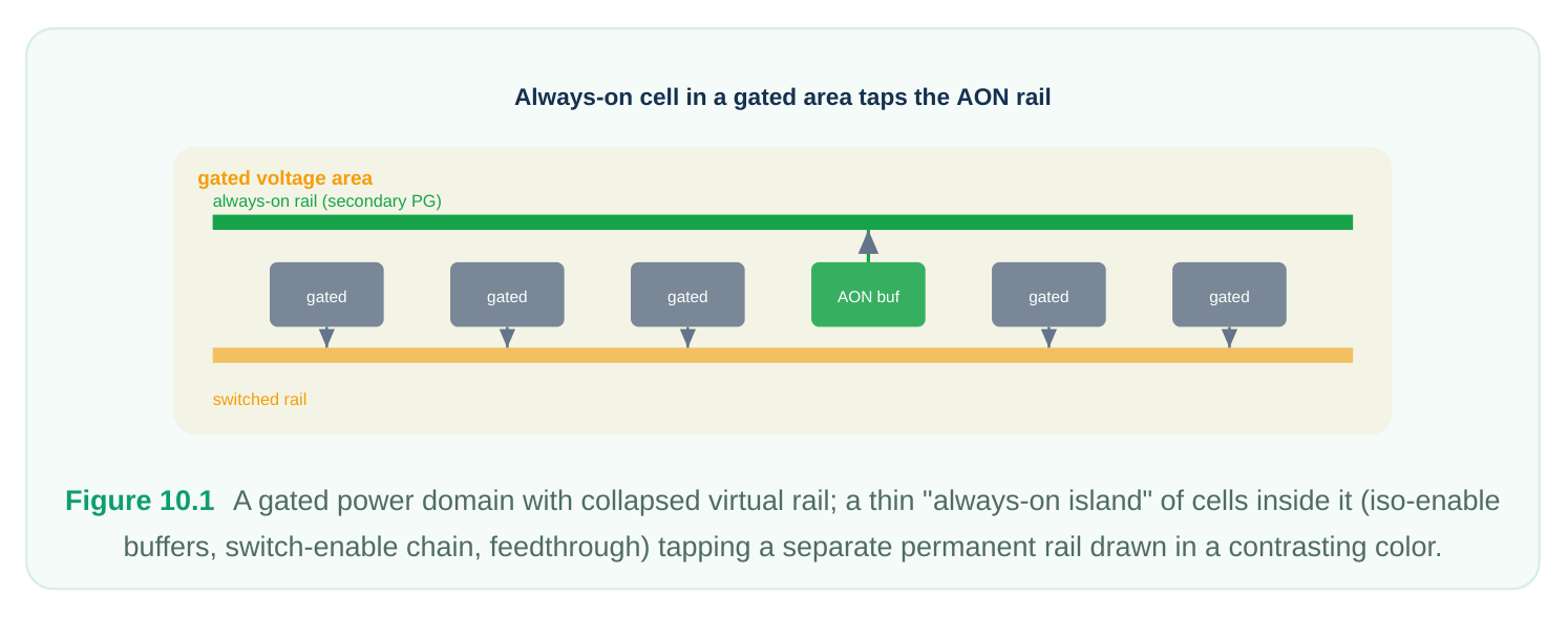
A power domain that can be switched off is fed through power switches from a permanent rail. When the switches open, the domain's local supply (often called the switchable or virtual rail) collapses to zero. Most logic in that domain is supposed to collapse with it — that is the whole point. But a handful of functions must survive the blackout because they are precisely the functions that manage the blackout:
- Isolation enable distribution. Isolation cells clamp the outputs of a sleeping domain so downstream live logic sees a defined value. The enable signal that drives those clamps must remain valid while the domain is off, so any buffering on that enable path must be always-on.
- Retention control. Retention registers need their save/restore (and sometimes a retention-clamp) control to stay live across the sleep interval. The logic that sequences and fans out these signals is always-on.
- Power-switch enable chains. The daisy-chained enable that turns the switch fabric on and off obviously cannot be powered by the rail it is switching. It runs from a permanent supply.
- Wake-up / sequencing logic. A small always-on controller (or a slice of one) watches for wake events and steps the domain back up in the right order.
- Feedthrough buffers. A signal that merely passes through the physical area of a gated domain to reach somewhere else must not die just because the local rail collapsed. Those pass-through buffers are made always-on. The common thread: these cells live in a region whose local rail can disappear, yet they themselves must not lose power.
Why Ordinary Buffers Won't Do
Inside a gated region, the default logic cell connects its power pin to the local switchable rail. That is correct for normal logic — when the domain sleeps, the cell sleeps and stops leaking. But it is fatal for control logic. If you let the synthesizer drop a standard buffer onto an isolation-enable net and that buffer sits physically inside the gated area, its supply collapses the instant the switches open. Its output floats, the isolation clamp it was supposed to drive becomes undefined, and the "protection" you carefully inserted does nothing. An always-on cell solves this by drawing power from a separate, permanent supply rather than the switchable rail. Physically, the cell exposes an extra power connection — a secondary power/ground (PG) pin — that is wired to the always-on rail, while the rest of the standard cells in that area connect to the switchable rail. The cell is built (in the standard-cell library) so that its logic transistors are fed from this secondary supply, sometimes with a dedicated backplane/well tie that keeps the device biased correctly even when the surrounding nominal rail is gone. The table below contrasts the two cell types as you would reason about them in an interview.
Ordinary (switchable)
Property Always-on cell
Power source Local switchable / virtual Permanent always-on rail
Survives domain No Yes
| Power connections | Single primary PG | Primary + secondary PG |
|---|---|---|
| Typical use | General domain logic | Iso enable, retention control, switch enable, |
feedthrough
Leakage when domain ~Zero (gated) Non-zero (always powered) — keep count small
Placement Anywhere in domain Inside the gated area, but power tied to AON rail while the rest of the domain saves power. So always-on logic is something you want to be correct and minimal at the same time.
How the Tool Identifies and Builds Always-On Nets
You rarely hand-instantiate every always-on buffer. Instead you declare intent in the power-intent file (the open IEEE 1801 / UPF standard), and the implementation tool figures out which nets must stay live and builds them from always-on cells. Conceptually the flow is:
- 1. Trace from the always-on consumers. The tool starts at signals that are known to need to remain
valid during shutdown — isolation enables, retention controls, switch enables. These are identified through the power-intent strategies you defined for the domain.
- 2. Walk the driver/fan-out tree. Any buffer or inverter inserted on those nets while the domain can be
off must itself be always-on. The tool marks these nets as requiring always-on synthesis.
- 3. Select always-on cells. During buffering and sizing, instead of choosing standard cells it picks
library cells that have a secondary PG pin associated with the always-on supply.
- 4. Voltage-aware buffering. If the always-on rail runs at a different voltage than the domain's nominal
rail, the tool must buffer with cells characterized at the always-on voltage. This is voltage-aware always-on buffering — getting the timing right means using the correct library corner for the supply that actually feeds the cell, not the one feeding its neighbors. A compact way to express the intent is to associate the always-on supply with the relevant supply set and let isolation/retention strategies reference it.
# Define the permanent always-on supply and a switchable domain supply
create_supply_port  VDD_AON
create_supply_net   VDD_AON
create_supply_net   VDD_SW
# The gated domain is powered by the switchable net;
# the always-on net is available for control logic
create_power_domain PD_CORE -elements {u_core}
create_power_domain PD_AON
# Power switch turns the switchable net on/off
create_power_switch sw_core \
-domain        PD_CORE \
-input_supply  VDD_AON \
-output_supply VDD_SW  \
-control_port  {sleep sw_en}
# Isolation strategy whose ENABLE must be always-on
set_isolation iso_core -domain PD_CORE \
-isolation_supply VDD_AON \
-clamp_value 0 -applies_to outputs
set_isolation_control iso_core -domain PD_CORE \
-isolation_signal iso_en \
-isolation_sense high
Because the isolation supply is the always-on net, the tool knows that the enable distribution and the clamp devices must be powered from VDD_AON , and it will buffer accordingly.
Physical Placement and Secondary PG Routing
Here is the subtle part that trips up newcomers: an always-on cell usually has to sit inside the physical area of the gated domain, but it must route its power to the always-on rail, not the switchable one that dominates that region. Why inside the gated area? Because the things it drives — isolation clamps on the domain boundary, retention pins on registers scattered through the domain, feedthrough endpoints — are physically there. Pulling every always-on buffer out to a separate region would create long, slow, congested routes. So the tool places always-on cells in the gated voltage area for locality, then connects their secondary PG pin to the always-on rail through dedicated secondary PG routing, while their primary PG (if present) follows the normal rail.
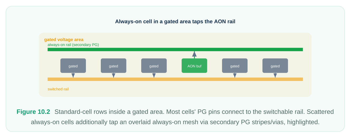
The floorplanning implication is real:
- The always-on rail must physically reach wherever always-on cells are placed. That usually means routing an always-on mesh or a set of secondary stripes across the gated region.
- The router must connect each always-on cell's secondary PG pin to that mesh, not to the nearest switchable stripe. A mistake here is invisible in logic but catastrophic in silicon.
- Some flows confine always-on cells to a sub-area or a ring so the always-on rail only needs to cover a smaller footprint, trading routing locality for a cleaner power plan. Item What it connects to Who routes it Ordinary cell primary PG Switchable rail Standard PG router Always-on cell primary PG Switchable rail (often) Standard PG router Always-on cell secondary PG Always-on rail Secondary PG routing step Isolation clamp supply Always-on rail Secondary PG routing Switch enable buffers Always-on rail Secondary PG routing
Custom Always-On Wrapper Cells and Backplane Ties
Not every always-on need is met by a single library cell. Two patterns show up repeatedly. Wrapper cells. When you have a block of logic that must remain alive — say a tiny wake controller — you can wrap it so the entire wrapped instance is treated as always-on, with the tool ensuring all internal buffering uses always-on cells and the wrapper's power pins map to the permanent supply. Conceptually a wrapper is a contract: "everything inside me is powered from the always-on rail; do not gate it." This is cleaner than tagging hundreds of individual nets. Backplane / well-tie support. In many low-power libraries the always-on cell needs more than just a secondary signal supply — it needs its transistor wells biased from a supply that does not collapse, otherwise the device characteristics drift when the nominal rail disappears. A library that supports always-on operation provides a backplane (well-bias) connection that ties to a permanent supply.
When you select always-on cells you are implicitly relying on that backplane tie being routed; the power plan must provide it. In an interview, the crisp statement is: an always-on cell may require both a permanent signal supply on its secondary PG pin and a permanent body-bias/backplane tie so the device stays correctly biased through shutdown.
Specifying Always-On Intent
Intent comes in two layers. The first is at the strategy level — isolation and retention strategies that name the always-on supply, as shown earlier. The second is at the port / pin attribute level, where you tell the tool that a specific boundary signal or a specific instance must be driven by, or associated with, the always-on supply.
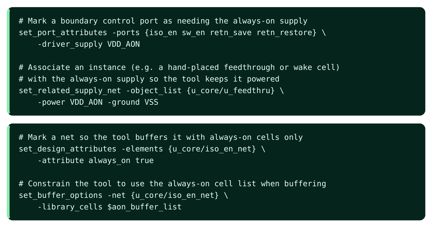
The exact attribute names vary by flow, but the principle is universal: you either (a) tell the tool which supply a port/instance is related to, or (b) tag the net as always-on so synthesis and buffering only ever pick cells with a secondary PG pin bound to the permanent rail. The power-intent strategies then make sure the secondary PG connections are honored downstream.
Pitfalls: Detection and Fix
Always-on bugs are dangerous precisely because the design simulates and even passes basic checks while powered up. The failures only surface when the domain is actually off. Pitfall 1 — Always-on buffer powered by the switched rail. The synthesizer (or a manual ECO) inserts a buffer on an isolation-enable net, but it picks an ordinary cell, or an always-on cell whose secondary PG accidentally got tied to the switchable rail. When the domain sleeps, the enable goes undefined and isolation fails. Detection: a power-intent / low-power static check (the standard rail and isolation checks every flow runs) flags any cell on an always-on net whose effective supply collapses with the domain. You are
looking for a report line that says, in effect, "net required to be always-on is driven by a cell on the switchable supply." Fix: re-buffer the net with always-on cells (constrain the cell list as above) and re-run secondary PG connection so the cell's secondary pin reaches the permanent rail. Pitfall 2 — Secondary PG not connected. The right cell is placed, but its secondary PG pin is left floating or never routed to the always-on mesh because the mesh did not extend to that location. Detection: PG connectivity / open-pin checks report an unconnected secondary power pin; a poweraware DRC flags the missing tie. Fix: extend the always-on mesh/stripes to cover the cell location and re-run secondary PG routing; if locality is poor, move the always-on cells into an area the mesh already covers.
# Sanity audit you can script before signoff:
# 1) every cell on an always-on net must be an always-on cell
report_cells -on_net [get_attribute -name always_on_nets [current_design]] \
-filter {is_always_on == false}
# 2) every always-on cell must have its secondary PG connected
report_pg_connectivity -pin_type secondary \
-filter {connected_net != VDD_AON || open == true}
Pitfall 3 — Wrong voltage buffering. Always-on cells are buffered using the nominal-domain library instead of the always-on-voltage library, so timing on the control path is silently optimistic. Detection: multi-voltage timing / library-corner checks show always-on cells analyzed at the wrong supply; the always-on rail's corner is missing from the analysis views. Fix: add the always-on voltage view and re-time, forcing voltage-aware buffering on those nets. A good habit: treat the always-on net list as a first-class object, run the audit script above at every checkpoint, and never let an ECO touch an always-on net without re-running the secondary PG step.
Interview Q&A
domain? A normal buffer connects to the domain's switchable rail. When the domain is shut down that rail collapses, so the buffer loses power and its output floats. The isolation enable then becomes undefined exactly when it is needed, defeating the isolation. An always-on buffer is required because it taps a permanent supply through its secondary PG pin and keeps driving a valid enable through shutdown.
ground connection on the cell, separate from the primary PG. For an always-on cell the secondary PG is tied to the permanent (always-on) rail, which is what keeps the cell's logic alive while its physical neighbors lose the switchable rail. It matters because the cell can be placed inside the gated area for
routing locality yet still draw power from the always-on mesh — provided that secondary pin is actually routed to it. A floating secondary PG is a classic silent failure.
what does the floorplan need to provide? Its primary connections may follow the switchable rail, but its secondary PG (and, where required, its backplane/well-bias tie) connects to the permanent alwayson supply. The floorplan must therefore extend an always-on mesh or secondary stripes to wherever always-on cells are placed, and the secondary PG routing step must connect each cell's secondary pin to that mesh rather than to the nearest switchable stripe.
switched-rail cell, and how do you fix it? Run the flow's low-power rail/isolation static checks; they flag any cell on a required-always-on net whose effective supply collapses with the domain, or any always-on cell with an unconnected/wrongly-tied secondary PG. The fix is to re-buffer the net constrained to the always-on cell list, then re-run secondary PG connection so the cells reach the permanent rail — and re-time with the correct always-on voltage view to be sure the buffering was voltage-aware.
Key Takeaways
- Always-on cells keep critical control alive during shutdown — isolation enables, retention controls, switch-enable chains, wake logic, and feedthroughs — by drawing power from a permanent rail via a secondary PG pin.
- Ordinary cells fail inside gated regions because their supply collapses with the domain; intent in the power-intent (IEEE 1801) file tells the tool which nets must be always-on so it buffers them with the right cells.
- Placement is local but power is remote: always-on cells live inside the gated area, yet their secondary PG (and any backplane tie) must route to the always-on mesh, which the floorplan has to provide.
- Voltage-aware buffering is essential when the always-on rail differs from the nominal rail — analyze and buffer at the supply that actually feeds the cell.
- The two killer bugs are a switched-rail cell on an always-on net and an unconnected secondary PG. Both pass powered-up checks and only fail when the domain is off, so run rail/ isolation static checks and a secondary-PG connectivity audit at every checkpoint and after every ECO.
- Keep the always-on set minimal: every always-on cell leaks while the rest of the domain saves power, so correctness and economy must be balanced.
Comments
Leave a Reply