 ChipBuddy
← Home
ChipBuddy
← Home
Retention Strategies
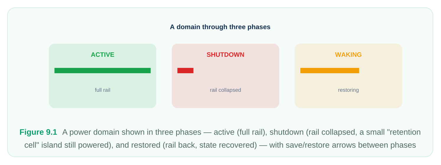
Power gating is the most aggressive leakage-reduction technique available to a low-power designer: collapse the supply to an idle block and its leakage drops to nearly nothing. But that aggression comes with a cost that this chapter is entirely about. The moment you remove the rail, every sequential element in the domain forgets what it knew. Flip-flops, latches, and small memories all return to an undefined state. When the block wakes up, it is not "resuming" — it is starting from scratch. For some blocks that is perfectly acceptable. A purely combinational accelerator that recomputes its result every time it runs does not care that its internal pipeline registers were wiped. But for a great many blocks, throwing away state is unaffordable. A processor mid-context, a protocol engine tracking a connection, a control FSM holding configuration — these need their state back, and they need it fast. Re-deriving that state in software (reloading configuration registers, replaying a boot sequence, reestablishing a link) can take thousands of cycles and burn far more energy than the gating saved. The retention problem is the gap between "the rail is off" and "the block is instantly useful again." This chapter develops the engineering answer to that gap: state retention — preserving selected sequential state on an always-on rail across the off period, then restoring it on wake.
Why losing state is expensive
Before reaching for retention, it is worth being precise about the trade-off, because retention is not free. The decision is fundamentally about wake-up latency and wake-up energy versus standby leakage and area. If you retain nothing, your standby power approaches the floor — only the always-on infrastructure leaks — but your wake-up is slow because state must be rebuilt. If you retain everything, wake-up is nearly instantaneous but you pay continuous leakage in the retention storage and consume extra area for it. Real designs live between these extremes, retaining only what is needed for a fast, correct resume.
| Wake-up | Area | |||
|---|---|---|---|---|
| Approach | Standby leakage | Typical use | ||
| latency | cost | |||
| No retention (cold | Lowest | Highest (rebuild | None | Stateless accelerators, blocks |
| restart) | state) | idle for long periods | ||
| Selective retention | Low | Low–moderate | Moderate | Most real subsystems — retain |
only critical state
| Full retention | Higher (retention | Lowest | Highest | Latency-critical blocks, short idle |
|---|---|---|---|---|
| leakage) | windows |
The phrase "retain only what is needed" is the heart of good retention design and we will return to it.
The retention flop concept
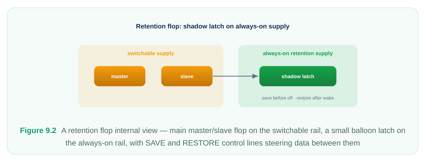
The workhorse of state retention is the retention flop (often called a retention register or stateretention cell). Conceptually it is an ordinary flip-flop augmented with a small auxiliary storage element — commonly drawn as a shadow latch or balloon latch — that sits on a separate, always-on supply. In normal operation the main flop runs on the switchable domain supply and behaves exactly like a regular register; the shadow element is idle. When the system decides to power down the domain, it issues a save event: the current value of the main flop is copied into the shadow latch. The shadow
latch keeps that value alive on its always-on rail while the main domain rail collapses and the main flop's value evaporates. On wake, after the main rail is restored and stable, a restore event copies the value from the shadow latch back into the main flop. The block resumes as though it never slept. Two supplies are therefore in play inside one cell:
- The primary (switchable) supply powers the main flop and the bulk of the domain logic. It is collapsed during shutdown.
- The retention (always-on) supply powers only the tiny shadow storage and its control. It must remain valid for the entire off period. The shadow latch is deliberately small and slow — it only has to hold a value, not switch at speed — so its leakage is a small fraction of keeping the whole domain alive. That asymmetry is exactly what makes retention worthwhile: you pay always-on leakage for a few bits per register instead of for the entire domain.
Control signals and their meaning
Retention cells are driven by dedicated control. Two common conventions exist:
- 1. Separate save and restore signals — one pin pulses (or asserts) to capture state into the shadow
latch before shutdown; a different pin pulses to push state back into the main flop after wake.
- 2. A single retention-control signal — one signal whose assertion means "enter retention / save
now" and whose de-assertion (after power is back) means "exit retention / restore now." The cell internally derives the two edges. Whichever convention a library uses, the control must itself live on the always-on domain — if the save/restore signal disappears when the main rail collapses, the cell will never have been told to save, or will glitch on the way down. This is one of the most common and most painful retention bugs, and we will treat it explicitly later.
Granularity: full versus selective retention
How much state should you retain? This is a design choice with real consequences.
Full retention maps every flop in the domain to a retention cell. Wake-up is fastest because nothing has to be recomputed. The price is paid twice: every retention cell is larger and leakier than a plain flop, and the always-on retention rail must supply all of them, so standby leakage rises. Selective retention retains only the registers that are genuinely needed to resume correctly — configuration, mode, connection state, a program counter, key control-FSM state — and lets everything else (datapath pipeline registers, scratch, transient state) take a cold restart. The rest of the state is either recomputed quickly on wake or simply does not matter because the block reinitializes those paths anyway. Selective retention is almost always the better engineering answer, but it demands that you actually understand the block: which bits are "live state" and which are "derivable." Getting this wrong in the conservative direction (retaining too much) wastes leakage and area; getting it wrong in the aggressive direction (retaining too little) produces a block that wakes up subtly broken. Identifying the minimal correct retention set is a genuine architectural task, not a mechanical one.
Cell variants: zero-pin and live-slave
Library vendors offer several physical realizations of the retention idea. Two conceptual families are worth knowing for interviews. A zero-pin (or self-controlled) retention cell hides the save/restore control inside the cell. Instead of routing explicit save/restore signals, the cell senses the state of its own supplies — for example, detecting that the primary rail is collapsing — and triggers the save/restore internally. This saves routing and simplifies the power-intent specification, at the cost of less explicit control and tighter dependence on supply-sequencing behavior. A live-slave (or balloon-on-slave) cell reuses the flop's slave latch as the retention element by holding it on the always-on rail while the master and surrounding logic collapse. Because it repurposes existing storage rather than adding a dedicated balloon, it can be more area-efficient, but the alwayson slave path constrains how the cell is built and how it behaves during the off period. The takeaway is not the implementation detail but the principle: the standard cell library gives you a menu of area / leakage / control-complexity trade-offs, and the strategy you write in your power intent picks from that menu.
Specifying a retention strategy in power intent
In the open power-intent standard (IEEE 1801), retention is declared as a property of a power domain. You name the domain, identify which registers retain, point at the retention (always-on) supply, and bind the save and restore control. The exact command names vary, but the shape is consistent across the generic forms shown below. A minimal retention specification typically does three things: declares the strategy and its supply, names the control signals, and (optionally) scopes which registers it applies to.
# Declare a retention strategy on a power domain.
# Bind it to the always-on retention supply set.
set_retention ret_strategy_cpu \
-domain        PD_CPU \
-retention_power_net  VDD_AON \
-retention_ground_net VSS
# Bind the save and restore control signals.
# These signals must originate on an always-on domain.
set_retention_control ret_strategy_cpu \
-domain  PD_CPU \
-save_signal    { pmu_save    high } \
-restore_signal { pmu_restore high }
To implement selective retention, you restrict the strategy to a chosen set of registers rather than applying it to the whole domain. The intent below retains only configuration and control state and lets the datapath cold-start.
# Selective retention: apply only to named registers / groups.
set_retention ret_strategy_cfg \
-domain        PD_CPU \
-retention_power_net  VDD_AON \
-retention_ground_net VSS \
-elements { u_cfg_regs  u_mode_fsm  u_pc_reg }
set_retention_control ret_strategy_cfg \
-domain  PD_CPU \
-save_signal    { pmu_save    high } \
-restore_signal { pmu_restore high }
A single-control-signal style collapses save and restore into one retention signal whose level distinguishes the two phases:
# Single retention-control convention:
#   assert  -> save and hold (entering retention)
#   release -> restore (after primary rail is valid again)
set_retention ret_strategy_io \
-domain        PD_IO \
-retention_power_net  VDD_AON \
-retention_ground_net VSS
set_retention_control ret_strategy_io \
-domain  PD_IO \
-retention_signal { pmu_retain high }
The verification and implementation flow will turn these declarations into actual retention cells, route the always-on supply to them, and check that the control signals are themselves always-on and correctly sequenced.
The save/restore sequence relative to isolation and power-down
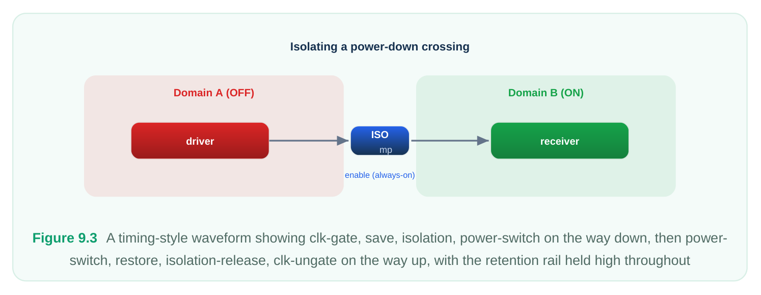
Retention does not act alone. It is one step in an ordered choreography that also involves clock gating, isolation (clamping the domain's outputs so downstream always-on logic sees safe values), and the power switch that actually collapses the rail. Getting this ordering wrong is the single richest source of retention bugs, so memorize the sequence in both directions. The general principle on the way down is: quiesce, then save, then isolate, then cut power. On the way up it reverses: restore power, then restore state, then de-isolate, then resume. The save must happen while the main flop still has valid data and a valid supply; the restore must happen after the main rail is back and stable.
| Step | Power-down (sleep) sequence | Power-up (wake) sequence |
|---|---|---|
| 1 | Stop activity: gate the clock to the domain so values are stable | Re-apply the primary (switchable) rail; let it settle |
| 2 | Assert save — capture live state into the shadow | Assert reset paths if required by the cell type |
latches
3 Assert isolation — clamp domain outputs to safe De-assert save / hold (retention still engaged)
| 4 | Open the power switch — collapse the primary | Assert restore — push shadow state back into |
|---|---|---|
| rail | main flops | |
| 5 | Domain is now off; only retention rail and always- on logic live | De-assert isolation — release clamped outputs |
| 6 | — | Un-gate the clock; the domain resumes normal |
operation Two ordering rules deserve emphasis because they are the ones interviewers probe:
- Save before isolate, save before power-down. If you isolate or cut power before the save completes, you capture clamp values or garbage instead of real state.
- Restore after the rail is valid, before de-isolation and clocking. Restoring into a flop whose primary supply has not settled produces unreliable data; releasing isolation or clocking before restore completes lets undefined state escape into the rest of the chip.
Common errors: detection and fix
Retention bugs are notorious because they often pass functional simulation that ignores power and only surface in power-aware verification or, worse, in silicon. Here are the recurring ones. Retention supply not actually always-on. The shadow latch is mapped to a net that itself gets collapsed (or is fed from the switchable domain through a missing always-on path). State is "retained" into a latch that dies along with everything else. Detection: power-aware structural checks flag retention cells whose retention rail is not driven by an always-on supply, or show the retention net toggling during shutdown in a power-aware simulation. Fix: route the retention power/ground from a genuine always-on supply set and re-confirm the always-on attribute in the power intent. Save/restore ordering wrong. Save asserted after isolation, restore asserted before the rail settles, or restore released before it completes. Detection: power-aware simulation shows corrupted state on wake; assertion-based or sequence checks on the control protocol fire; the post-wake values do not match pre-sleep values. Fix: correct the controller (PMU) sequencing so save precedes isolate/powerdown and restore follows a stable rail and precedes de-isolation and clocking. Control signals on the wrong domain. The save/restore (or single retention) signal is generated inside the switchable domain, so it vanishes or glitches as the rail collapses, and the cell is never properly told to save or to hold. Detection: checks reporting retention control sourced from a nonalways-on domain; glitches on the control net during the power-down window. Fix: generate retention control from an always-on controller and verify its supply. Retaining too much (or too little). Mapping every flop to a retention cell inflates leakage and area for no benefit; retaining too few registers leaves the block functionally broken after wake. Detection:
leakage/area reports show retention cells dominating standby power (too much); post-wake functional mismatches on specific registers reveal missing retention (too little). Fix: revisit the architectural retention set — retain exactly the live state needed for a correct, fast resume, and let derivable state cold-start. Missing or mis-ordered isolation around retention. Even with correct retention, if outputs are not clamped while the rail is down, downstream logic samples floating or corrupted values. Detection:
isolation-coverage checks; X-propagation in power-aware simulation. Fix: ensure every crossing from the gated domain to an always-on consumer has isolation, sequenced as in the table above.
Interview Q&A
retention cells? You can — that technique exists (often called state-retention via voltage scaling or a "data-retention voltage" mode), but it keeps the entire domain leaking, just at a reduced level. Retention cells let you collapse the bulk of the domain completely and pay always-on leakage only for a few bits per retained register. For a domain dominated by combinational logic and datapath, dedicated retention cells reach a far lower standby floor for the same wake-up speed. The voltagefloor approach makes sense when nearly all the state must survive and the control overhead of cells is not worth it.
and isolate swap? Going down: gate the clock, assert save (capture live state into the shadow latch), assert isolation (clamp outputs), then open the power switch. If save and isolate swap, isolation clamps the domain's outputs first — and if any retained register's input or capture path is affected by those clamped values, or if isolation is taken as a signal to begin collapsing, the save captures clamp values rather than real state. You wake up holding the isolation constant instead of your true pre-sleep data.
recomputed cheaply — configuration, mode, connection/session state, program counter, key FSM state) and "derivable" (pipeline, scratch, transients that the block reinitializes anyway). Retain the live set; cold-start the rest. The goal is the minimal set that yields a correct, fast resume. Over-retaining wastes leakage and area; under-retaining produces a block that wakes up subtly wrong. This requires real understanding of the block's architecture, which is why it is an architectural decision rather than a tool default.
simulation passes. Where do you look? Functional simulation that ignores power will not exercise the rail collapse, so retention bugs hide there — that mismatch is itself the clue. Run power-aware simulation and check, in order: is the retention rail genuinely always-on (or does it toggle during shutdown)? Are the save/restore control signals sourced from an always-on domain, or do they glitch as the rail drops? Is the sequencing correct (save before isolate/power-down; restore after a stable rail and before de-isolation/clocking)? And is the right set of registers actually mapped to retention cells? Power-aware structural and sequence checks will usually pinpoint which of these failed.
Key Takeaways
- Power gating destroys sequential state; retention preserves selected state on an always-on rail so the domain can wake quickly and correctly.
- A retention flop is a normal flop plus a small shadow/balloon latch on an always-on supply: save before shutdown, restore after wake.
- Two supplies coexist in the cell — the switchable primary supply for the main flop, the always-on retention supply for the shadow storage and its control.
- Retention control (save/restore or a single retention signal) must itself be always-on, or the cell is never correctly told to save or hold.
- Granularity is a deliberate trade: full retention gives the fastest wake at the highest leakage/area; selective retention — retaining only live state — is usually the right engineering answer.
- Sequencing is everything: down is quiesce → save → isolate → power-down; up is rail-valid → restore → de-isolate → clock. Save before isolation; restore after a stable rail.
- The classic failures — retention rail not actually always-on, wrong save/restore order, control on the wrong domain, and retaining too much or too little — are caught by power-aware (not plain functional) verification, so always validate retention in a power-aware flow.
Comments
Leave a Reply