 ChipBuddy
← Home
ChipBuddy
← Home
Multivoltage Sign-Off & Quick Reference
This is where the book closes the loop. Across the previous chapters you learned each multivoltage construct in isolation — power domains, supply sets, switches, isolation, level shifters, retention, wellbias, and the verification machinery that polices them. Sign-off is the moment you prove that every one of those constructs works together, in every operating mode, under every corner, with nothing left implicit. A multivoltage chip does not fail because an engineer forgot what an isolation cell does. It fails because one crossing in one rarely-exercised mode had no isolation, and nobody noticed until silicon came back dark. The discipline of multivoltage sign-off is therefore exhaustiveness, not cleverness. You are building a case — a body of evidence — that the power intent is correct, that it was implemented faithfully, and that the implementation still meets timing and power once the real cells and real parasitics are in place. This chapter gives you the structured checklist, the mode-coverage discipline, the pitfall catalog, and a consolidated command reference you can carry into any flow. Think of sign-off as three nested questions, each of which must be answered "yes" before the next is even meaningful. Is the intent correct? — does the power-intent specification describe a chip that can actually function in every mode you promised the customer? Was the intent implemented? — did the physical netlist, with its inserted isolation, level shifters, retention cells, switches, and routing, faithfully realize that specification with nothing dropped or substituted? Does the implementation still close? —
once you layer in real cell delays, real parasitics, and the voltage scaling of every operating point, do timing and power both meet budget? A failure at any level invalidates everything above it. There is no point celebrating a clean timing run on a netlist whose isolation strategy was incomplete, and no point trusting an equivalence check that ran against a stale intent file. Sign-off is a chain of trust, and the chain is exactly as strong as its weakest verified link.
What Must Be True Before You Sign Off
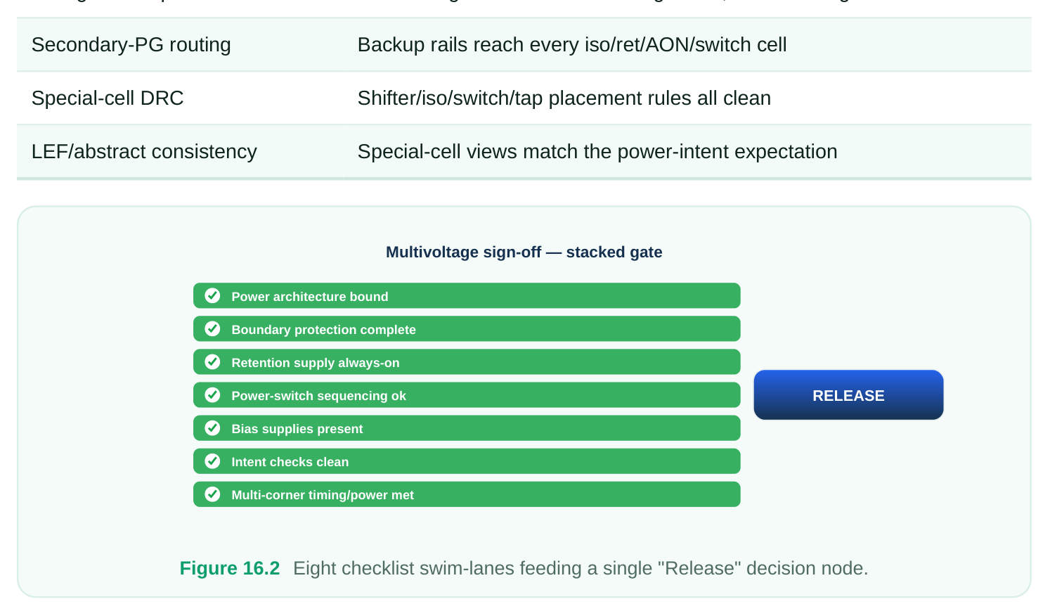
Sign-off is a conjunction: every clause must hold. There is no partial credit. Before you release a multivoltage design, all of the following must be simultaneously true.
- The power architecture is fully bound. Every power domain has a defined primary supply, every supply net resolves to a real source, and there are no floating or unconnected supplies anywhere in the netlist.
- Every domain crossing is protected. Isolation exists on every signal that leaves a switchable domain toward a domain that can be on while the source is off. Level shifters exist on every signal that crosses a voltage boundary, in every mode where that boundary exists.
- State survives power-down where the spec requires it. Retention registers have an always-on retention supply, and their save/restore sequencing is ordered correctly relative to the switch and the clock.
- Always-on logic is genuinely always-on. Isolation control, retention control, level-shifter enables, and switch enables are powered by a supply that is never gated, with the secondary power/ground pins correctly connected.
- Switches sequence and behave. Power-switch enable chains are ordered, inrush is bounded, and the IR drop across the switch fabric is within budget for the worst on-current.
- Bias is supplied. If the design uses well-bias for leakage control or performance tuning, the bias supplies are present, routed, and within range in every mode.
- Verification is clean. Static power-intent checks pass with zero unwaived violations, power-aware logical equivalence holds against the golden RTL with power intent applied, and multi-corner timing and power sign-off both close.
- The physical implementation is legal. Voltage areas are placed and abutted correctly, secondary-PG routing reaches every special cell, and special-cell DRC (switch arrays, isolation/ level-shifter placement rules, well-tie spacing) is clean.
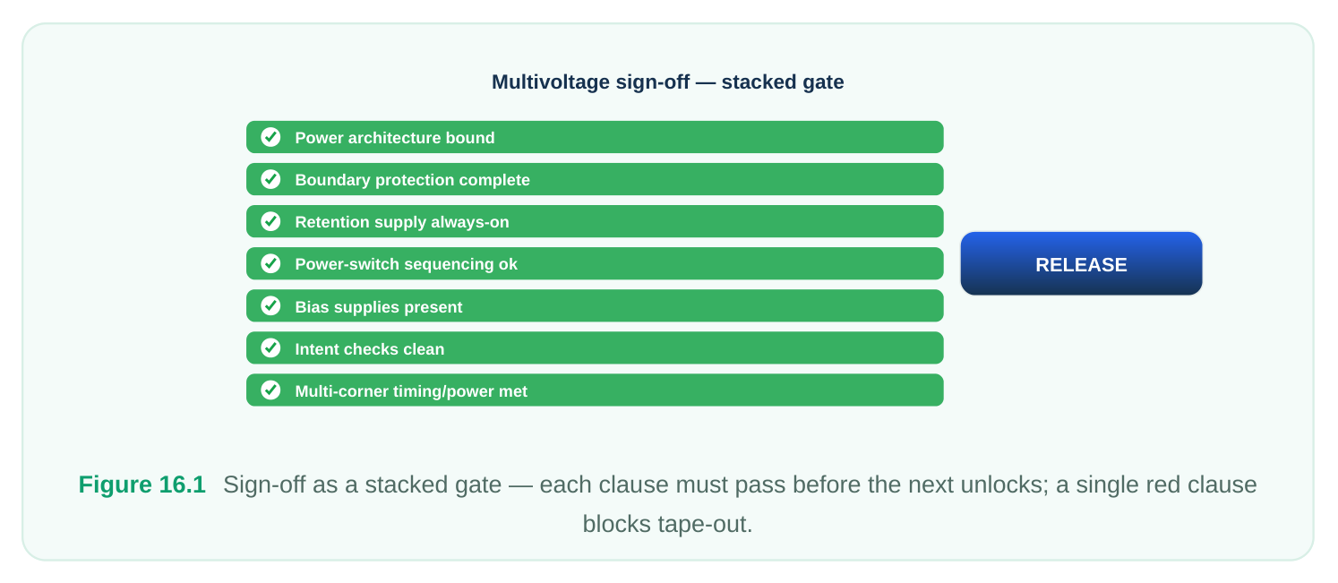
A useful mental discipline is to assign each of these clauses an owner and an artifact. The owner is the engineer who personally signs that the clause is true; the artifact is the report, log, or waiver review that proves it. "The architecture is bound" is not a feeling — it is a domain report with zero floating supplies attached to it. "Verification is clean" is not optimism — it is an intent-check log with zero unwaived violations and a reviewed waiver list. When you frame sign-off this way, the release meeting becomes a roll-call: each owner states their clause and points to their artifact. Anything without an artifact is, by definition, not signed off.
The Structured Sign-Off Checklist
Use this grouped checklist as your literal close-out worksheet. Each row is a question you must be able to answer "yes, verified" to — not "probably."
POWER ARCHITECTURE
| Check | What "pass" looks like |
|---|---|
| All domains created and scoped | Every instance belongs to exactly one power domain; no orphan logic |
| Primary supply bound per domain | Each domain has a resolved primary power/ground pair |
| No floating supplies | Every supply net traces to a port, a switch output, or an external source |
| Supply sets consistent | Function-to-net mapping is complete; no half-defined supply set |
| Domain hierarchy sane | Parent/child domain nesting matches the physical voltage areas |
BOUNDARY PROTECTION
| Check | What "pass" looks like |
|---|---|
| Isolation on every power-down | Every signal from a switchable domain to an on domain is clamped |
crossing
Isolation clamp value correct Clamp (0/1/latch) matches the receiver's reset/functional
Isolation enable is always-on Control comes from an ungated supply, asserted before power-
| Level shifter on every voltage crossing | Each signal crossing V_high↔V_low has a shifter, in every mode |
|---|---|
| Shifter direction and type correct | Up/down/bidirectional and enable-style matches the crossing |
RETENTION
| Check | What "pass" looks like |
|---|---|
| Retention supply always-on | Retention rail is never gated for the duration of power-down |
| Save/restore ordering | Save before switch-off; restore after switch-on, before clocks resume |
| Retention strategy complete | Every register required to survive is on a retention strategy |
| Control signals protected | Save/restore controls are isolated and always-on |
ALWAYS-ON (AON)
| Check | What "pass" looks like |
|---|---|
| Secondary PG connected | AON cells' backup power/ground pins reach the always-on rail |
| AON cells truly ungated | No switch sits between AON logic and its supply |
| Control net AON-routed | Iso/ret/shifter/switch enables stay live during power-down |
POWER SWITCHES
| Check | What "pass" looks like |
|---|---|
| Enable chain ordered | Daisy-chained acknowledge confirms full domain ramp |
| IR across switch in budget | On-state drop keeps gated supply within timing-valid range |
| Inrush bounded | Staggered turn-on limits peak ramp current on the always-on rail |
| Switch array DRC clean | Switch placement, strap, and ring rules satisfied |
BIAS
| Check | What "pass" looks like |
|---|---|
| Well-bias supplies present | N-well/P-well bias rails defined where used |
| Bias within range per mode | Reverse/forward bias values legal for each operating mode |
| Bias routing complete | Bias rails reach all tap cells in the biased region |
VERIFICATION
| Check | What "pass" looks like |
|---|---|
| Power-intent static checks clean | Zero unwaived violations from the intent checker |
| Power-aware equivalence | RTL-with-intent equals netlist-with-intent, isolation/iso-logic matched |
| Multi-corner timing | Setup/hold close at all relevant V/T corners including scaled rails |
| Multi-corner power | Leakage and dynamic power within budget across modes and corners |
PHYSICAL
| Check | What "pass" looks like |
|---|---|
| Voltage areas placed | Domain logic confined to its voltage area; abutment legal |
Power-State / Mode Coverage
The single most important table in any multivoltage sign-off is the mode-coverage matrix. It declares, per mode, what state each domain is in — and your sign-off must prove that every listed mode and every transition between modes was actually verified. A boundary that is safe in three modes can be lethal in the fourth. Consider a representative four-domain SoC: an always-on controller (AON), a CPU cluster (CPU), a graphics/DSP block (GFX), and an I/O domain (IO).
| Mode | AON | CPU | GFX | IO | Verified |
|---|---|---|---|---|---|
| Active-Full | On (nominal) | On (nominal) | On (nominal) | On | Timing ✔ / Power ✔ |
| Active-Scaled | On (nominal) | On (scaled-low) | On (nominal) | On | Timing ✔ / Power ✔ |
| GFX-Off | On (nominal) | On (nominal) | Off | On | Iso ✔ / Power ✔ |
| Compute-Only | On (nominal) | On (nominal) | Off | Off | Iso ✔ / Power ✔ |
| Standby-Retain | On (nominal) | Off (retained) | Off | Off | Ret ✔ / Iso ✔ |
| Deep-Sleep | On (nominal) | Off | Off | Off | Iso ✔ / Leakage ✔ |
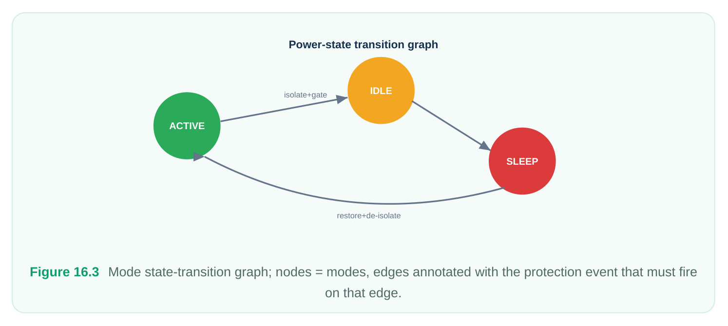
Then prove the transitions, because the hazardous moment is the edge, not the state:
| Transition | Hazard checked | Pass criterion |
|---|---|---|
| Active → GFX-Off | GFX outputs glitch during ramp- | Isolation asserts before switch-off |
down
| GFX-Off → Active | Inrush on AON rail | Staggered enable, IR within budget |
|---|---|---|
| Active → Standby-Retain | CPU state loss | Save asserts before CPU switch-off |
| Standby → Active | Corrupt restore | Restore after ramp, before clock |
release
Active-Full → Active- Cross-rail timing at low V Level shifters valid at scaled voltage A mode is not "covered" because it appears in the table. It is covered when (a) static intent checks confirm protection exists for that state, (b) timing closed at that state's corner, and (c) the transitions into and out of it were sequence-verified. Track the "Verified" column to closure and refuse to sign off on any blank cell. Two coverage traps deserve special mention because they survive casual review. The first is the implicit mode — a state the silicon can physically enter that nobody wrote into the matrix. If your power-management controller has a path that turns CPU and GFX off while IO is still ramping, that intermediate state exists whether or not it has a row. Derive the matrix from the controller's actual state
machine, not from the marketing list of advertised modes. The second trap is the asymmetric transition. Entering a mode and leaving it are different events with different hazards: entry to a retention state stresses save ordering, while exit stresses restore-then-release ordering and inrush. A matrix that verifies states but only spot-checks transitions will pass a chip that glitches on wake-up. Treat every directed edge of the transition graph as its own verification target, and only color a node green when all of its incident edges are also green.
The Most Common Multivoltage Pitfalls
These are the failures that recur across teams and technologies. Most are not subtle in hindsight — they are gaps that survived because no single check was responsible for catching them.
| Pitfall | Why it bites | How to avoid |
|---|---|---|
| Missing isolation in a | Crossing safe in main modes, | Drive isolation from the full mode matrix, |
| rare mode | exposed in an edge mode | not the common path |
| Isolation control gated by | Enable comes from a switchable | Force all control nets onto a verified |
| accident | supply, floats at power-down | always-on supply |
| Level shifter omitted on a | Crossing only becomes a voltage | Re-run shifter checks per mode, |
| scaled rail | boundary in scaled mode | including DVFS scaled states |
| Retention supply | Retained state lost when the | Assert retention rail is ungated in every |
| accidentally switched | "always-on" rail wasn't | mode in the matrix |
| Save/restore mis- | State corrupted on restore or save ordered vs clock | Lock the sequence: save→off, on→restore→clock-release |
| Floating secondary PG | AON/iso/ret cells silently | Verify secondary-PG connectivity as a |
| on special cells | mispowered | hard physical check |
| Switch enable chain not | Domain partially ramped, IR/timing | Require ack-confirmed full ramp before |
| closed | invalid | use |
| Inrush exceeds rail | AON rail droops, neighbor domains | Stagger switch turn-on; verify peak ramp |
| budget | glitch | current |
| Voltage-area abutment | Wrong-domain cells leak into a | Lock voltage areas; DRC abutment at |
| illegal | region | every milestone |
| Intent file drifts from | Verification passes on stale intent netlist | Single golden power-intent source; re- derive, never hand-edit |
| Waivers used to "pass" | Real violations hidden behind | Audit every waiver; zero unjustified |
| checks | waivers | waivers at sign-off |
| Bias supply missing in | Leakage/perf target missed silently one mode | Include bias rails as a per-mode supply check |
Consolidated Command Quick-Reference
The standard power-intent format (IEEE 1801) gives you a vendor-neutral vocabulary for the entire multivoltage workflow. The commands below are the generic, standard forms introduced across the book. They form a coherent pipeline: define the architecture, protect the boundaries, retain state, bind supplies, implement, then verify.
- 1. Define the power architecture. Create domains, then supply sets, then the switches that gate
them.
# --- Power domains: scope logic to a domain ---
create_power_domain PD_AON
create_power_domain PD_CPU -elements {u_cpu_cluster}
create_power_domain PD_GFX -elements {u_gfx_dsp}
# --- Supply sets: name the supply functions per domain ---
create_supply_set SS_AON  -function {power VDD_AON} -function {ground VSS}
create_supply_set SS_CPU  -function {power VDD_CPU} -function {ground VSS}
create_supply_set SS_GFX  -function {power VDD_GFX} -function {ground VSS}
# --- Power switches: gate the switchable domains ---
create_power_switch SW_CPU \
-domain PD_CPU \
-input_supply_port  {vin  VDD_AON} \
-output_supply_port {vout VDD_CPU} \
-control_port {sleep_ctrl cpu_pwr_en} \
-on_state {on_state vin {!sleep_ctrl}}- 2. Protect the boundaries. Isolation on power-down crossings, level shifters on voltage crossings.
# --- Isolation: clamp outputs of a switchable domain ---
set_isolation ISO_CPU \
-domain PD_CPU \
-isolation_power_net VDD_AON \
-isolation_ground_net VSS \
-clamp_value 0 \
-applies_to outputs \
-isolation_signal iso_en \
-isolation_sense high
# --- Level shifters: handle every voltage crossing ---
set_level_shifter LS_CPU2AON \
-domain PD_AON \
-applies_to inputs \
-rule both \
-location self- 3. Retain state across power-down. Define the retention strategy and its always-on retention supply.
# --- Retention: which registers survive, on which rail ---
set_retention RET_CPU \
-domain PD_CPU \
-retention_power_net VDD_AON \
-retention_ground_net VSS \
-save_signal  {save_n  low} \
-restore_signal {restore_n low}- 4. Bind related supplies and insert physical cells. Tie nets to their real sources, then materialize
the special cells.
# --- Bind a net to the supply that powers/relates to it ---
set_related_supply_net -object_list {u_iso_buf} \
-power VDD_AON -ground VSS
# --- Insert the power-management special cells ---
insert_pm_cells -isolation -level_shifter -retention -switch- 5. Verify and report. Run the static intent checks and dump the architecture for review.
# --- Static power-intent verification ---
check_power_intent -isolation -level_shifter -retention -switch
# --- Architecture report for the checklist audit ---
report_power_domains -supplies -switches -strategies
This pipeline maps one-to-one onto the checklist: create_power_domain / create_supply_set /
create_power_switch satisfy the power architecture rows; set_isolation / set_level_shiftercover boundary protection; set_retention covers retention; set_related_supply_net and insert_pm_cells realize always-on and physical; and check_power_intent /
report_power_domains close out verification. If you can run this sequence cleanly across every modein your matrix, you have the spine of a sign-off-clean multivoltage design. A few ordering principles make this pipeline robust rather than merely runnable. Define the full architecture before any protection strategy, because isolation and level-shifter rules are stated relative to domains and supplies that must already exist. Bind related supplies before inserting physical cells, so the inserted isolation, retention, and always-on cells inherit the correct backup rails rather than picking up a default. Run check_power_intent before implementation to catch specification errors when they are cheap to fix, and again after implementation to confirm the inserted cells match the intent. And drive report_power_domains into your sign-off artifact folder every time — the report is the evidence that the architecture clause of your checklist is genuinely true, not the recollection that it once was. The commands are simple; the rigor lives in running them in the right order, against one golden intent source, for every mode. Realizing intent: PM-cell insertion
| Power intent | Match library | Insert & place | Tie controls & | Re-verify |
|---|---|---|---|---|
| (strategies) | PM cells | cells | supplies |
Figure 16.4 Command pipeline left-to-right — Architecture → Boundary → Retention → Bind/Implement → Verify
— with each stage labeled by its checklist group.
Interview Q&A
accidentally-gated always-on control net — typically an isolation or switch enable powered by a switchable supply. When that supply drops, the control floats, isolation may not assert, and the chip locks up or draws crowbar current. Always-on must mean ungated in every mode.
problems. Isolation clamps a signal whose source can power down so the receiver sees a defined value. Level shifting translates a valid signal between different voltages. A crossing that is both switchable and at a different voltage needs both — often as a combined enable-level-shifter cell.
scaled-rail mode was almost certainly not timed at its own corner. DVFS low-voltage states create voltage crossings and slow paths that don't exist at nominal. Multi-corner sign-off must include every scaled operating point, not just the nominal one.
the sequence and supply: the retention rail is ungated through the entire power-down, save asserts before the switch turns off, restore asserts after the rail ramps back and before clocks resume. Existence of retention cells without verified ordering and an always-on supply proves nothing.
every waiver is individually justified and reviewed. Waivers are the most common way real violations hide. Sign-off requires zero unjustified waivers; each remaining waiver needs a documented reason a human signed.
Key Takeaways
- Sign-off is a conjunction, not a checklist of conveniences. Every clause — architecture, boundary, retention, always-on, switches, bias, verification, physical — must be simultaneously true. There is no partial credit.
- The mode matrix drives everything. Isolation, level shifters, retention, and timing are only "complete" when proven across every operating mode and every transition between modes. The hazard lives on the edges.
- Always-on is the silent killer. Control nets and retention/secondary-PG supplies that are accidentally gated cause the worst, hardest-to-debug failures. Verify ungated power in every mode.
- Verification means clean checks, power-aware equivalence, and multi-corner timing/power — with zero unjustified waivers. A passing run on stale intent is worse than no run.
- One golden power-intent source. Re-derive the netlist and physical cells from it; never hand-edit downstream. Drift between intent and implementation is how correct verification passes a broken chip.
- The standard command pipeline is your spine: define architecture → protect boundaries → retain state → bind and implement → verify. Run it clean across the full mode matrix and you have a defensible sign-off.
Comments
Leave a Reply