 ChipBuddy
← Home
ChipBuddy
← Home
Capturing Power Intent (UPF / IEEE 1801)
Standard)
In Chapter 1 we established why a modern chip burns power and what knobs we have to control it — multiple supply voltages, power gating, isolation, level shifting, and state retention. Those knobs are physical and architectural. The natural next question is brutally practical: where do we write them down? If a design has four power domains, two of which can be switched off, with isolation on every crossing and retention on the critical control registers, something has to express that arrangement in a form that every tool in the flow can read and act on consistently. That "something" is the power-intent description, and the industry's answer is the power-intent (UPF / IEEE 1801) format. This chapter is about that description — not about any one tool, but about the idea of separating power architecture from logic, the vocabulary the standard gives you to do it, and how that single source of truth travels from RTL all the way to signoff.
The Core Idea: Power Architecture Lives Beside the RTL, Not Inside It
Here is the single most important concept in this entire chapter, and it trips up a surprising number of interview candidates:
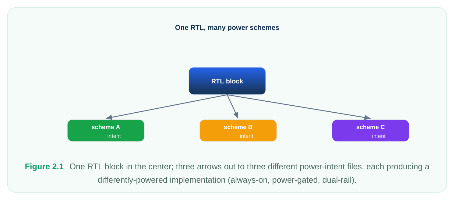
The functional behavior of the design lives in the RTL. The power architecture — which blocks have their own supply, which can be switched off, where isolation and level shifting are needed, which registers retain state — lives in a separate power-intent file. The RTL describes what the logic does. The power-intent file describes how the logic is powered. They are deliberately kept apart. Why does this matter so much? Consider a single RTL block, say a video decoder. One product wants to ship it always-on at a single voltage. A second product wants to power-gate it when idle. A third wants it on a separate, lower voltage rail with level shifters at its boundary. It is the same RTL in all three cases. Only the power architecture differs. If the power scheme were baked into the RTL, you would be forking and re-verifying the logic three times. By keeping power intent in a side-file, the one golden RTL targets three different power schemes by simply swapping the power-intent description.
Why a Side-File Instead of Embedding It in RTL
You could imagine encoding power behavior directly in HDL — adding always-on flags, isolation logic, retention modeling, and so on by hand. Designers tried versions of this for years, and it was a mess. Separating power intent into a dedicated, standardized file buys you four concrete advantages:
| Property | What it means in practice |
|---|---|
| Clean logic | The RTL stays purely functional and readable. No isolation gates, no retention plumbing, |
no rail tracking cluttering the design.
Portability The same RTL can be retargeted to a new power scheme by changing only the side-file
| Tool | Because the format is an open standard, synthesis, place-and-route, verification, and |
|---|---|
| independence | signoff all read the same intent. No translation, no drift. |
| Machine- | The intent is structured, not prose. Tools can formally verify that the implementation |
| checkable | matches the intent and that no rule (e.g., a missing isolation cell) was violated. |
That last point deserves emphasis. A power-intent file is executable specification. It is not documentation that a tired engineer reads and hopefully obeys. The tools consume it directly, so the gap between "what we meant" and "what got built" collapses. A power-aware verification tool can prove that every signal crossing from a switchable domain into an always-on domain passes through an isolation cell — because both the crossing and the isolation requirement are described in the same machine-readable source.
The Building-Block Vocabulary
The power-intent format gives you a compact, conceptual vocabulary. You are not describing transistors; you are describing a power network abstraction and the policies that govern it. The major building blocks:
- Supply ports, nets, and sets. A supply port is where power enters a scope (think of it as a pin for a rail). A supply net is the conductor that carries that rail through the design. A supply set is a convenient bundle that groups a power net and its associated ground net (and sometimes more) so you can refer to "a supply" as one named object rather than juggling individual nets.
- Power domains. A power domain is a region of logic that shares the same primary supply and is powered (and switched) as a unit. Domains are the fundamental partition of your design from a power standpoint.
- Power switches. A power switch is the abstract description of the gating device that connects (or disconnects) a switchable domain from its always-on rail, controlled by an enable signal.
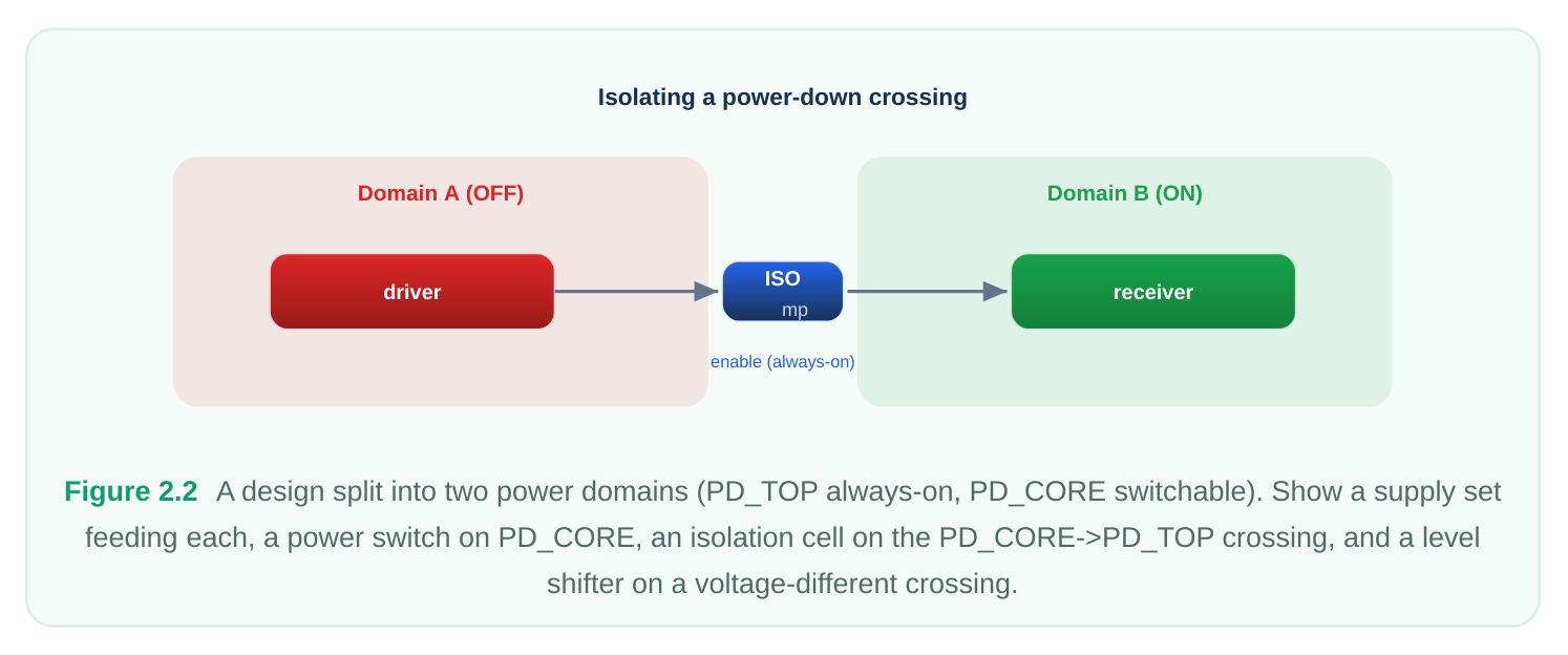
- Isolation strategies. A policy stating that signals leaving a domain that may power down must be clamped to a known, safe value so a powered-on neighbor never sees a floating input.
- Level-shifter strategies. A policy stating that signals crossing between domains at different voltages must pass through a voltage-translating cell.
- Retention strategies. A policy stating which sequential elements keep their state across a power- down using special retention storage on an always-on rail.
- Port attributes. Annotations on ports — for example, declaring a port as always-on, or specifying which supply a boundary pin is related to — that let tools reason correctly about connectivity and biasing. Notice the pattern: a few of these are structural (ports, nets, domains, switches) and the rest are policies (isolation, level shifting, retention). You build the network, then you state the rules that govern crossings and shutdowns. Tools turn those policies into actual cells. A useful mental model is that the structural commands describe a graph — supply ports are sources, supply nets are edges, domains are colored regions of that graph — while the policy commands describe guards on the edges that cross between regions. When a signal leaves a region that can lose power, an isolation guard applies. When a signal moves between regions at different voltages, a level- shift guard applies. When a sequential element inside a region must survive that region losing power, a retention guard applies. Thinking in terms of region boundaries and the guards required at each crossing is exactly how a power-aware tool reasons internally, and it is the fastest way to predict what cells a given intent file will cause to be inserted. If you can look at a domain partition and a set of strategies and immediately sketch where every special cell lands, you understand power intent at the level an interviewer is probing for.
A First Concrete Example
Let's make this tangible with standard commands. Suppose we have a top design with an always-on region and a switchable core. First we create the supply infrastructure: a port where the primary rail and ground arrive, and nets to carry them.
# Establish supply infrastructure at the current scope
create_supply_port  VDD     -domain PD_TOP
create_supply_port  VSS     -domain PD_TOP
create_supply_net   VDD     -domain PD_TOP
create_supply_net   VSS     -domain PD_TOP
# Connect the incoming ports onto the nets
connect_supply_net  VDD     -ports VDD
connect_supply_net  VSS     -ports VSS
Next we declare the two power domains. The top domain owns the chip-level logic; the core domain is the region we intend to switch off.
# Define the always-on top domain (the default scope of the design)
create_power_domain  PD_TOP
# Define a switchable domain over a sub-block instance
create_power_domain  PD_CORE -elements {u_core}
With domains in place, we describe the gating device and the policies. The power switch ties the switched supply of PD_CORE to the always-on rail under control of an enable. Isolation clamps the core's outputs while it is off; retention preserves selected registers.
# Gating device for the switchable domain
create_power_switch  sw_core \
-domain        PD_CORE \
-input_supply_port  {vin  VDD} \
-output_supply_port {vout VDD_CORE_SW} \
-control_port  {sleep   pwr_ctrl/sleep_n} \
-on_state      {ON  vin {!sleep}}
# Clamp PD_CORE outputs to 0 while it is powered down
set_isolation  iso_core \
-domain     PD_CORE \
-isolation_supply_set PD_TOP_ss \
-clamp_value 0 \
-applies_to  outputs
# Retain the core's control registers across power-down
set_retention  ret_core \
-domain     PD_CORE \
-retention_supply_set PD_TOP_ss \
-elements   {u_core/ctrl_regs}
These three commands are the heart of a power-gated design described in intent: what device switches the rail, what protects the boundary, and what survives the shutdown. The tool downstream is responsible for inserting the actual switch cells, isolation cells, and retention flops — but it does so because the intent told it to, and a verification tool can confirm it did so correctly.
Scope and Hierarchy: Where Intent Is Applied
Power intent is always interpreted relative to a current scope — a point in the design hierarchy that all subsequent commands are relative to, much like a current working directory in a filesystem. The
set_scope  command moves you around that hierarchy.
# Describe power intent down inside a sub-block, then return to top
set_scope  u_subsystem
create_power_domain  PD_SUB -elements {u_engine}
# ... domain-local supplies, switches, strategies ...
set_scope  ..             ;# pop back up one level
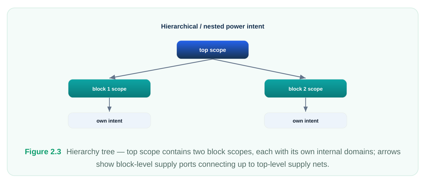
Why does scope matter? Because real designs are built from blocks and reused IP, and power intent composes hierarchically. A block-level team can write the power intent for their block — its internal domains, its boundary isolation requirements, its supply expectations — and ship that intent alongside the block. When the top-level team integrates the block, they connect the block's supply ports to toplevel rails and the block's internal intent is rolled up into the full-chip view. The block author and the integrator share the same standard, so the block's power contract travels with it. This mirrors how RTL itself composes: you instantiate a module and wire up its ports. Here you instantiate a block and connect its supplies and honor its power contract. The result is that a large SoC's complete power architecture is assembled from many smaller, independently-authored, independently-verified pieces of intent.
Golden Intent: One Source of Truth Across the Whole Flow
The phrase you will hear constantly is "golden power intent." It captures the central promise of the standard: a single authoritative power-intent description flows through the entire implementation and verification flow, and every tool obeys it.
| Flow stage | What the power intent drives |
|---|---|
| RTL / | Power-aware simulation: domains power down, isolation clamps activate, non-retained |
| simulation | state corrupts on shutdown — exposing functional bugs early. |
| Synthesis | Mapping logic into domains; inserting isolation, level-shifter, and retention cells; honoring |
always-on constraints.
Placement Physical grouping of domains; placement of switches and special cells; respecting
Routing Building the supply network — rails, switch fabric, always-on routing — consistent with
| Signoff / | Formally checking that the implementation matches intent: no missing isolation, no illegal |
|---|---|
| verification | crossings, correct retention, consistent supplies. |
The win is consistency. Because all stages read the same file, the isolation cell that simulation assumed, that synthesis inserted, that placement positioned, and that signoff checked are all the same cell governed by the same policy. There is no opportunity for the routing tool's understanding of the power architecture to silently diverge from the synthesis tool's understanding. The intent is golden precisely because it is singular and shared.
Incomplete Intent and Successive Refinement
A subtle but important capability: power intent does not have to be written all at once, fully detailed, on day one. The standard supports successive refinement — a high-level, deliberately incomplete constraint file authored early, then enriched with implementation detail later. In the early architectural phase, an IP or block team may capture only the constraints: "this block contains these domains, signals on this boundary must be isolated, these supplies are expected." This is constraint-level intent. It is enough to verify the architecture and to communicate the power contract — but it intentionally omits implementation specifics like exactly which supply set powers the isolation cells or which physical switch is used. Later, during implementation, that constraint file is refined: the abstract supply sets are bound to real nets, isolation strategies get concrete supplies and locations, switches get real control connectivity. The early intent is not thrown away and rewritten — it is extended. The constraints written upstream remain in force and are checked against the refined detail, so an implementation choice that violates an early architectural constraint is caught.
# --- Constraint phase: high-level, implementation-agnostic ---
create_power_domain  PD_CORE -elements {u_core}
set_isolation  iso_core -domain PD_CORE -applies_to outputs -clamp_value 0
# (no isolation supply bound yet — just the requirement)
# --- Refinement phase (later file): add implementation detail ---
set_isolation  iso_core -domain PD_CORE \
-isolation_supply_set PD_TOP_ss   ;# now bind the real supply
set_isolation_control  iso_core -domain PD_CORE \
-isolation_signal pwr_ctrl/iso_en -isolation_sense high
This two-phase style is how real projects manage the reality that architecture is decided before all physical details are known. The early file lets architects lock the power contract and verify intent before implementation exists; the later file completes the picture without disturbing what was already agreed. It is the power-intent analog of writing an interface specification first and the implementation second.
Common Pitfalls When Authoring Power Intent
Because the intent is executable, mistakes in it produce real, sometimes subtle, failures. A handful of errors recur often enough to be worth memorizing, and they make excellent interview discussion points.
| Pitfall | Why it bites | Better practice |
|---|---|---|
| Wrong current | Commands silently apply to the wrong | Always pair set_scope with an |
| scope | level of hierarchy; a domain meant for a sub-block lands at top. | explicit return ( set_scope .. ); keep block intent in its own file. |
| Missing isolation on | An output of a powered-down domain | Define isolation policies for all outputs of |
| a crossing | floats into a live domain, propagating X or oscillation. | every switchable domain, not just the ones that "seem important." |
| Isolation/retention | The protective cell itself loses power | Bind isolation and retention to an |
| cell on the wrong | when the domain shuts off, defeating its | always-on supply set, never to the |
| supply | purpose. | switchable rail. |
| Implicit voltage | A crossing between two rails at different | Declare level-shifter strategies on every |
| assumptions | voltages without a level-shift policy yields a functional or reliability failure in silicon. | cross-voltage boundary; do not rely on defaults. |
| Constraint and | A late implementation detail quietly | Keep both files in the flow so the tool |
| refinement disagree | contradicts an early architectural constraint. | checks refinement against constraint and flags the conflict. |
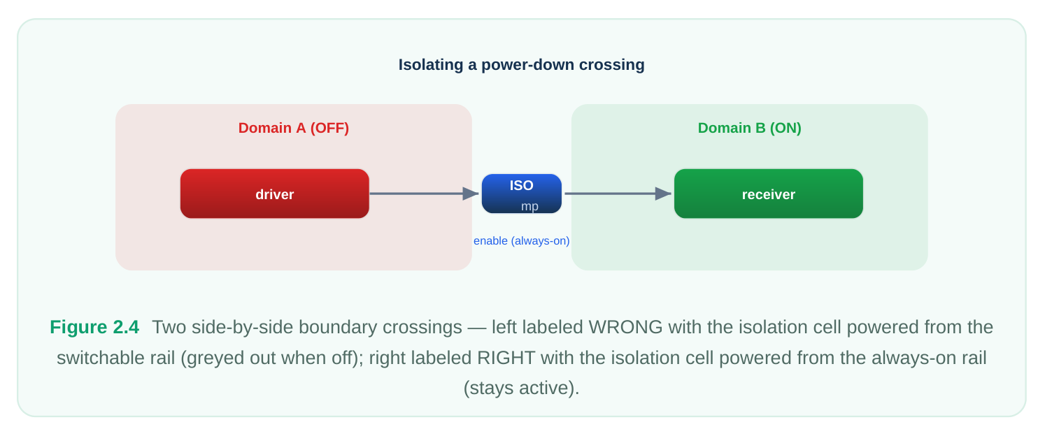
The unifying theme is that isolation and retention cells must themselves stay powered. This is the single most common conceptual mistake newcomers make: they correctly place an isolation cell on the boundary but power it from the domain that is being shut off, so the clamp dies exactly when it is
needed. Whenever you write a set_isolation or set_retention , the very next thing you should ask is "and what keeps this cell alive?" The answer is almost always an always-on supply set.
Interview Q&A
Separation keeps the RTL purely functional, readable, and reusable. The same golden RTL can target different power schemes — always-on, power-gated, multi-rail — by swapping the power-intent sidefile, with no logic edits and no re-verification of function. Because the format is an open standard, every tool in the flow reads the identical intent, eliminating translation and drift, and because it is structured rather than prose, tools can formally check that the implementation matches the intent.
is the boundary point where a rail enters a scope — conceptually a pin for power. A supply net is the conductor that carries that rail through the design. A supply set is a named bundle grouping related supplies (typically a power net and its ground) so you can reference "a supply" as a single object in strategies, rather than tracking individual nets. Ports and nets are the wiring; the supply set is a convenient handle over them.
authoritative power-intent description that flows through simulation, synthesis, placement, routing, and signoff, and every tool obeys it. It matters because it guarantees consistency: the isolation, levelshifter, and retention cells that simulation assumes, synthesis inserts, placement positions, and signoff verifies are all governed by the same policies from the same file. There is no chance for one tool's view of the power architecture to silently diverge from another's.
power-intent file? Successive refinement is authoring high-level power constraints early — domains, boundary isolation requirements, expected supplies — without committing to implementation specifics, then extending that file later with concrete detail (real supply bindings, control signals, switch connectivity). You use the constraint-level file during the architecture phase to lock and verify the power contract before implementation exists; the upstream constraints stay in force and are checked
against the refined detail, so any later implementation choice that violates an early architectural decision is caught.
Key Takeaways
- Power architecture is described separately from RTL in the power-intent (UPF / IEEE 1801) file: RTL says what the logic does; the intent says how it is powered.
- A side-file gives four wins: clean logic, portability, tool independence, and machine- checkability — the intent is executable specification, not documentation.
- The vocabulary splits into structure (supply ports/nets/sets, power domains, power switches) and policy (isolation, level-shifter, and retention strategies), plus port attributes.
- Intent is applied relative to a current scope and composes hierarchically, so block-level intent travels with reusable IP and rolls up into the top-level view.
- Golden intent is one authoritative description shared by every flow stage from simulation through signoff, guaranteeing consistency.
- Successive refinement lets you write high-level constraints early and add implementation detail later, with the early constraints continuously enforced.
Comments
Leave a Reply