 ChipBuddy
← Home
ChipBuddy
← Home
Power Domains and the Supply Network
Power Domains and the Supply Network
In the previous chapters we treated low power as a set of techniques: clock gating, multiple voltage thresholds, power gating, and voltage scaling. This chapter is where those techniques acquire a structure. A modern low-power chip is not a single sea of logic running off one rail. It is a collection of regions, each with its own rules about whether it is powered, at what voltage, and when. The vocabulary we use to describe those regions — and the wires that feed them — is the subject of this chapter. Once you understand power domains and the supply network beneath them, the rest of multivoltage design (isolation, level shifting, retention, state tables) becomes a set of consequences rather than a list of disconnected rules. This is also the part of the interview where vague answers get exposed. Anyone can say "we partition the chip into domains." The strong candidate can explain what a domain actually is, how supply nets bind to it, what a supply set abstracts, and why an unbound or floating supply will sink a design.
What a Power Domain Actually Is
A power domain is a group of logic instances that share the same primary supply and the same power behavior. "Same power behavior" is the operative phrase. Every instance inside a domain turns on together, turns off together, and scales its voltage together. The domain is the unit of power control.
You do not power-gate a single flop; you power-gate a domain. You do not scale the voltage of one adder; you scale the domain that contains it. Why partition a chip into domains at all? Because different blocks have different duty cycles and different performance needs. A radio receiver might be idle 95% of the time — there is no reason to leak current through it while the user is doing nothing. A security block may need to stay alive across deep sleep to watch for a wake event, while everything around it goes dark. A graphics core may need to run at a high voltage for performance, while an always-listening audio path can crawl along at a much lower voltage to save energy. Each of these is a distinct power requirement, and each becomes a domain.
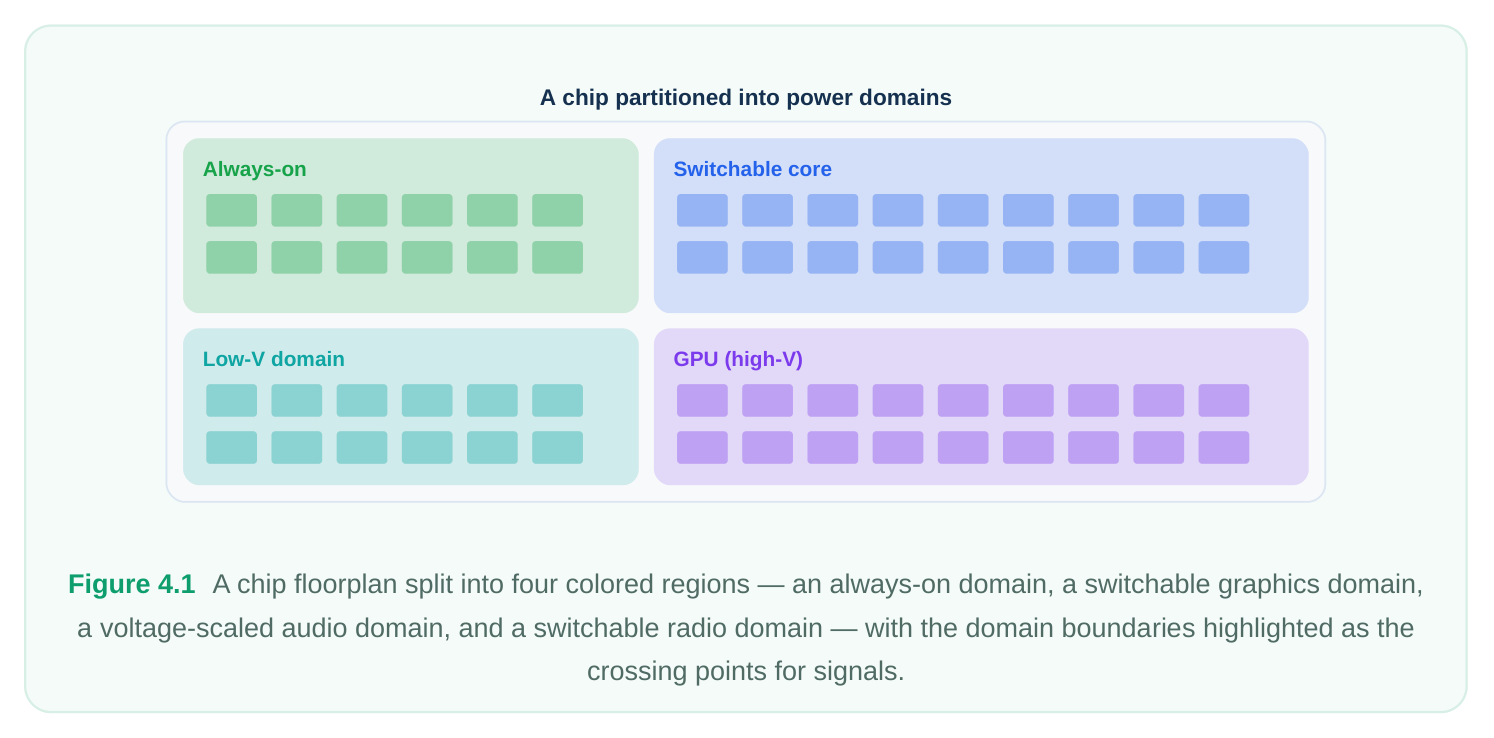
The key mental shift is this: a domain is a power concept, not necessarily a physical or hierarchical one. It usually maps onto a region of the floorplan, and it usually corresponds to one or more levels of the logical hierarchy, but the defining property is shared supply and shared behavior — not the netlist tree.
The Supply Hierarchy, Bottom-Up
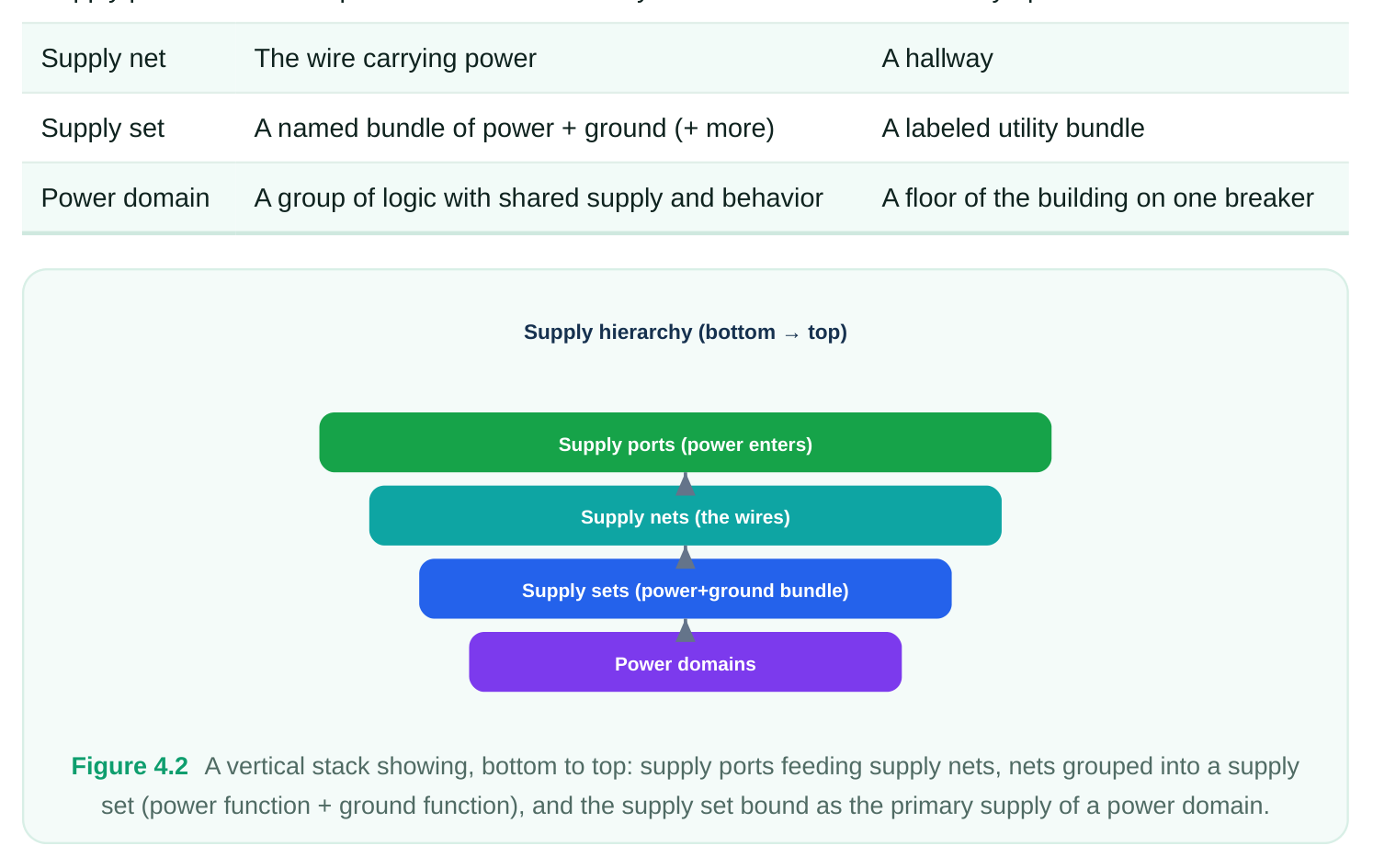
To reason about domains precisely, you need to understand how power physically reaches the logic. The power-intent standard (IEEE 1801, commonly called UPF) describes this with a small set of objects. We will build them up from the bottom. Supply ports are where power enters a scope. Think of a supply port as the pin on a block through which current arrives. A port is a boundary object: it represents the place where a supply crosses into (or out of) a region of the design. At the top level, supply ports correspond to the actual package pins or pads that connect to the board's regulators. Supply nets are the wires that carry power from a port to wherever it is consumed. If a supply port is the doorway, the supply net is the hallway. Nets are routed through the design, connecting ports to
cells and to other ports across hierarchy. A single net such as a ground reference may span the entire chip; a switched supply net may exist only inside one domain. Supply sets sit one level of abstraction above nets. A supply set is a bundle of related power functions — at minimum a power function and a ground function — grouped under one name. Instead of saying "connect this cell to net VDD_CORE and net VSS ," you say "this logic runs off supply set core_ss ," and the set internally knows which net plays the role of power and which plays the role of ground. Supply sets are powerful because they let you describe intent ("this block needs a power and ground pair") before you have committed to the exact nets that will implement it. The roles inside a supply set are usually named generically: a primary power function and a primary ground function, with the option to add more functions (for example, a separate well-bias function or a backup/retention function). Each function is eventually bound to a real supply net. Finally, all of this binds to domains. Every power domain has a primary supply set — the supply that feeds the ordinary logic in that domain. When you create a domain, you either give it a supply set directly or you create the set and associate it afterward. This binding is what makes the domain real: it is the link between "this group of logic" and "this is how power reaches it."
| Object | What it represents | Analogy |
|---|---|---|
| Supply port | Where power crosses a boundary | A doorway / pin |
Atomic vs Hierarchical Domains
Domains can nest. An atomic domain is a leaf: it contains logic but no sub-domains. A hierarchical domain contains other domains within its scope. This matters because a child domain inherits its
surroundings — it lives inside the supply environment of its parent and crosses that parent's boundary when it talks to the outside world. A common arrangement is a large parent domain that holds the bulk of the system, with smaller child domains carved out for blocks that need independent power control. The child can be switched off while the parent stays on, but the child's signals to the parent must still be handled at the boundary between them. Nesting is not free: every domain boundary you create is a place where crossing signals may need protection.
Always-On, Shutdown, and Switchable Domains
Three categories of domain show up constantly, and you should be able to name them on demand. An always-on (AON) domain is never powered down during normal operation. It holds the logic that must survive every sleep state: power-management controllers, isolation control logic, retention control, wake detection, and the supply-switch enable signals themselves. A critical and frequently tested point: the control logic that turns other domains off cannot itself be in a domain that gets turned off. If you power-gate your own power controller, nothing can ever wake it back up. The always-on domain is the anchor of the whole power architecture. A switchable (or shutdown) domain is one whose primary supply can be disconnected, collapsing the logic to zero (or near-zero) voltage to eliminate both dynamic and leakage power. These are the domains you carve out specifically to save energy when a block is idle. They are fed not by a raw supply but through a switch — conceptually a header or footer device controlled by an enable from the always-on domain. Powered during
Domain type Typical contents
Always-on Always PMU, isolation/retention control, wake logic, switch
Switchable / No — collapses to off Idle accelerators, radios, idle compute cores
Voltage-scaled Yes, but at a reduced Performance-flexible blocks (graphics, audio) Note that "switchable" and "voltage-scaled" are not mutually exclusive. A domain can be both switchable and capable of running at more than one voltage; what defines it is the set of power states it can occupy, which we formalize later with state tables.
Domain Boundaries: The Crossing Points
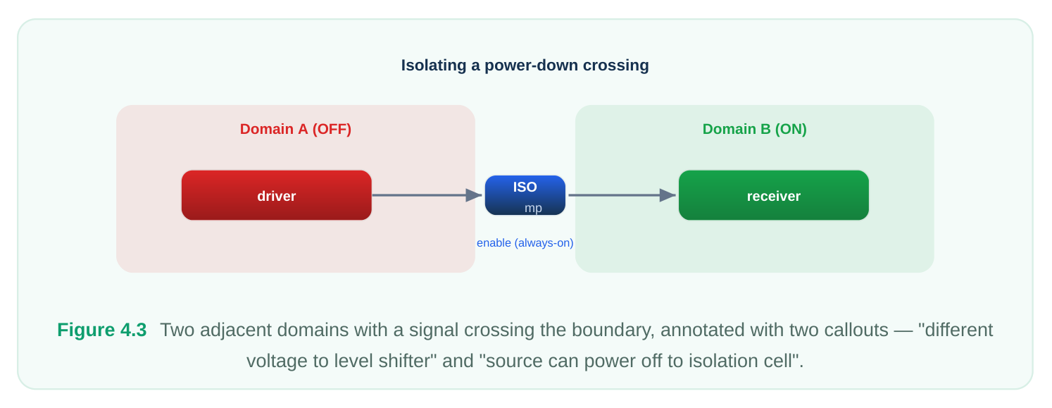
Here is the single most important reason domains are worth understanding carefully: every signal that crosses a domain boundary is a potential hazard. Two domains can differ in voltage, in on/off state, or in both. A signal leaving one domain and entering another may therefore arrive at the wrong
logic level, or it may originate from a block that is currently powered off and floating to an unknown value. These two problems map onto the two protection cells you will study in depth in later chapters:
- When the source and destination run at different voltages, the crossing signal needs a level shifter to translate the logic level.
- When the source domain can be powered off while the destination stays on, the crossing signal needs an isolation cell to clamp it to a known, safe value so the live domain never sees a floating input. For now, the lesson is structural rather than procedural: the boundary is where the action is. When you draw a domain, you are implicitly declaring a fence, and every wire that jumps that fence is a contract you must honor. A signal that crosses two domains unprotected is one of the classic ways a multivoltage design fails — sometimes silently in simulation, then catastrophically in silicon.
Primary vs Secondary Power, and How Cells Get Fed
Ordinary standard cells in a domain draw from the domain's primary supply — the power and ground delivered by the domain's primary supply set. In a clean flow you rarely connect each cell's power pins by hand; the cells inherit the primary supply of the domain they sit in. That inheritance is precisely why the supply set is bound to the domain: it tells every cell in the region where its power comes from without per-instance wiring. Some cells, however, need secondary power — a supply in addition to the primary one. The textbook examples are the special cells that live at domain boundaries and during power-down:
- An isolation cell must keep clamping even when the domain it protects is off, so it draws from an always-on supply rather than the (possibly collapsed) primary supply.
- A retention flop keeps a backup of its state alive on a secondary "retention" supply while its main logic supply is gone.
- A level shifter spanning two voltages needs access to both the source-side and destination-side rails.
This is the practical reason supply sets allow more than just one power and one ground function. The extra functions exist so that a cell can declare, "feed my main logic from the primary supply, but feed my keeper/clamp from this always-on supply." Getting secondary power right is a recurring source of bugs: an isolation cell accidentally tied only to the supply it is supposed to survive will not survive at all.
Refining Abstract Supply Sets and Binding Them Late
One of the most elegant features of the power-intent model is that you do not have to know the final supply implementation up front. You can create a supply set as an abstract handle, attach it to a domain, and design against it — then refine it later by binding its functions to concrete nets. This is sometimes called late binding. Why is this useful? Because power architecture is decided top-down but implemented bottom-up. Early in the project, you know that "the graphics block has its own switchable supply" long before you know the exact net names, the switch cells, or how the rail is routed. Abstract supply sets let you capture that intent immediately and commit to the wiring when the floorplan is mature. It also makes IP reuse cleaner: a block can be delivered with abstract supply sets that the integrator binds to the real chip-level supplies, without editing the block's internals. The discipline that matters here is completeness. An abstract supply set is a promise that real nets will be bound to its functions. If you forget to keep that promise, you have an unbound supply set — a domain that claims to have power but never says where it comes from. That is one of the most common fatal errors in a power-intent file, and we return to it below.
Worked Conceptual Example: Building Two Domains
Let us make this concrete. Suppose a design has a top level containing two blocks: a control block that must always be on, and a compute block that we want to be switchable. We will create an alwayson domain and a switchable domain, give each a supply, and wire them up using the standard powerintent commands. The names below are illustrative. First, define the top scope's supply entry points and the nets that carry power. The supply port is where power enters; the supply net is the wire.
# --- Top-level supply entry and global rails ---
create_supply_port  VDD_TOP -domain top_pd
create_supply_port  VSS     -domain top_pd
create_supply_net   VDD_TOP -domain top_pd
create_supply_net   VSS     -domain top_pd
# Bind the entering power at the port to the net that distributes it
connect_supply_net  VDD_TOP -ports VDD_TOP
connect_supply_net  VSS     -ports VSS
Next, create the two domains. The always-on domain holds the control logic; the switchable domain holds the compute block. Each domain is given the set of instances it owns.
# --- Power domains ---
# Always-on domain: control / power management lives here
create_power_domain  aon_pd  -elements {u_control u_pmu}
# Switchable domain: compute block, can be powered down
create_power_domain  sw_pd   -elements {u_compute}
Now describe the supplies as supply sets — abstract bundles of a power function and a ground function — and bind their functions to real nets. The always-on domain runs off the global rail. The switchable domain runs off a switched version of that rail, which a power switch will gate.
# --- Supply sets bound to domains ---
# Always-on domain uses the global, never-gated rail
create_supply_set aon_ss \
-function {power VDD_TOP} \
-function {ground VSS}
# A switched net for the compute domain (gated by a switch elsewhere)
create_supply_net VDD_SW -domain sw_pd
create_supply_set sw_ss \
-function {power VDD_SW} \
-function {ground VSS}
Finally, declare which supply set is the primary supply of each domain. This is the binding that makes the domains real — every cell inside aon_pd now inherits aon_ss , and every cell inside sw_pd inherits sw_ss .
# --- Associate primary supplies with their domains ---
associate_supply_set aon_ss -handle aon_pd.primary
associate_supply_set sw_ss  -handle sw_pd.primary
# Distribute the always-on rail down to where it is needed
connect_supply_net VDD_TOP -domain aon_pd
connect_supply_net VSS     -domain aon_pd
connect_supply_net VSS     -domain sw_pd
At this point we have two domains. The control domain is permanently fed by VDD_TOP . The compute domain is fed by VDD_SW , a switched net that can be collapsed to save power. Notice what is not yet handled: the signals from u_compute into u_control . When sw_pd powers down, those signals will float, and the live aon_pd will see garbage unless they are isolated. That protection — isolation at this boundary, and level shifting if the two rails differ in voltage — is the natural next step, and it follows directly from the boundary we just created.
Common Mistakes
Three failure modes account for a large share of real power-intent bugs, and all three are favorites with interviewers. Floating supplies. A supply net that is created but never connected to a port (or to the supply it is meant to carry) is floating — it has no defined source. Logic associated with it has, in effect, no power. This often slips through because the file looks complete: the net exists, the domain references it, but nothing drives it. The fix is discipline: every net should trace back through a connect_supply_net to a real port or switched source. Unbound supply sets. An abstract supply set whose functions are never refined to concrete nets is a promise unkept. The domain claims to have a primary supply, but that supply resolves to nothing. Tools will flag this, but only if you read the warnings — and these warnings are easy to drown in a noisy log. Treat any "unresolved" or "unbound" supply message as a hard error, not a nuisance. Signals crossing domains unprotected. This is the most consequential of the three. A wire that leaves a domain which can power down, and enters a domain that stays on, must be isolated; a wire crossing a voltage boundary must be level-shifted. Skipping this does not always break in functional simulation, because simulation may not model the off domain's floating value correctly. It breaks in silicon, intermittently, in the field — the worst possible place to find it. The structural habit that prevents it is simple: whenever you create a domain boundary, immediately ask of every crossing signal, "different voltage? source can turn off?" and protect accordingly.
Interview Q&A
net is a concrete wire that carries one power or ground signal. A supply set is an abstraction that bundles related functions — at least a power and a ground — under one name, where each function is eventually bound to a net. You want both because the set lets you express intent ("this block needs a power/ground pair") and bind cells to a domain by inheritance, while the nets handle the physical reality of routing. The set also enables late binding and IP reuse: you design against the abstract set and refine it to real nets when the implementation is settled.
controller that issues shutdown and wake-up commands is itself in a switchable domain, powering that domain off would also kill the controller — and there would be nothing left alive to ever turn it back on. The power-management logic, isolation and retention control, and the switch enable signals must reside in a domain that is never gated, so the system always retains the ability to sequence other domains on and off.
voltage. What protection does it need and why? It needs an isolation cell, not a level shifter. The voltages match, so no level translation is required, but the source can collapse to off, leaving its output floating. The always-on destination would then sample an undefined value, which can cause functional failure or crowbar current. An isolation cell clamps the signal to a known value (high, low, or held) while
the source is down. Note the isolation cell itself must draw from an always-on supply so it keeps clamping after the source dies.
even though a supply set is associated with it. Where do you look? Two prime suspects. First, an unbound supply set: the set is associated with the domain but its power and/or ground functions were never refined to real nets, so it resolves to nothing. Second, a floating supply net: a net exists and is referenced but was never connected to a port or switched source via connect_supply_net , so it has no driver. Both produce "logic with no real power" while the file superficially looks complete. Check the tool's unresolved/unbound supply warnings, then trace each function and net back to a concrete, driven source.
Key Takeaways
- A power domain is a group of logic sharing one primary supply and one power behavior (on, off, scaled). It is the unit of power control — you gate and scale domains, not individual cells.
- The supply hierarchy, bottom-up: supply ports (where power enters) feed supply nets (the wires), which are grouped into supply sets (named power+ground bundles), which bind to domains as their primary supply.
- Domains can be atomic or hierarchical, and are commonly classified as always-on, switchable/ shutdown, or voltage-scaled. The always-on domain anchors all power control and must never be gated.
- Every domain boundary is a hazard point: voltage differences demand level shifters, power-down sources demand isolation cells.
- Primary power feeds ordinary cells by inheritance; secondary/always-on power keeps isolation cells, retention flops, and level shifters alive across power-down.
- Abstract supply sets let you capture intent early and bind nets late, but the promise must be kept — and the three classic killers are floating supplies, unbound supply sets, and unprotected
cross-domain signals.
Comments
Leave a Reply