 ChipBuddy
← Home
ChipBuddy
← Home
Synthesizing & Inserting Power-Management Cells
Chapter 13 — Synthesizing & Inserting Power-Management Cells
Power intent written in the standard format (IEEE 1801, commonly called UPF) is a specification, not an implementation. It says, in effect, "an isolation clamp must guard every signal leaving this domain when its supply collapses," or "this register bank must keep its state across power-down." It does not place a single transistor. Turning that specification into real silicon is the job of the implementation tool, and the step that does it is the automatic synthesis and insertion of power-management (PM) cells — isolation, level-shifter, retention, always-on buffer, and power-switch cells. This chapter is about how that machinery works, where it gets things right on its own, and where you, the designer, must intervene. Think of the power intent as a contract and the PM cells as the physical clauses that enforce it. The tool reads the contract, finds every place a clause is required, selects a matching component from the technology library, drops it into the netlist, wires its control and supply pins correctly, and gives it a predictable name. When the library has no part that satisfies a clause, the contract is breached — and the tool must flag it rather than silently ignore it.
Realizing intent: PM-cell insertion
| Power intent | Match library | Insert & place | Tie controls & | Re-verify |
|---|---|---|---|---|
| (strategies) | PM cells | cells | supplies |
Figure 13.1 Flow from power intent (strategies) → matching against library PM cells → insertion into netlist →
control/supply tie-off → verification
From Strategy to Silicon: What Gets Inserted Where
Every power-intent command that asks for protection or continuity maps to a specific class of physical cell. Understanding the mapping is the foundation; everything else is mechanics. Power-intent
Inserted cell type Purpose Key connections
| Isolation on domain | Isolation cell (clamp AND/ | Hold a stable value on a | Enable (isolation control), |
|---|---|---|---|
| outputs | OR/latch) | signal whose driving domain is off | clamp value, always-on supply |
| Voltage crossing | Level shifter | Translate logic levels | Both source and |
| (low→high or | (unidirectional / high→low) | between domains at bidirectional / enabled) | destination supplies different voltages |
| State retention | Retention register / retention controller cell | Preserve flop state during power-down | Save/restore controls, always-on backup supply |
| Always-on path | Always-on buffer / | Keep a net live where the | Continuous (un-gated) |
| through a switched | feedthrough | surrounding logic is gated | supply |
domain
| Power gating | Power switch (header / | Connect or disconnect a | Switch enable(s), true and |
|---|---|---|---|
| footer) | domain's switched rail | switched supply rails | |
| Constant tie in a | Always-on tie-high / tie- gated domain | Provide a logic constant low cell | Always-on supply that survives domain |
shutdown A useful mental discipline: isolation protects the receiver from a floating or unknown input; level shifting protects signal integrity across a voltage boundary; retention protects state; always-on cells protect continuity; power switches create the savings the rest is protecting. When you read an insertion report, classify each cell into one of those five buckets and the netlist suddenly becomes legible.
Voltage-Aware Optimization
The most common mistake a non-power-aware tool would make is to treat the whole design as a single voltage island and pick cell drive strengths accordingly. A power-aware implementation flow instead knows the operating voltage of each domain and optimizes per domain. Two failure modes matter. Over-driving happens when a cell sized for a high-voltage domain feeds a low-voltage domain — it burns power and may overstress the receiver. Under-driving is the reverse: a weak low-voltage driver cannot meet timing into a high-voltage load, or its output never cleanly reaches the receiver's threshold. Voltage-aware optimization picks the right library variant (each library is characterized at a specific voltage corner) and the right drive strength for the local domain, and it inserts a level shifter precisely at the boundary rather than hoping a stretched buffer can bridge the gap. The practical consequence: the tool must associate each cell instance with its domain and supply before it sizes anything. A correct flow never moves a cell across a power boundary during optimization without re-evaluating its supply legality. That is why you load the power intent before, not after, the main optimization passes.
Insertion Mechanics: Picking, Naming, Placing, Tying
Insertion is a four-part operation repeated for every required PM cell.
- 1. Pick the library cell. The tool searches the technology libraries for cells carrying the right power-
management attribute — a cell marked as an isolation cell, a level shifter, a retention flop, and so on. Among candidates it filters by the clamp/translation behavior the strategy demands (e.g., a clamp-to-0 isolation cell vs. clamp-to-1), then by the voltages involved, then by timing and area cost.
- 2. Name the cell. Inserted cells get systematic, prefix-based names so they are recognizable in
reports, constraints, and ECOs. A consistent naming scheme also lets downstream steps find every PM cell by pattern.
- 3. Place the cell. Location matters enormously. Isolation cells generally belong in the always-on
region near the domain boundary so their logic survives when the protected domain dies. Level shifters straddle the boundary. Switches form rows or a grid. Retention cells replace ordinary flops in place.
- 4. Tie controls and supplies. Each inserted cell needs its enable/control nets connected to the
correct power-control signals, and — critically — its supply pins connected to the correct rails. An isolation cell powered by the very domain it is protecting is worthless; it must sit on an always-on supply.
# Realize all power-intent strategies into the netlist.
# The tool reads the loaded power intent and inserts the
# matching PM cells, placing and tying them automatically.
insert_pm_cells \
-isolation \
-level_shifter \
-retention \
-enable_supply_check true
# Inspect what was inserted, grouped by strategy and domain.
report_pm_cells -by_strategy -columns {cell_type lib_cell domain supply}
Mapping: Binding Strategies to Real Library Cells
It is useful to separate two sub-steps that the tool performs. Insertion decides that a cell is needed and where it goes. Mapping binds that need to a concrete library cell. Some flows expose these separately so you can insert generic placeholders first (fast, technology-independent) and bind them to real cells later, after the right libraries are loaded.
# Bind inserted, still-generic PM cells to concrete library cells.
map_pm_cells \
-respect_voltage true \
-prefer_low_leakage true
# Confirm every PM cell now references a real library cell;
# anything still generic is an "unmapped" cell to resolve.
report_pm_cells -unmapped
This split is also where unmapped power-management cells appear: intent that the library cannot satisfy. If the power intent asks for an enabled level shifter from 0.6 V to 1.0 V but the libraries only contain a plain (non-enabled) level shifter at those voltages, mapping fails for that crossing. The cell stays generic and is reported as unmapped. Resolutions, in order of preference:
- 1. Load the missing library. Often the right cell exists in a kit that simply was not referenced.
- 2. Relax the strategy to a behavior the library does support (e.g., drop the enable requirement if the
protocol allows).
- 3. Substitute a different but equivalent cell class the library offers.
- 4. Provide a manual instance and tell the tool not to touch it.
Never ship a design with unmapped PM cells. An unmapped isolation clamp is an unprotected boundary; an unmapped shifter is a broken voltage crossing.
Merging and Cloning for Area and Fanout
Automatic insertion is deliberately conservative — it guarantees correctness first. That can leave redundancy on the table, and two optimizations clean it up.
Merging combines multiple PM cells that do identical work. If three signals cross the same domain boundary in the same direction with the same enable, three separate isolation cells may collapse logic where legal, or several shifters sharing a source/destination pair may be consolidated. The classic case is many isolation cells driven by one common enable: their control trees merge even when the data cells cannot. Merging saves area and leakage. Cloning is the opposite move, applied for electrical reasons. A single isolation or always-on cell feeding a huge fanout, or feeding loads scattered far across the floorplan, becomes a timing and reliability liability. Cloning duplicates the cell so each copy drives a local, manageable load. You trade a little area for closure.
| Operation | When to apply | Benefit | Risk if overused |
|---|---|---|---|
| Merge | Redundant cells, shared enable, same crossing | Area and leakage reduction | Concentrated fanout, hotspots |
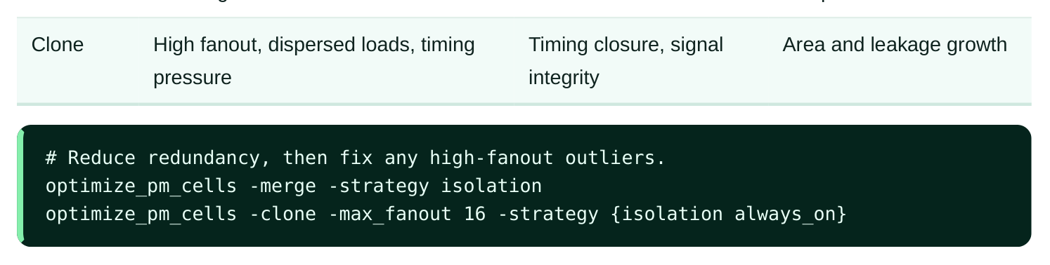
Treat these as a balanced pair: merge globally for area, then clone selectively where merging (or the original insertion) created a fanout problem.
Suppressing and Constraining Automatic Insertion
Automation is the default, not a mandate. There are legitimate reasons to take manual control: a handcrafted boundary cell that must not be disturbed, a third-party block delivered with its PM cells already placed, or a corner case where you do not trust the tool's choice. The flow gives you graduated control.
- Exclude a region or boundary from automatic insertion so you can place cells yourself.
- Pin a specific library cell for a given strategy so the tool stops searching.
- Mark an existing instance as designer-managed so optimization, merging, and cloning leave it alone.
- Disable a whole strategy class if you are handling it in another step.
# Hands off this boundary; I will place these cells manually.
set_pm_cell_insertion -strategy isolation \
-boundary U_secure_core -mode manual
# For level shifters at this crossing, use exactly this cell.
set_pm_cell_mapping -strategy level_shifter \
-from PD_lo -to PD_hi -lib_cell LS_ENABLED_06_10
# Protect a manually placed instance from later optimization.
set_dont_touch [get_pm_cells U_iso_handcrafted]
The principle: constrain narrowly. Suppress insertion for the one boundary you own, not for the whole design — broad suppression quietly reintroduces every protection bug automatic insertion was created to prevent.
Tie Cells in Gated Domains
Ordinary tie-high and tie-low cells provide logic constants. In a domain that can power down, a normal tie cell sourced from the switched rail goes dark with the domain — and any always-on logic depending on that constant sees an unknown. The fix is an always-on tie cell, powered from a continuous supply, so the constant survives shutdown. Two correction actions are common. First, when the tool inserts tie cells in a gated domain, it should automatically choose the always-on variant for any constant feeding always-on logic. Second, during cleanup you may find legacy or wrongly-sourced tie cells; power correction on tie cells rewires them to the proper always-on rail or swaps them for the correct variant.
# Audit tie cells whose constants must outlive domain shutdown,
# then correct their supply to an always-on rail.
report_pm_cells -strategy tie -domain PD_switched
correct_pm_cell_power -strategy tie -use_always_on true
Hierarchical Handling: Macros, Black Boxes, and Abstracts
Real chips are hierarchical, and large parts of them are opaque to the implementation tool: hard macros, memories, analog blocks, and IP delivered as black boxes. The tool cannot insert cells inside these, so it relies on abstracted models — a compact description of the block's boundary that declares each port's voltage, its power domain, whether it is always-on, and what isolation or shifting the parent must provide. This abstraction is what makes top-level insertion possible without flattening everything. The parent reads the block's boundary model, sees (for example) that a memory's output port is in a switched domain, and inserts isolation on the parent side of that port. The discipline that makes this work:
- Every black box must carry a boundary power model; a missing model means the tool guesses, and it will guess wrong.
- Port voltages and domain associations on the abstract must match what the block was actually built with.
- Isolation and level shifting are inserted on the parent side of an opaque block; you cannot reach inside it.
- Always-on ports on the macro must be fed from genuinely always-on parent nets, verified end to end.
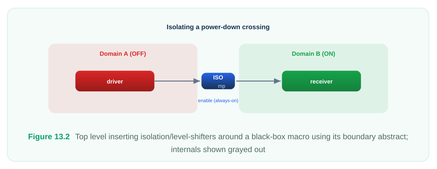
The most common hierarchical bug is a mismatch between the abstract and reality — the model says a port is always-on but the block actually gates it, or vice versa. Insertion then "succeeds" against a false contract, and the error surfaces only in power-aware verification or silicon. Trust, but verify the abstract.
Putting It Together: A Sane Order of Operations
- 1. Load libraries and the complete power intent first.
- 2. Run automatic insertion for all required strategies.
- 3. Map generic cells to real library cells; resolve every unmapped cell.
- 4. Merge for area, then clone to fix fanout outliers.
- 5. Correct tie-cell and other supply issues in gated domains.
- 6. Apply targeted manual overrides only where you genuinely own the boundary.
- 7. Report and verify: zero unmapped cells, every PM cell on a legal supply, every boundary protected.
# Final gate: no unmapped cells, no illegal supplies.
report_pm_cells -unmapped
report_pm_cells -supply_check -only_violations
Interview Q&A
protects? Because its job is to hold a defined value on a signal while the protected domain is off. If it were powered by that same switched domain, it would lose power at exactly the moment it is needed,
and the boundary would float into the receiving always-on logic. The isolation cell — and the enable controlling it — must live on a supply that remains up across the shutdown, which is why insertion places these cells in the always-on region and ties their supply pins to the continuous rail.
the tool knows is required by the power intent but for which it could not find a matching library cell — for instance, an enabled level shifter at a specific voltage pair that the loaded libraries do not contain. The cell remains generic and is flagged. Resolve it by loading the missing library, relaxing the strategy to a supported behavior, substituting an equivalent cell class, or supplying a manual instance and marking it designer-managed. Shipping with unmapped PM cells means shipping unprotected boundaries.
Cloning duplicates a cell to split a load — used when one isolation or always-on cell drives too large or too dispersed a fanout to meet timing or maintain signal integrity. Merging is the inverse: it combines redundant cells doing identical work (same crossing, same enable) to save area and leakage. The typical flow merges globally for area, then clones selectively where fanout has become a problem. Over-merging causes hotspots; over-cloning wastes area and leakage.
macro's abstracted boundary power model, which declares each port's voltage, domain, and alwayson status. From that, the tool inserts the needed isolation and level-shifter cells on the parent side of the boundary — it cannot reach inside the macro. The correctness of this hinges entirely on the abstract matching the block's real construction; a wrong always-on or domain attribute on a port leads insertion to satisfy a false contract, and the bug appears only in verification or silicon.
Key Takeaways
- Power intent is a specification; PM-cell insertion is the physical realization that enforces it. The tool picks, names, places, and ties each cell.
- Map each strategy to its cell class: isolation protects receivers, level shifters protect voltage crossings, retention protects state, always-on cells protect continuity, switches create the savings.
- Insertion must be voltage-aware — size cells for the local domain and shift at boundaries, never over- or under-drive across them.
- Separate insertion from mapping; resolve every unmapped cell before signoff, since an unmapped cell is an unenforced clause of the contract.
- Merge for area, clone for fanout/timing — a balanced pair, not a one-way optimization.
- Always-on tie cells keep constants alive in gated domains; correct any tie cell sourced from a switched rail.
- Constrain or suppress automatic insertion narrowly, only on boundaries you truly own.
- Hierarchical insertion relies on accurate boundary abstracts; verify the abstract matches reality, because insertion will faithfully satisfy a wrong contract.
Comments
Leave a Reply