 ChipBuddy
← Home
ChipBuddy
← Home
Level-Shifter Strategies
When a chip carries more than one supply voltage, the boundaries between voltage regions become some of the most fragile places in the entire design. A wire that looks innocent on a schematic — just a net connecting one block to another — can silently fail in silicon if the two ends sit at different supply levels and nobody inserted the right translation cell. Level shifters are the components that make voltage boundaries trustworthy. This chapter explains why they are needed, what flavors exist, how you decide when one is mandatory versus optional, how you specify a shifter strategy in power-intent terms, and how shifters interact with isolation, retention, and dynamic voltage scaling. We close with the failures interviewers love to probe and a decision table you can reconstruct on a whiteboard.
Why a Voltage Crossing Can Break
Consider a signal generated by logic running at a low supply — call it VDDL — feeding into logic powered by a higher supply, VDDH. The driving gate produces a logic '1' that rises only to VDDL. The receiving gate, however, measures everything relative to VDDH. If VDDL is meaningfully below VDDH, that incoming '1' may never climb high enough to fully turn off the PMOS device in the receiver's first stage. The result is not a clean logic value but an indeterminate region where both transistors conduct. Two distinct problems emerge from this, and they map to the two directions of a crossing. Low-to-high (up) crossings risk functional failure. A weak '1' from the low domain may be interpreted as an ambiguous level, or worse, may not register as a '1' at all. The downstream gate's switching threshold sits too high for the arriving signal to cross reliably.
High-to-low (down) crossings rarely break logic outright — a full-rail '1' from VDDH comfortably exceeds the switching point of VDDL logic. The hazard here is excess current and reliability stress. Driving a node above the local supply can forward-bias parasitic diodes, push current into the receiving rail, and over time degrade the device. Even when the function looks correct in simulation, the crossing can violate electrical rules.
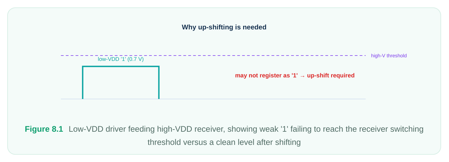
A level shifter resolves both cases. It is a small cell, typically powered by both the source and destination rails (or at least the destination rail plus a reference), whose job is to take a signal referenced to one supply and re-emit it cleanly referenced to the other.
Types of Level Shifters
There is no single "level shifter." The right cell depends on the direction of the crossing and on which supplies are available at the boundary. Typical rail
Type Direction Notes
| Up shifter | Low to high | Both VDDL | Most common; needs the low rail to interpret the |
|---|---|---|---|
| and VDDH | input and the high rail to drive the output | ||
| Down shifter | High to low | Often single- rail (VDDL) | Simpler; sometimes a buffer on the low rail suffices, but a characterized down shifter is safer |
| Dual-rail shifter | Either, robust | Both rails always | Used when the boundary must tolerate a wide voltage spread or either direction |
present
| Enable shifter | Low to high + | Both rails | Translates voltage and clamps the output when the |
|---|---|---|---|
| (combined) | isolation | source domain is off — a fused level-shift-plus- |
isolation cell The up shifter is the workhorse. Internally it uses a cross-coupled pair referenced to the high rail, driven by the low-rail input, so the output is pulled to a full VDDH '1' even though the input only
reached VDDL. It genuinely requires both supplies: the low rail to sense the input swing, the high rail to produce the output. The down shifter is gentler. Because a high-rail '1' already exceeds a low-rail receiver's threshold, the cell mainly conditions the signal and bounds the current. In some libraries a robust buffer on the destination rail is acceptable, but most flows insist on a properly characterized down-shift cell so timing and electrical behavior are signed off rather than assumed. The enable level shifter is worth special attention because it appears constantly in real designs. When the source domain can be powered down, you need both isolation (to clamp the floating output) and level shifting (to translate when the source is on). Rather than placing two separate cells in series, libraries provide a fused cell that does both. It has a data input, an enable/isolation control, and is connected to both rails. This single cell is cleaner, faster, and easier to verify than a discrete shifter feeding a discrete isolation gate.
When a Shifter Is Required Versus Optional
The decision rests on three factors: the direction of the crossing, the magnitude of the voltage difference, and the electrical thresholds defined for your technology. If the source and the sink are at the same voltage — even if they are nominally different power domains — no level shifter is needed. Domain boundaries do not automatically require shifters; voltage boundaries do. This is one of the most common conceptual mistakes, and a good interview answer makes the distinction explicit: a domain crossing is a policy boundary, a voltage crossing is an electrical one. When voltages differ, you compare the difference against a threshold (often expressed as a fraction of the supply, or as an absolute millivolt gap). Below that threshold the levels are close enough that the receiver tolerates the swing and a shifter is optional or omitted. Above it, the shifter becomes mandatory. The threshold is typically tighter for up crossings than for down crossings, reflecting the asymmetry described earlier.
# Conceptual: define when a shifter must be inserted on a crossing.
# A threshold expresses how much voltage difference is tolerable
# before translation is required.
set_level_shifter_strategy \
-name      ls_core_to_io \
-domain    pd_io \
-rule      low_to_high \
-threshold 0.10 \
-location  parent \
-applies_to outputs
The conceptual knobs above recur across every power-intent flow, regardless of the specific command spelling:
- rule — which direction this strategy covers:
low_to_high,high_to_low, orboth.
- threshold — the voltage gap above which a shifter is forced.
- location — which side of the boundary the cell is physically placed and which region's supply feeds it.
- applies_to — whether the strategy governs inputs, outputs, or both of the named domain.
The Placement Decision
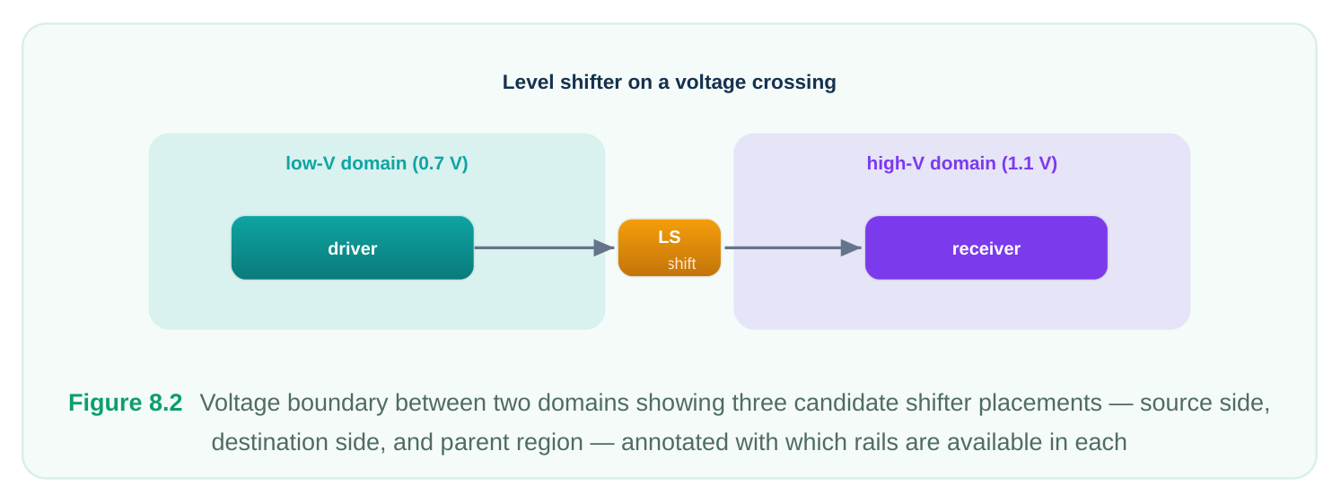
Specifying that a shifter is needed is only half the job; you must also decide where it lives. Placement matters because the cell must have its required supplies available locally, and because the choice affects timing and physical legality. Three considerations drive the call:
- 1. Which side of the boundary. A shifter can sit on the driving side or the receiving side. The
deciding factor is usually supply availability — the cell must be in a region where both of its required rails are routed.
- 2. Whose region it occupies. If the shifter goes in the receiving domain's area, it draws the receiving
supply; if it goes in the driving domain's area, the driving supply. For an up shifter needing both rails, it must be placed where both rails physically exist, which often means a special boundary region or the parent of both domains.
- 3. Interaction with power-down. If the source domain switches off, a shifter placed inside that
source region would lose its input rail and float. In that case the cell belongs on the always-on or destination side, frequently as a combined enable shifter.
Specifying a Strategy Conceptually
A level-shifter strategy is a rule, not a per-net edict. You describe the class of crossings to handle and let the implementation tool insert cells where the rule matches. The strategy names the affected domain, the direction it covers, the threshold, where cells go, and what subset of ports it applies to. You can layer multiple strategies — for instance, one for up crossings on outputs and another for down crossings on inputs — and the tool resolves each boundary against the matching rule.
# Two complementary strategies on the same domain:
# up-shift the outputs, down-shift the inputs.
set_level_shifter_strategy \
-name       ls_up_out \
-domain     pd_dsp \
-rule       low_to_high \
-applies_to outputs \
-location   self
set_level_shifter_strategy \
-name       ls_dn_in \
-domain     pd_dsp \
-rule       high_to_low \
-applies_to inputs \
-location   self
It is good practice to also constrain which library cells a strategy may use, so the inserted shifters match what was characterized for timing and the cell's rail connections are explicit. Leaving cell selection entirely implicit invites the tool to pick a cell whose second rail is not actually present at the chosen location.
Interaction With Isolation, Retention, and DVFS
Level shifters never live in isolation — pun intended. They share the boundary with several other lowpower constructs. With isolation. When a source domain powers down, its outputs float, and isolation cells clamp them to a known value. If that same boundary is also a voltage crossing, you need both functions. The clean solution is the enable level shifter: one cell that translates the voltage when the source is alive and clamps the output when it is off. Ordering matters — the clamp must reference a rail that stays up, and the translation must use the destination rail. A fused cell guarantees this ordering; two discrete cells in the wrong sequence (shifter then isolation, or isolation in the wrong domain) can reintroduce a float or a level error. With retention. Retention preserves a register's state across a power-down. The retained state lives on an always-on rail, but the outputs of a retention register still cross into neighboring domains. Those crossings obey the same shifter rules as any other. The subtlety: retention concerns when the value is valid across a power cycle, while the shifter concerns what voltage that value is presented at. They are orthogonal but co-located, and both must be correct at the same port. With DVFS. Dynamic voltage and frequency scaling makes the boundary time-varying. A domain that runs at 0.9 V in performance mode and 0.6 V in low-power mode changes its relationship to its neighbor mode by mode. A crossing that is high-to-low in one operating mode can become low-to-high in another — the direction flips. This is why robust designs at DVFS boundaries use dual-rail shifters that work in either direction, or specify the strategy with -rule both . Verifying a DVFS boundary means checking every legal voltage combination across modes, not just the nominal one.
# A DVFS-aware boundary: direction can flip between modes,
# so cover both directions with a single bidirectional rule.
set_level_shifter_strategy \
-name       ls_dvfs_bndry \
-domain     pd_scalable \
-rule       both \
-threshold  0.08 \
-location   parent \
-applies_to both
Common Errors: Detection and Fix
| Error | How it shows up | Fix |
|---|---|---|
| Missing shifter | Static low-power check flags an unshifted | Add a strategy covering that domain/ |
| on a voltage | crossing; silicon shows logic failures or | direction; confirm the boundary now reports |
| crossing | excess current | a cell |
| Wrong direction | Up shifter on a high-to-low path (or vice versa); check reports direction mismatch | Correct the -rule ; re-verify both modes if DVFS is involved |
| Shifter without | Cell inserted but one supply pin | Move placement ( -location ) to a region |
| its second rail | unconnected or unavailable at that location; electrical/connectivity check fails | where both rails exist, or pick a single-rail cell appropriate to the direction |
| Float at a power- | Shifter present but no isolation; output | Replace with an enable level shifter or add |
| down crossing | floats when source is off | correctly ordered isolation |
| DVFS direction | Boundary passes nominal mode, fails an | Switch to -rule both / dual-rail cell; |
| not covered | alternate mode | verify the full mode matrix |
The detection mechanism for all of these is static low-power verification — a structural check that walks every domain boundary, computes the source and sink voltages for each operating mode, and reports any crossing that lacks a correctly directed, correctly powered shifter. This catches problems long before simulation and is far more exhaustive than dynamic testing, because it considers every boundary in every mode rather than only the paths a testbench happens to exercise. A disciplined flow runs this check after every change to the power intent, treats unshifted-crossing reports as hard errors, and only signs off the boundary list when it is empty across all modes.
Worked Example
Picture a system-on-chip with three regions. A sensor front-end runs at a fixed 0.6 V to save power. A processing core uses DVFS, alternating between 1.0 V (performance) and 0.7 V (efficiency). An I/O ring runs at a steady 1.2 V.
Walk each crossing:
- Sensor (0.6 V) into core. In performance mode the core is at 1.0 V, so this is 0.6 to 1.0 — a clear up crossing well past threshold. Up shifter required. In efficiency mode the core drops to 0.7 V; still
0.6 to 0.7, a small up crossing. Depending on the threshold this may still need a shifter, so the safe choice is an up shifter sized for the worst case. The sensor never powers down here, so no isolation is needed on this path.
- Core into I/O (1.2 V). Performance mode: 1.0 to 1.2, an up crossing. Efficiency mode: 0.7 to 1.2, a larger up crossing. Direction is consistent across modes, so a single up shifter covers both. Up shifter required. If the core can power down while I/O stays alive, this becomes an enable level shifter.
- I/O (1.2 V) into core. Performance: 1.2 to 1.0, down crossing. Efficiency: 1.2 to 0.7, down crossing. Down direction in both modes — a down shifter (or a characterized buffer if the library permits) handles it.
- Core internal feedback to itself. Same domain, same supply in any given mode — no shifter. The crossing is not a voltage crossing. The trap in this example is imagining a core-to-sensor path. If such a path existed, performance mode (1.0 to 0.6, down) and a hypothetical scaled mode could keep it down — but had the sensor itself been scalable, the direction could flip and demand a
-rule bothstrategy. The lesson: always enumerate the supply pair per mode before choosing a cell.
Do I Need a Shifter? Decision Table
Assume a threshold below which close voltages are tolerated. "Maybe" means it depends on whether the gap exceeds your technology's threshold.
| Source voltage | Sink voltage | Crossing | Shifter? |
|---|---|---|---|
| 0.6 V | 0.6 V | Equal | No |
| 0.6 V | 0.7 V | Up, small | Maybe (threshold-dependent) |
| 0.6 V | 1.0 V | Up, large | Yes (up) |
| 0.7 V | 1.2 V | Up, large | Yes (up) |
| 1.2 V | 1.0 V | Down, small | Maybe / down |
| 1.2 V | 0.6 V | Down, large | Yes (down) |
| Scaled (varies) | Fixed | Flips by mode | Yes (both / dual-rail) |
| Any | Same domain, same rail | None | No |
Interview Q&A
voltage. Does it need a level shifter? No. Level shifters address voltage differences, not domain membership. Two distinct domains at identical voltage have a policy boundary, not an electrical one. You might still need isolation if one domain can power down, but translation is unnecessary. Conflating domain crossings with voltage crossings is the classic novice error — always check the actual supply levels per mode.
only reaches the low rail, which may sit below the high-rail receiver's switching threshold — so the receiver cannot be relied on to register it, and the cell must actively pull the output to the full high rail using a cross-coupled stage referenced to that rail. It genuinely needs both supplies. Going high-tolow, the incoming full-rail '1' already exceeds the low receiver's threshold, so the function works; the only concern is bounding the current and reliability stress, which a simpler cell handles. Asymmetric difficulty leads to asymmetric thresholds.
Because the voltage relationship changes with operating mode. If one side scales from 1.0 V down to 0.5 V while the neighbor stays at 0.8 V, the crossing is high-to-low in performance mode but low-tohigh in efficiency mode. A unidirectional cell would be correct in one mode and wrong in the other. You either specify -rule both so a bidirectional/dual-rail cell is inserted, or you verify that no legal mode combination actually flips the direction. The verification must cover the full mode matrix, not just nominal.
the same cell. What likely happened, and how do you fix it? The shifter almost certainly needs two rails and was placed where only one is physically available — its second supply pin is unconnected. An up shifter dropped inside the low domain's region, for example, has the low rail but not the high one. The fix is to change placement so the cell sits where both rails are routed — often the parent region spanning both domains or the always-on/destination side — by adjusting the strategy's location. Alternatively, if the direction truly only needs one rail, select a single-rail cell appropriate to that direction. Either way, re-run both the low-power structural check and connectivity to confirm.
Key Takeaways
- A level shifter exists to translate a signal's voltage reference at a boundary where source and sink supplies differ; it is driven by the electrical gap, not by domain membership.
- Up (low-to-high) crossings risk functional failure and need both rails; down (high-to-low) crossings risk excess current and are electrically simpler. Thresholds are asymmetric for this reason.
- Same-voltage crossings — even between different domains — need no shifter; do not confuse a policy boundary with a voltage boundary.
- A shifter strategy is a rule specifying direction, threshold, location, and which ports it applies to; constrain the allowed cells so the inserted shifter actually has the rails it needs.
- Combine shifting with isolation using an enable level shifter wherever the source can power down, so the output is both translated and clamped by one ordered cell.
- DVFS can flip crossing direction by mode; cover such boundaries with
-rule bothor dual-rail cells and verify the entire mode matrix. - Static low-power verification is your safety net: it walks every boundary in every mode and flags missing, mis-directed, or mis-powered shifters far more thoroughly than simulation.
Comments
Leave a Reply