 ChipBuddy
← Home
ChipBuddy
← Home
Domain Boundaries, Feedthroughs & Related Supplies
Chapter 11 — Domain Boundaries, Feedthroughs & Related
Supplies
If there is one place in a low-power design where correctness lives or dies, it is the power-domain boundary. Everything you learned about isolation cells, level shifters, retention, and power switches finally comes together here, at the literal edge where one supply region meets another. A boundary is not a passive line on a floorplan; it is a decision point. For every signal that crosses it, the power-intent tooling must answer two questions: does this crossing need its level translated? and does this crossing need to be held safe while one side is off? Get the answer right and the chip works across all power states. Get it wrong and you ship a part that fails only when a particular domain powers down in a particular order — the worst kind of bug, because it hides until silicon. This chapter explains how the tool reasons about a boundary, what happens when domains nest, and the often-misunderstood machinery of related supplies and feedthrough nets. These are the topics that separate an engineer who can run a flow from one who understands it.
The Boundary as the Central Place Where Correctness Is Decided
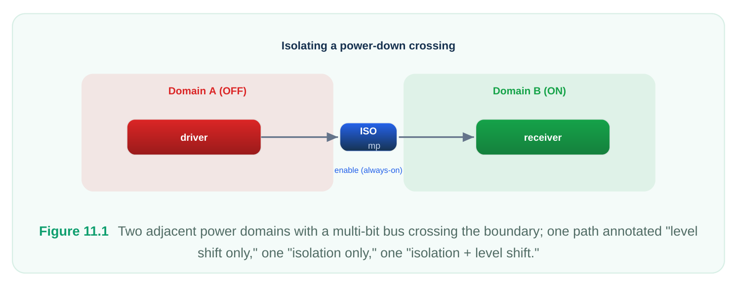
A power domain is a collection of logic that shares the same primary supply and the same powercontrol behavior. The boundary of a domain is the set of ports — both the domain's own interface and
the pins of instances facing outward — through which signals enter and leave. Because the supply can differ on each side, and because either side can be independently switched, every crossing carries risk. There are exactly two physical hazards at a crossing:
- 1. Voltage mismatch. If the driver and receiver operate at different voltages, the receiving gate may
see a logic level it cannot interpret cleanly, drawing crowbar current or producing an indeterminate output. The fix is a level shifter.
- 2. Floating or corrupted source. If the driving domain is powered down while the receiving domain
is still on, the crossing net floats to an unknown value, which can propagate X, cause contention, or burn static current. The fix is an isolation cell that clamps the net to a known value. A single crossing may need neither, either, or both protections, and when it needs both, the order matters (typically isolate on the always-on side of the shift, but the exact requirement depends on the cell library and the states involved). The boundary is where the tool decides the combination.
How the Tool Reasons About a Boundary
The reasoning is fundamentally a comparison of source supply versus sink supply for each crossing net. The source supply is the supply of the driver; the sink supply is the supply of the receiver. From this pair, the tool derives requirements:
| Source vs. Sink | Can sink be on while source is off? | Tool conclusion |
|---|---|---|
| Same supply, same voltage | No (single rail) | No special cell |
| Same voltage, independently switchable | Yes | Isolation needed |
| Different voltage, both always-on | No | Level shifter needed |
| Different voltage, independently switchable | Yes | Isolation + level shifter |
Direction matters for shifters. A low-to-high crossing and a high-to-low crossing are not the same cell; the tool selects the shifter type and direction from the source/sink voltage relationship. This is why the
tool must know not just that two supplies differ but which is higher in every relevant state. The same boundary can require an up-shifter in one operating corner and behave benignly in another if the voltages are scheduled to be equal in that mode. The decisive inputs to this reasoning are therefore: the supply attached to the driver, the supply attached to the receiver, the set of power states in which each can be on or off, and the relative voltages in each state. If any of these is unknown or ambiguous, the tool either inserts conservatively (wasting area and power) or fails to insert (creating a silicon bug). Everything that follows in this chapter is, at bottom, about making those four inputs unambiguous.
Lower-Domain and Nested-Domain Boundaries
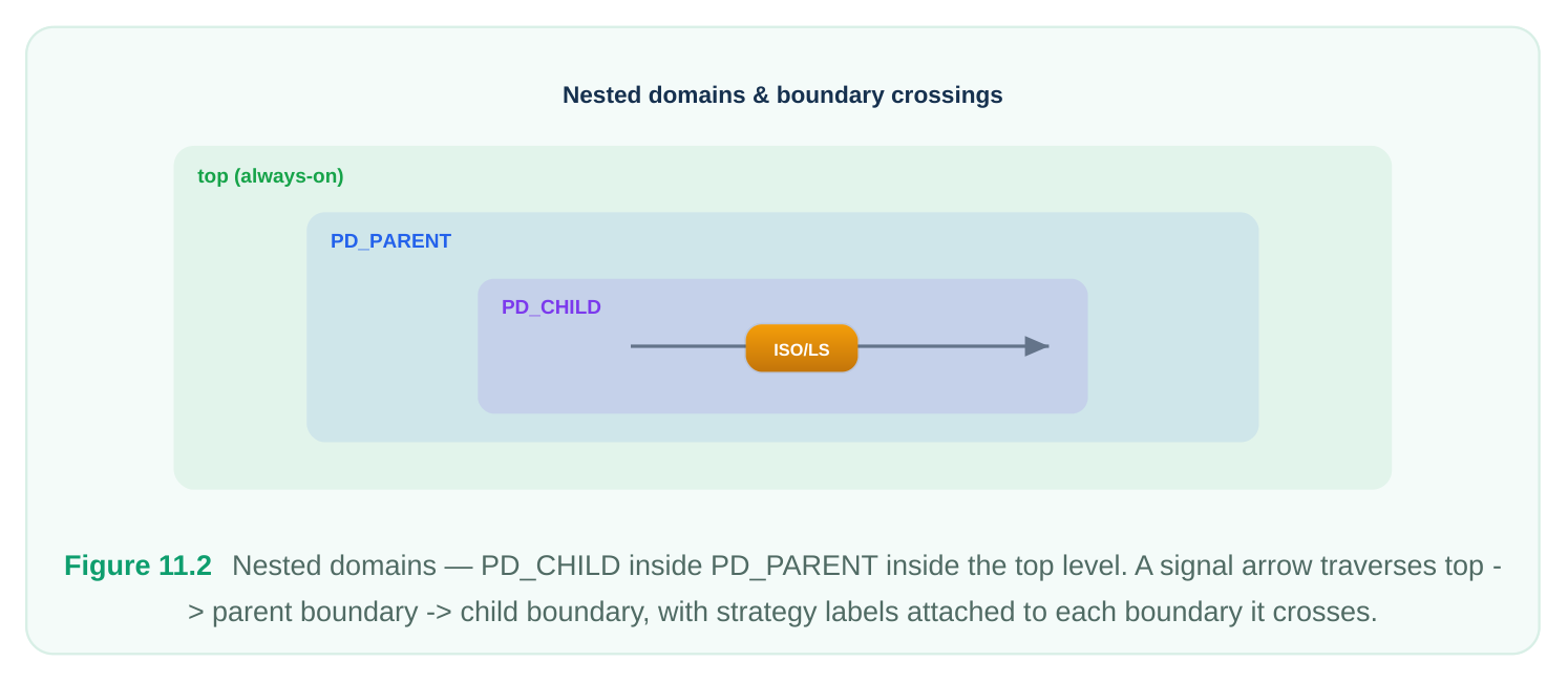
Real designs are hierarchical, and power domains nest. A parent domain contains a child (or lower) domain — for example, an always-on controller wrapping a switchable accelerator core. Nesting creates a second, inner boundary, and signals frequently cross both the parent's outer boundary and the child's inner boundary. The key mental model: a strategy defined on a domain governs that domain's own boundary. A parentdomain isolation strategy protects signals crossing the parent boundary; a child-domain strategy protects signals crossing the child boundary. They are independent specifications that happen to apply to the same physical wire when a signal passes from the outside world, through the parent, into the child. Consider a signal sourced outside the parent, terminating inside the child. It crosses the parent boundary (governed by parent strategies) and then the child boundary (governed by child strategies). If only the parent has an isolation strategy and the child is the thing that actually powers down, the protection is in the wrong place and the child's outputs go unguarded. The corollary is the most common nested-domain mistake: missing the lower-domain strategy. Designers define the obvious top-level rule and forget that the inner switchable block needs its own.
# Parent domain rule: isolate everything leaving the parent
set_isolation parent_iso \
-domain PD_PARENT \
-isolation_power_net VDD_AON \
-isolation_ground_net VSS \
-clamp_value 0 \
-applies_to outputs
# Child (lower) domain rule: the switchable core needs its OWN strategy
set_isolation child_iso \
-domain PD_CHILD \
-isolation_power_net VDD_AON \
-isolation_ground_net VSS \
-clamp_value 0 \
-applies_to outputs
When strategies on parent and child both touch a signal, the tool resolves which boundary each applies to by the location of the port relative to each domain. An output of the child is, from the parent's perspective, an internal driver feeding the parent's logic; from the child's perspective it is a boundary output. Understanding whose boundary you are standing on when you read a strategy is the single most useful skill in debugging nested-domain insertion.
Feedthrough Nets
A feedthrough is a net that physically routes through a region without connecting to any of that region's logic. The classic case: a wire enters a block's left edge, runs across, and exits the right edge, never touching a gate inside. The block is just real estate it happens to traverse. Feedthroughs are dangerous precisely because they look like boundary signals but are not. The tool, seeing a net enter and leave a domain, may assume the domain is the source or sink and reason about isolation or shifting based on that domain's supply — even though the domain neither drives nor receives the net. The result is a cell inserted against the wrong reference, or a spurious level shifter where the true source and true sink are at the same voltage. The fix is to tell the tool the feedthrough's true electrical reference — its related supply — so the tool understands the net is merely passing through and reasons about it against the correct supplies, not the supply of the region it crosses.
# This net passes straight through PD_BRIDGE without connecting to its logic.
# Tell the tool its true reference supply so it is NOT treated as a
# PD_BRIDGE boundary signal.
set_related_supply_net \
-object_list [get_ports thru_data_in] \
-power VDD_SRC \
-ground VSS
set_related_supply_net \
-object_list [get_ports thru_data_out] \
-power VDD_SRC \
-ground VSS
The Related-Supply Concept
The related supply of a port is the supply against which that port's logic level is referenced. It answers, "if this port sits at logic 1, what voltage is that?" Boundary analysis is impossible without it, because the entire source-vs-sink comparison depends on knowing each port's reference. For most ports, the related supply is inferred automatically from the domain the port belongs to. Problems arise at the seams: hard macros whose interfaces are at a different voltage than the surrounding domain, feedthroughs, and ports whose driver and receiver legitimately sit on different rails. In these cases you must declare the reference explicitly. A correctly declared related supply turns an ambiguous crossing into a definite one, and the tool's conclusion — shifter, isolation, both, or nothing — follows cleanly.
| Concept | What it tells the tool | Typical command style |
|---|---|---|
| Related supply | Which supply a port's level is referenced to | set_related_supply_net |
| Driver supply | The supply of whatever drives this port | port attribute: driver supply |
| Receiver supply | The supply of whatever this port drives | port attribute: receiver supply |
| Feedthrough handling | This net only passes through; use its true reference | related supply on both ends |
Port and Boundary Attributes
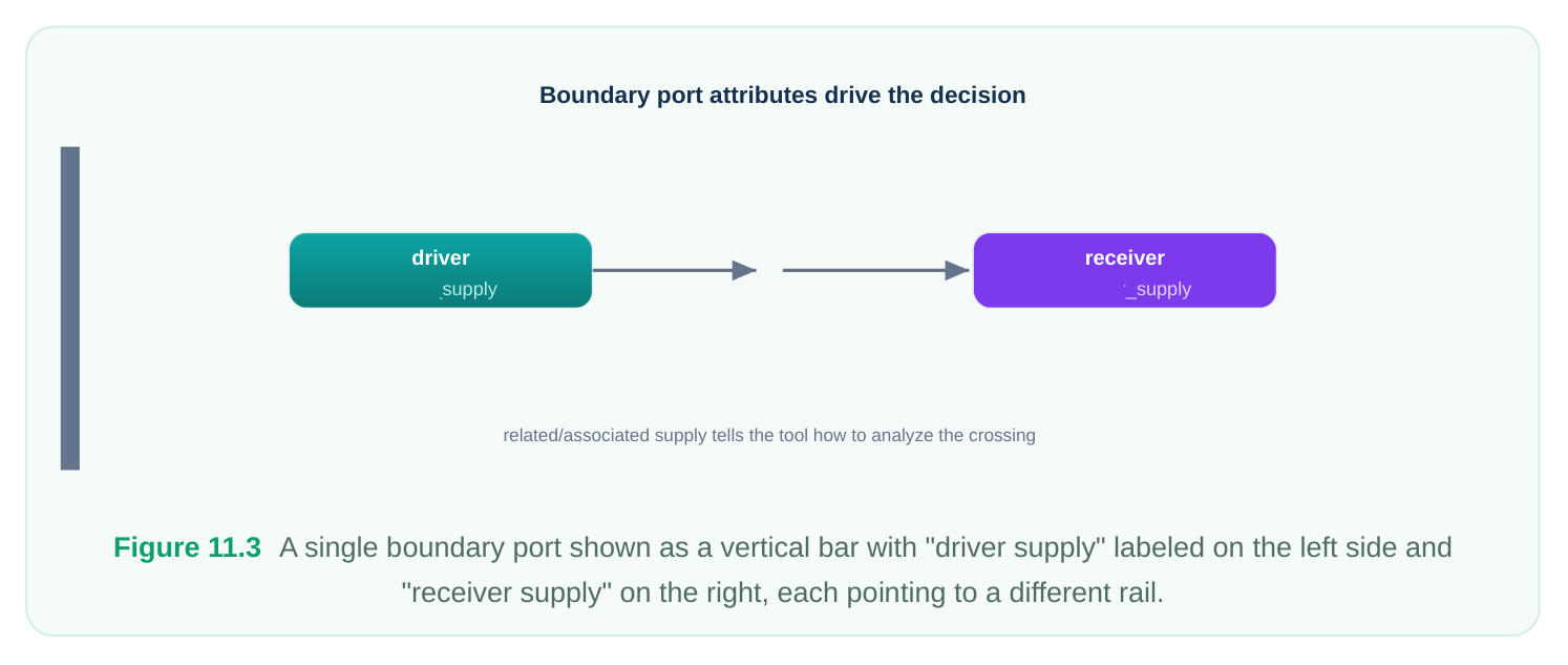
A boundary port has two electrical sides, and the tool may need both described. The driver supply characterizes what is on the upstream side of the port; the receiver supply characterizes the downstream side. At a block boundary you frequently know only one side from inside the block — the other side lives in the parent — so you annotate the missing side as an attribute so block-level analysis matches what will happen at the top.
# Describe both sides of a boundary port so block-level boundary
# analysis matches the eventual top-level context.
set_port_attributes \
-ports [get_ports cfg_bus*] \
-driver_supply VDD_AON \
-receiver_supply VDD_CORE
# For an output whose external load lives at a different voltage,
# declare the receiver side explicitly.
set_port_attributes \
-ports [get_ports status_out] \
-receiver_supply VDD_IO
These attributes are how a block author communicates intent to whoever integrates the block. Without them, the integrator's top-level run is the first time the true two-sided picture exists — and any shifter or isolation the block assumed may turn out wrong. Treat boundary attributes as part of the block's contract, on par with its timing constraints.
Pitfalls: Detection and Fix
Feedthrough taking the wrong related supply. Symptom: a level shifter or isolation cell appears on a net that should be a clean pass-through, or a needed cell is missing because the tool thought the feedthrough domain's supply matched. Detection: in the inserted-strategy report, look for cells whose reference supply is the traversed region rather than the true endpoints; cross-check against the connectivity to confirm the net never touches the region's logic. Fix: declare the related supply on both feedthrough endpoints to the true source/sink supply. Ambiguous boundary. Symptom: the tool reports it cannot determine a port's supply, or it inserts conservatively (a shifter "just in case"). Detection: scan the analysis log for unresolved-supply or undriven-port messages at boundaries; these are warnings people learn to ignore at their peril. Fix: declare the related supply or the driver/receiver attributes so the comparison is well-defined. Missing lower-domain strategy. Symptom: a switchable child block's outputs are unprotected when the child powers down, surviving block-level checks (where the child looks always-on relative to its
own contents) and failing only at full-chip multi-state verification. Detection: enumerate every switchable domain and confirm each has its own isolation strategy covering its boundary outputs; never assume a parent rule reaches inward. Fix: add the explicit child-domain strategy as shown earlier. A disciplined reviewer runs the same three checks on every boundary: Is each crossing port's reference unambiguous? Does every switchable domain own its boundary strategy? Is every feedthrough referenced to its true endpoints, not the region it crosses?
Worked Conceptual Example
A bridge block, PD_BRIDGE , sits at 0.7 V . Through it runs a configuration bus driven by an always-on controller at 0.9 V and consumed by a core at 0.6 V . The bus does not touch the bridge's logic — it is a pure feedthrough. The bridge also has its own switchable inner block, PD_BRIDGE_CORE .
# 1. The config bus is a feedthrough; reference it to its TRUE endpoints,
#    not to PD_BRIDGE's 0.7 V supply.
set_related_supply_net -object_list [get_ports cfg_thru_in]  -power VDD_CTRL -ground
VSS
set_related_supply_net -object_list [get_ports cfg_thru_out] -power VDD_CORE -ground
VSS
# 2. Declare both sides of the boundary so the true crossing
#    (0.9 V controller -> 0.6 V core) drives shifter selection.
set_port_attributes -ports [get_ports cfg_thru_in]  -driver_supply  VDD_CTRL
set_port_attributes -ports [get_ports cfg_thru_out] -receiver_supply VDD_CORE
# 3. The switchable inner block owns its boundary isolation strategy.
set_isolation bridge_core_iso \
-domain PD_BRIDGE_CORE \
-isolation_power_net VDD_AON \
-isolation_ground_net VSS \
-clamp_value 0 \
-applies_to outputs
With this intent, the tool reasons correctly: the feedthrough is analyzed as a 0.9 V -> 0.6 V crossing handled at its real endpoints (no spurious cell against the bridge's 0.7 V ), and the inner switchable block carries its own isolation so its outputs stay defined when it powers down. Remove any one of these three declarations and you reintroduce one of the three classic pitfalls.
Interview Q&A
decided"? Because every physical low-power hazard — voltage mismatch and floating/corrupted nets — manifests at a crossing, and the required mitigations (level shifters, isolation, or both) are determined per crossing by comparing source and sink supplies across all power states. Logic in the
interior of a single-supply domain carries none of these risks; the boundary is where independent supplies meet and where the tool makes its insert/don't-insert decisions.
neither? It compares the driver's supply to the receiver's supply. If voltages differ, a shifter is required, with direction set by which side is higher in each relevant state. If the two domains can be independently powered such that the source can be off while the sink is on, isolation is required to clamp the net. Both conditions can hold simultaneously, requiring both cells. If supplies are identical and never independently switched relative to each other, neither is needed.
that routes through a region without connecting to that region's logic. The tool, seeing the net enter and leave a domain, may wrongly treat the traversed domain's supply as the source or sink, inserting cells against the wrong reference or missing genuinely required ones. Declaring the related supply on both ends tells the tool the net's true electrical reference, so it analyzes the real source-to-sink crossing rather than the irrelevant region it passes through.
an isolation strategy. What happened and how do you fix it? A strategy applies only to its own domain's boundary. The parent's strategy protects the parent boundary, not the inner child boundary, so when the child powers down its outputs float. The fix is an explicit isolation strategy on the child domain covering its boundary outputs. This is the classic missing-lower-domain-strategy bug; it survives block-level checks and surfaces only under full-chip multi-state verification, which is why every switchable domain must be confirmed to own its boundary strategy.
Key Takeaways
- The domain boundary is the decision point for power correctness: every crossing needs the right combination of isolation and/or level shifting, determined per net.
- The tool reasons by comparing source supply to sink supply across all power states; voltage difference drives shifter type and direction, independent switchability drives isolation.
- Strategies apply to their own domain's boundary. In nested designs, the parent rule does not reach into the child — every switchable domain must own its boundary strategy.
- A feedthrough must be referenced to its true endpoints via its related supply, or the tool will reason against the region it merely passes through.
- The related supply answers "what voltage is this port's logic 1?"; declare it (and driver/receiver attributes) wherever inference is ambiguous, especially at macro seams and block interfaces.
- Boundary attributes are part of a block's integration contract; describe both sides of a port so block- level analysis matches the eventual top-level context.
- Review every boundary with three questions: unambiguous references, child-owned strategies, and correctly referenced feedthroughs.
Comments
Leave a Reply