 ChipBuddy
← Home
ChipBuddy
← Home
Isolation Strategies
When a power domain shuts down, it does not gracefully announce its departure to the rest of the chip. Its supply collapses, its internal nodes drift, and every wire that once carried a clean logic value now carries something indeterminate. The neighbouring domains that are still powered up keep listening on those wires — and what they hear is noise. Isolation is the discipline of making sure that what leaves a sleeping domain is always a defined, harmless value rather than an unknown one. It is one of the few low-power techniques where getting it slightly wrong does not merely cost a little power or a little timing margin; it can produce functional failure, crowbar current, or silent data corruption that survives all the way to silicon. For that reason, interviewers probe isolation hard, and they expect you to reason about it precisely.
Why a Powered-Down Domain Is Dangerous
Consider two domains: a switchable domain A that can be turned off to save leakage, and an alwayson domain B that receives several signals from A . While A is powered, its output drivers hold proper logic levels and B behaves normally. The instant A 's supply is removed, the transistors in A 's output stage lose their drive strength. The output nets are no longer driven to 0 or 1 ; they float toward an intermediate, slowly-decaying voltage that simulators represent as X .
That X is not a cosmetic annoyance. It propagates into B and can do real damage:
- Logical corruption. An
Xthat reaches an enable, a clock-gate condition, or a state-machine input inBcan flipBinto an illegal state. The corruption persists afterAwakes up because the damage was already done. - Crowbar (short-circuit) current. If a floating net settles near the switching threshold of a receiving gate in
B, both the pull-up and pull-down networks of that gate can conduct simultaneously. A single such gate leaks; thousands of them across a wide interface can draw enough current to defeat the entire purpose of poweringAdown. - Memory and control hazards. A floating write-enable or reset reaching a register file or controller in
Bcan trigger spurious writes or resets.
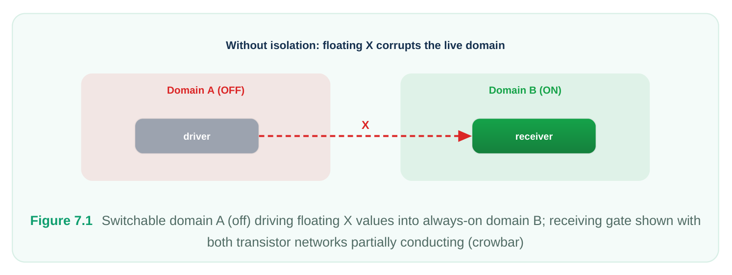
The fix is conceptually simple: place a small cell on the crossing that, when A is off, ignores A 's output and instead drives a known constant. This is an isolation cell (sometimes called a clamp). When A is on, the cell is transparent and passes the real value through.
How an Isolation Cell Behaves
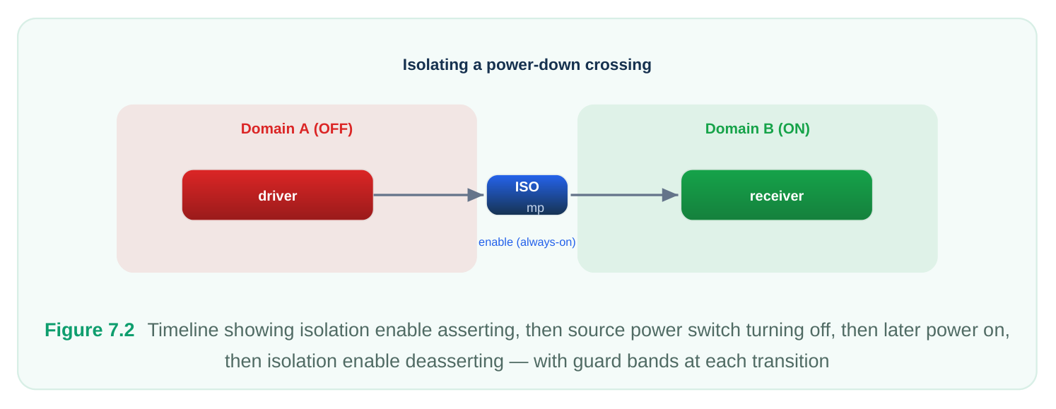
An isolation cell has three logical pieces: a data input from the source domain, a data output toward the sink domain, and an isolation control (often called the isolation enable). When control is in its inactive state, the cell passes data through unchanged. When control is asserted — meaning "the source is going down, clamp now" — the output is forced to a defined value regardless of the input. Three clamp behaviours are common:
| Clamp type | Output while isolated | Typical use |
|---|---|---|
| Clamp-to-0 | Logic 0 | Active-high enables, requests, valids — default safe value |
| Clamp-to-1 | Logic 1 | Active-low resets/enables, handshake acks that must stay |
deasserted
| Latch / hold-last- | Frozen pre-shutdown | Buses where the receiver must keep the last stable word (e.g. |
|---|---|---|
| value | value | a captured address) |
A clamp-to-0 cell is essentially an AND of the data with the inverted control; a clamp-to-1 cell is an OR of the data with the control. A hold cell contains a latch that captures the value just before isolation engages and presents it for the duration of the power-down. Hold cells are larger and need careful control timing, so they are used sparingly. The single most important property of the control signal is that it must come from a domain that stays on the whole time the source is off. If the isolation enable itself were generated inside the domain being powered down, it would go X exactly when you need it most, and the clamp would be uncontrolled. The control therefore originates in an always-on domain or in the power-management logic, and it must be asserted before the source supply is removed and deasserted after the supply is restored and stable.
Where Isolation Belongs
Isolation is needed only on signals that leave a switchable domain and enter a domain that remains on while the source is off. Walking through the cases makes the rule concrete:
- Off-domain output to on-domain input — needs isolation. This is the dangerous crossing.
- On-domain output to off-domain input — does not need isolation. The receiver is off and does not care what arrives; the source is well-behaved.
- Two domains that are always off or always on together — no isolation needed for that pair, because there is never a moment when one is dead and the other is listening.
- A signal that stays entirely within one domain — never needs isolation. The second decision is location: physically, should the isolation cell sit in the source domain or in the sink domain? The cell must be powered by a supply that is alive during the power-down, so it cannot draw its supply from the domain being shut off. Common choices are to place the cell in the always-on sink domain, or in an always-on region, or to give the source domain a small always-on supply rail dedicated to its isolation cells. Placing isolation on the source side keeps long isolated routes from floating, but requires that always-on rail to be routed into the switchable region; placing it on the sink side keeps the switchable region simple but lets the un-isolated wire run through floating territory. The right answer depends on floorplan and route length, and you should be ready to argue both sides in an interview.
Specifying an Isolation Strategy
In the open power-intent standard, isolation is described declaratively rather than by hand-instantiating cells. You tell the implementation tool four things: which signals to isolate, what value to clamp them to, which signal controls the clamp, and where (source or sink side) the cells should sit. The tool then inserts and connects the cells. Conceptually it looks like this:
# Define the strategy: isolate the outputs of the switchable domain
set_isolation iso_A_outputs \
-domain          PD_A \
-isolation_power_net  VDD_AON \
-isolation_ground_net VSS \
-clamp_value     0 \
-applies_to      outputs
# Tie the strategy to its always-on control and pick a location
set_isolation_control iso_A_outputs \
-domain    PD_A \
-isolation_signal  iso_en_aon \
-isolation_sense   high \
-location  parent
The -isolation_power_net / -isolation_ground_net make explicit that the cells run off the alwayson rail. -clamp_value 0 selects clamp-to-0 behaviour. -isolation_signal names the always-on control and -isolation_sense high says the clamp engages when that signal is 1 . -location parent places the cells on the sink side (the enclosing always-on parent), as opposed to self for the source side. For interfaces with mixed requirements you typically write several strategies, each targeting a port subset. A handshake ack that must read as "not acknowledged" while the source sleeps is clamped to its inactive value, while a captured configuration word may use a hold cell:
# Clamp the request line to its inactive (0) value
set_isolation iso_req -domain PD_A -applies_to outputs \
-elements {u_core/req_o} -clamp_value 0
# Hold the last captured config word for the receiver
set_isolation iso_cfg -domain PD_A -applies_to outputs \
-elements {u_core/cfg_word_o[*]} -clamp_value latch \
-isolation_signal iso_en_aon -isolation_sense high
Granularity and Exceptions
Real interfaces are rarely uniform, so isolation strategies support exceptions. You may apply a blanket clamp-to-0 to a domain's outputs and then carve out a handful of ports that need different treatment, or that need no isolation at all. A common reason to exclude a port is that it already terminates in another off domain, or that it is a true always-on feed-through that never floats.
Isolation also frequently combines with level shifting when the source and sink domains run at different voltages (covered in the level-shifting chapter). The order matters: the signal must be both clamped to a safe value and shifted to the receiver's voltage. The two functions can be merged into a single combined cell — an isolation-plus-level-shift cell — which is more area-efficient than two separate cells in series and avoids an extra floating node between them. When you specify both strategies on the same crossing, you must ensure the tool understands they coexist on the same path rather than conflicting.
| Situation | Isolation? | Level shift? | Cell choice |
|---|---|---|---|
| Off → on, same voltage | Yes | No | Isolation cell |
| Off → on, different voltage | Yes | Yes | Combined iso + level-shift cell |
| On → off, different voltage | No | Yes | Level-shift cell only |
| Same-state pair, different voltage | No | Yes | Level-shift cell only |
DFT and Scan Interaction
Isolation and design-for-test pull in opposite directions and must be reconciled deliberately. During scan test you want every flop reachable and every path observable; isolation, by design, blocks paths and forces constants. If the test methodology powers all domains up for scan, isolation enables should be held inactive (transparent) during shift and capture so the scan chain passes real data. If a scan chain physically threads through a switchable domain that is intended to be tested while another domain is off, the isolation on that chain's crossing must be controllable from the test controller, not stuck in clamp. The classic mistake is letting an isolation enable that is tied to the power-management sequencer remain asserted during scan, which freezes part of the scan chain at a constant and produces unexplained stuck-at coverage loss or chain-integrity failures. The remedy is to make the isolation control test-aware: bypass or override it under a test-mode signal so the cell is transparent during scan, while preserving its real behaviour in functional mode.
# Functional isolation enable, made transparent during scan
assign iso_en_aon_eff = scan_mode ? 1'b0 : iso_en_pmu;
# 0 = transparent (clamp off); scan sees real data through the cell
You also have to confirm that the always-on isolation control net is itself on a tested, controllable path — a control signal that cannot be exercised in test is a coverage hole and a reliability risk.
Common Violations and How to Fix Them
Isolation bugs cluster into a few recurring patterns. A static low-power rule checker (the equivalent of a power-aware lint) is the primary tool for catching them before they reach simulation or silicon.
Missing isolation on a power-down crossing. A signal leaves an off-able domain, enters an on domain, and has no clamp. The checker flags an unisolated power-state crossing. Fix by adding the crossing to an isolation strategy. This is the highest-severity violation because it directly causes X propagation and crowbar current. Wrong clamp value. The crossing is isolated, but to the wrong constant — for instance an active-high req clamped to 1 , so the receiver sees a permanent request while the source sleeps. The logic is "isolated" yet functionally broken. Detect this by reviewing each clamp value against the receiver's expected inactive state, and through power-aware functional simulation that exercises the shutdown sequence. Fix by correcting -clamp_value per port. Isolation controlled by a gated or switchable signal. The isolation enable is sourced from logic that can itself power down or be clock-gated off, so the clamp loses control exactly during shutdown. The checker flags a control signal that is not provably always-on. Fix by re-sourcing the enable from a genuine always-on domain and confirming its supply in the power intent. Isolation enable timing wrong relative to the power switch. The clamp is correct but asserts too late (after the supply has already started collapsing) or deasserts too early (before the supply is stable). Brief X glitches escape. Detect through the power-up/down sequence checks and dynamic simulation; fix by tightening the controller sequencing and guard bands. Redundant isolation. A clamp placed on a crossing that never floats (e.g. on → off, or a same-state pair) wastes area and a delay stage and may itself introduce a timing path. Detect via the same crossing analysis that finds missing isolation — it reports "isolation present but not required." Fix by
removing the strategy or excluding those ports.
A Worked Conceptual Example
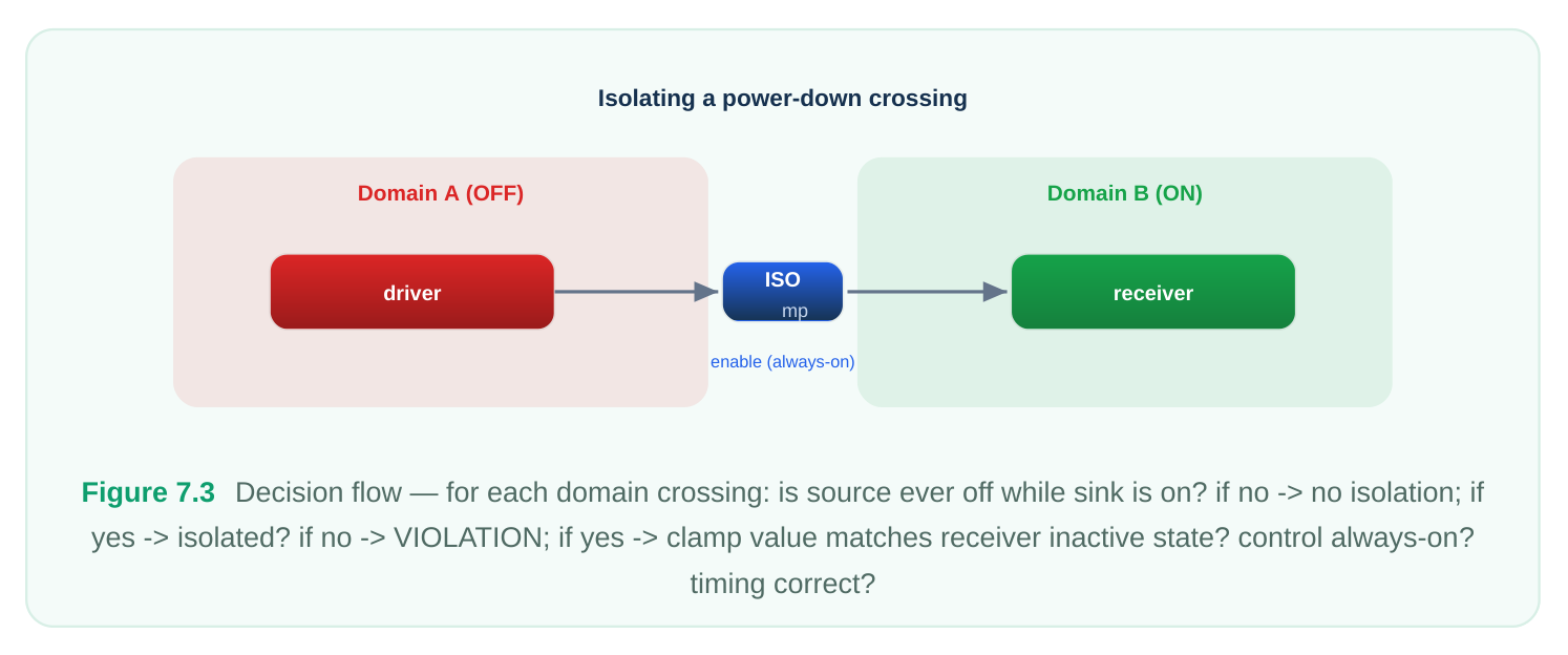
Picture a switchable accelerator domain PD_ACC that feeds an always-on bus-interface domain PD_AON . The accelerator exports four signals: a valid (active-high), an irq (active-high, levelsensitive), a ready_in it drives back as part of a handshake ( ack , active-low), and a 32-bit result bus that PD_AON latches into a result register.
Reason port by port:
valid— active-high; if it floated high,PD_AONwould think data is arriving. Clamp to 0.irq— active-high level interrupt; a floating high would raise a spurious interrupt to the always-on controller. Clamp to 0.ack— active-low; its inactive (deasserted) value is1. Clamp to 1.result[31:0]—PD_AONmust retain the last computed word for read-back after shutdown. Hold last value (latch clamp). The isolation enableiso_enis generated by the always-on power sequencer. It asserts one or more cycles before the accelerator's power switch opens and deasserts only after the accelerator's supply is confirmed good on wake-up. All isolation cells are powered fromVDD_AONand placed on the sink (parent) side so the long buses do not run un-isolated through the switchable region. During scan,iso_enis forced to its transparent state byscan_modeso all four paths shift real data. The matching clamp-value table: Signal Active level Inactive value Clamp strategyvalidHigh 0 Clamp-to-0irqHigh 0 Clamp-to-0ackLow 1 Clamp-to-1result[31:0]n/a (data) last word Hold / latch This single example exercises every concept in the chapter: the source/sink crossing rule, clamp-value selection driven by each receiver's inactive state, the always-on control, location choice, the hold-cell special case, and the scan override.
Interview Q&A
will eventually be reset? Because the damage happens before any reset. A floating output drifts to an intermediate voltage that can settle near a receiving gate's switching threshold, turning that gate into a static short between supply and ground — crowbar current that burns power continuously while the domain is off, defeating the shutdown. The floating X can also propagate into always-on control or memory logic and corrupt state or trigger spurious writes that a later reset cannot undo cleanly. Isolation prevents both by forcing a defined value at the crossing.
receiver needs during the shutdown. Clamp to whatever value is the receiver's inactive/safe state: active-high control signals clamp to 0, active-low ones clamp to 1, so that nothing downstream is spuriously triggered. Use hold-last-value only when the receiver genuinely must keep operating on the pre-shutdown data — for example a captured address or a status word read after the source sleeps.
Hold cells are larger and need careful capture timing, so prefer a constant clamp unless retention of the value is a real functional requirement.
must come from a domain that stays powered for the entire interval the source domain is off — an always-on domain or the power-management controller. If the enable were generated inside the domain being shut down, it would itself go unknown at exactly the moment the clamp must hold, leaving the isolation uncontrolled. A frequent bug is sourcing the enable from logic that is clock-gated or itself switchable; static low-power checks flag any isolation control that is not provably always-on.
forces constants and blocks paths, which is the opposite of what scan needs. If an isolation enable tied to the power sequencer stays asserted during scan, it freezes part of the chain at a fixed value, causing chain-integrity failures or unexplained coverage loss. The fix is to make the isolation control test-aware: override it to its transparent state under a test-mode signal so the cell passes real data during shift and capture, while keeping its true clamp behaviour in functional mode. You must also ensure the always-on control net is itself controllable and tested.
Key Takeaways
- A powered-down domain's outputs float to
X, which causes logical corruption and crowbar current in still-on receivers; isolation clamps them to a known value. - Isolation is required only on signals leaving a switchable domain toward a domain that stays on; on → off and same-state crossings do not need it.
- Choose the clamp value from the receiver's inactive state — clamp-to-0 for active-high signals, clamp-to-1 for active-low, hold-last-value only when the data must be retained.
- The isolation control must originate in an always-on source and be sequenced to assert before the supply drops and deassert after it is stable.
- Specify strategies declaratively (which signals, clamp value, control, location), use exceptions for granularity, and combine with level shifting via merged cells across voltage crossings.
- Make isolation test-aware so scan still works, and run power-aware static checks plus shutdown- sequence simulation to catch missing isolation, wrong clamp values, gated controls, and timing errors.
Comments
Leave a Reply