 ChipBuddy
← Home
ChipBuddy
← Home
Operating Conditions, Voltage Areas & Corners
Operating Conditions, Voltage Areas & Corners
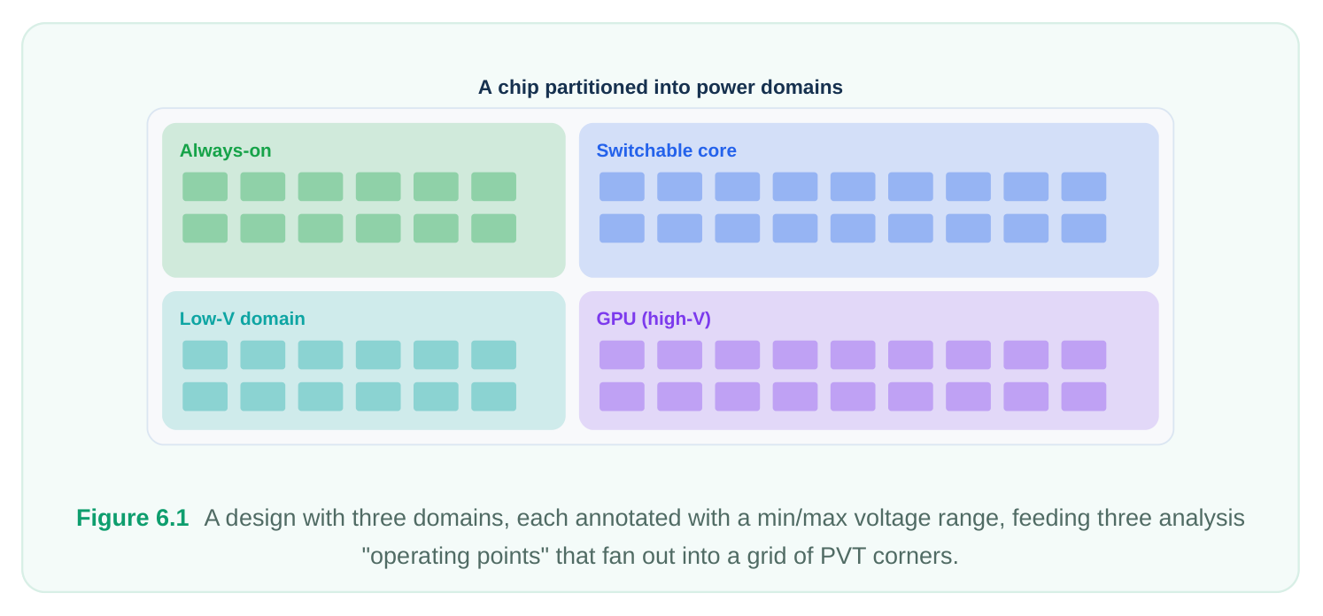
A multivoltage design is, by construction, a design that refuses to live at a single operating point. One block is tuned for raw throughput at a high rail, another idles at a frugal rail to save leakage, and a third may sleep entirely. Worse, modern parts do not even hold these rails fixed: a dynamic voltageand-frequency-scaling (DVFS) scheme slides a domain's voltage up and down at runtime to trade energy against performance. The consequence for the back end is unavoidable — there is no longer "the" timing run or "the" power number. The design must be proven correct across the full crossproduct of supply settings, process-voltage-temperature (PVT) conditions, and functional modes it will ever see in the field. This chapter is about how engineers describe that cross-product to the analysis engines, how they organize it so the optimizer can close it, and how the abstract power domains of the power intent become concrete rectangles of silicon with their own rails and guard cells. Get the bookkeeping wrong and you will tape out a chip that passes every report you looked at and fails the one corner you forgot.
Why one operating point is never enough
Consider the simplest interesting case: two domains, a fast CORE and a slow IO . If CORE can run at either 0.72 V (low-power) or 0.99 V (high-performance), and IO sits at a fixed 0.85 V, you already have two distinct voltage configurations of the same netlist. Each configuration changes cell delays, slew, leakage, and — crucially — the direction and necessity of the level shifters that bridge the two domains. A shifter that steps up when CORE is at 0.72 V may step down, or become redundant, when CORE climbs to 0.99 V. Now multiply by PVT. Slow-process / low-voltage / high-temperature stresses setup paths; fastprocess / high-voltage / low-temperature stresses hold paths and can also stress hold on a down- shifting boundary. Each domain contributes its own voltage axis, so the number of meaningful analysis points grows quickly. The job of operating-condition setup is to enumerate the points that matter — not all mathematically possible ones, but the realistic worst cases for each check — and hand them to the engines.
Operating conditions: voltage plus PVT
An operating condition binds three things together for an analysis run:
- 1. The process model (slow, typical, fast, or a statistical/derived variant).
- 2. The temperature the silicon is assumed to be at.
- 3. The voltage seen by each supply net the analysis cares about.
The third item is what distinguishes multivoltage flows from classic single-rail flows. Instead of one global voltage, the tool needs to know what each domain's primary supply is at this operating point. That value flows directly into delay calculation: the library characterization provides delay as a function of supply voltage, so telling the engine " VDD_CORE is 0.72 V here" selects (or interpolates) the right delay surface for every cell powered by that net.
| Axis | Stresses (setup) | Stresses (hold) | Typical low-power twist |
|---|---|---|---|
| Process | Slow | Fast | Same as classic flows |
| Voltage | Low rail | High rail | Each domain has its own rail value |
| Temperature | High (or low, in inversion) | Low (or high) | Temperature inversion common at low V |
| Domain state | Active, low rail | Active, high rail | A domain may also be off (no path) |
A subtlety worth internalizing: at the low voltages typical of power-saving modes, temperature inversion is real. Below a certain rail, a cell can actually be slower at low temperature than at high temperature, flipping the conventional intuition that "cold is fast." That is exactly why you cannot assume the hot corner is the only setup corner once domains scale down — you may need the coldand-low-voltage corner too.
Multi-corner multi-mode for low power
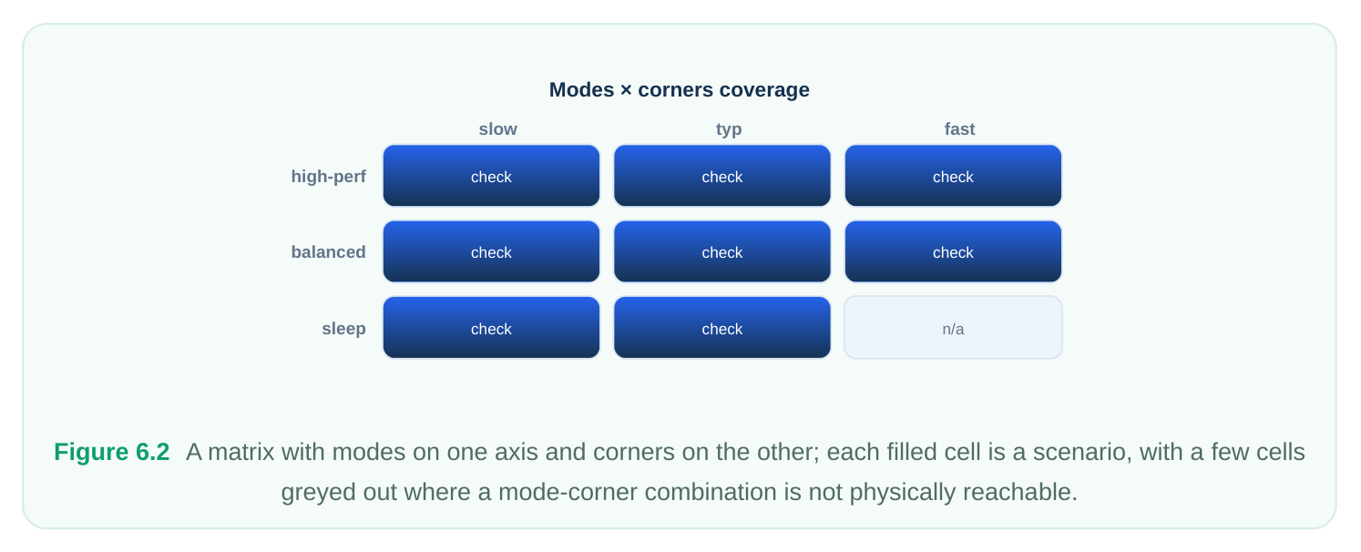
The discipline that organizes all of this is multi-corner multi-mode (MCMM). A corner is a PVT-plusvoltage operating condition together with its parasitic (RC) extraction. A mode is a functional configuration of the design: a set of timing constraints (clock periods, I/O timing, exceptions, active clocks) that describes how the chip is being used. A scenario is one corner paired with one mode — and a scenario is the unit the optimizer actually closes against. In a low-power design, modes map naturally onto power states. A high-performance mode runs the core fast and clamps nothing; a low-power mode slows the clock and drops core voltage; a sleep or retention mode shuts off whole domains, so their internal paths simply do not need timing analysis while their isolation and retention behavior does. The essential rule is that a fix must hold across every scenario simultaneously. You cannot resize a gate to fix a setup violation in the highperformance scenario if that same upsize creates a hold violation in the low-power scenario at a different rail.
| Mode | VDD_CORE | VDD_GPU | Clock target | Off domains | Dominant check |
|---|---|---|---|---|---|
| High-perf | 0.99 V | 0.95 V | 1.4 GHz | none | Core setup |
| Balanced | 0.85 V | 0.85 V | 900 MHz | none | Mixed |
| Low-power | 0.72 V | off | 400 MHz | GPU | Boundary + hold |
| Sleep | retention | off | gated | GPU, most of core | Iso/retention integrity |
Notice that the low-power and sleep modes both remove a domain. Their value to the flow is not in core timing but in proving that isolation clamps hold, retention registers keep state, and no live path tries to read a powered-down output. MCMM is therefore not just a performance-closure tool; it is how power-state correctness gets verified alongside timing.
Setting up operating points
Power intent in the IEEE 1801 standard lets you declare the legal voltage(s) a supply can take, and the analysis environment then references those when building each scenario. Conceptually you do three things: declare the supply nets and their allowed states, associate each domain's primary supply with a net, and then, per scenario, pin the voltage each net carries. The first block below sketches the intent side using generic, standard-style commands.
# Generic IEEE 1801-style power intent (vendor-neutral)
create_power_domain  PD_CORE
create_power_domain  PD_GPU  -elements {u_gpu}
# Declare supply nets and the voltage states each may take
create_supply_net    VDD_CORE -domain PD_CORE
create_supply_net    VDD_GPU  -domain PD_GPU
create_supply_net    VSS      -domain PD_CORE
# A supply set ties a power/ground pair together for a domain
create_supply_set    SS_CORE -function {power VDD_CORE} -function {ground VSS}
create_supply_set    SS_GPU  -function {power VDD_GPU}  -function {ground VSS}
# Enumerate legal supply states (voltage levels the rail may scale to)
add_power_state VDD_CORE -state {HV {voltage 0.99}} \
-state {NV {voltage 0.85}} \
-state {LV {voltage 0.72}}
add_power_state VDD_GPU  -state {ON {voltage 0.95}} \
-state {OFF {voltage off}}
The analysis side then turns those legal states into concrete operating points. The second block shows the operating-condition / scenario setup in a generic command style. The key actions are: set the voltage each supply net carries, attach a PVT library set, attach an extraction, and bundle the result into a named scenario tied to a mode's constraints.
# Generic analysis-environment setup (operating points + scenarios)
# 1. Define a mode = a set of timing constraints
create_mode  -name HIGH_PERF -constraints high_perf.sdc
create_mode  -name LOW_POWER -constraints low_power.sdc
# 2. Pin per-net voltages for an operating point, then a corner
set_voltage  VDD_CORE 0.99 -object_list [get_domain PD_CORE]
set_voltage  VDD_GPU  0.95 -object_list [get_domain PD_GPU]
set_operating_condition -process slow -temperature 125 -library slow_lib
create_corner   -name SLOW_HV -opcond current
create_scenario -name HP_SETUP -mode HIGH_PERF -corner SLOW_HV
# 3. A second operating point: core scaled down, GPU off, cold corner
set_voltage  VDD_CORE 0.72 -object_list [get_domain PD_CORE]
set_voltage  VDD_GPU  off  -object_list [get_domain PD_GPU]
set_operating_condition -process fast -temperature -40 -library fast_lib
create_corner   -name FAST_LV_COLD -opcond current
create_scenario -name LP_HOLD -mode LOW_POWER -corner FAST_LV_COLD
# 4. Activate the set the optimizer must satisfy together
set_active_scenarios {HP_SETUP LP_HOLD}
The pattern to remember: voltage is set per supply, per operating point. Forgetting to re-pin a domain's voltage when you change corners is one of the most common ways a "valid" scenario silently analyzes a domain at the wrong rail.
Voltage scaling groups: making rails track
Real silicon rarely scales one rail in perfect isolation. A regulator may feed several domains together, or two domains may be constrained by design to never differ by more than a fixed step (to keep a level shifter in its legal range). A voltage scaling group captures that relationship: it declares a set of supplies whose states move together, or in a defined ratio, across operating points. The practical reasons to use one:
- Shared regulator. If
VDD_COREandVDD_CACHEare driven by the same supply, it is physically impossible for them to sit at different voltages. The scaling group keeps the analysis honest — you never accidentally build a scenario with them mismatched. - Bounded boundary stress. Level shifters and the cells near a domain crossing have a characterized input/output voltage range. Grouping the two rails so their difference stays within that range prevents you from analyzing — or shipping — an illegal delta.
- DVFS tracking. When the system drops
VDD_COREfromNVtoLV, the group can force the dependent rails to a corresponding state automatically, so every operating point you generate is one the hardware can actually reach.
| Scaling-group behavior | What it guarantees | Failure it prevents |
|---|---|---|
| Locked-equal | Two rails always identical Bounded-delta | Mismatched-rail false corner V1 − V2 |
| Ratiometric | V2 = k·V1 | Inconsistent DVFS state |
From logical domain to physical voltage area
Everything so far has been logical: domains are groupings in the power intent. Physical implementation must turn each domain into a voltage area (also called a power region) — a contiguous piece of the floorplan reserved for that domain's cells, fed by that domain's own rails. The relationship is one of realization: the logical domain says "these cells share a supply and a power state"; the voltage area says "and here is the rectangle of die where they live, and the metal that delivers their rail." Why physical grouping is mandatory rather than optional:
- A domain that can be switched off needs its own switchable rail network. You cannot practically gate power to cells scattered randomly through a standard global rail; you fence them into a region whose rail is fed through power switches.
- Cells in the region must connect only to their domain's supply. Mixing a foreign rail into the region defeats the whole point and corrupts the power state assumptions.
- The boundary of the region is where the special cells live. The ring of the voltage area is where level shifters sit (to bridge the rail difference to neighbors), where isolation cells sit (to clamp outputs of a switchable region), and where the always-on buffers for control signals route through.
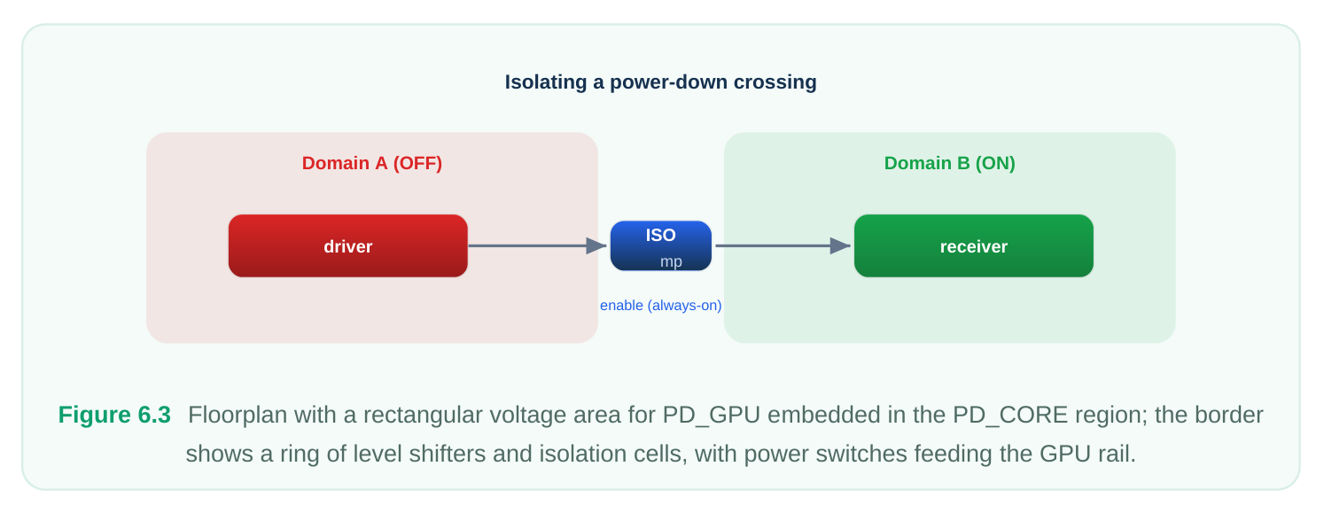
A useful mental check: the logical and physical views must agree at every boundary. If the power intent says a signal crosses from PD_CORE (0.99 V) into PD_GPU (0.95 V), then the physical voltage-area border that signal traverses must contain a level shifter of the correct direction, placed inside the appropriate region, with both its rails present. When the two views disagree, you get the classic boundary failures discussed next.
Pitfalls
The corner where a shifter flips direction. This is the single most dangerous omission in DVFS designs. Suppose a boundary normally steps down from CORE 0.99 V to IO 0.85 V, so you placed a down-shifter and you check it in the high-performance corner. In low-power mode the core scales to 0.72 V — now the same boundary is stepping up into 0.85 V, and your down-shifter is being asked to do the opposite job. If you never built the low-power operating point as a scenario, the analysis never sees the inverted condition and never flags that the cell is the wrong type or under-driven. Always enumerate the corner for each extreme of every scaling rail, specifically because shifter direction is voltage-dependent. Voltage mismatch at boundaries. A net that physically crosses two rails but lacks a level shifter (or has one of the wrong polarity) is a real electrical hazard, not a timing nuisance: it can sink crowbar current and degrade noise margins. These escape detection when an operating point is set up with both domains at the same voltage — the mismatch is invisible at that point. You must analyze a point where the rails genuinely differ for the boundary checks to bite. Stale voltage on a corner. Reusing a corner definition but forgetting to re-pin a domain's voltage leaves it at the previous operating point's value. The run completes cleanly and the numbers look plausible, which is exactly why it is dangerous. Treat every set_voltage as mandatory per operating point, and audit that each active scenario lists a voltage for every domain it touches. Ignoring temperature inversion. Closing setup only at the hot corner is correct for high rails but unsafe once a domain scales low, where cold can be the slow case. Add the cold-low-voltage scenario for any DVFS domain.
Interview Q&A
function of supply voltage, and different domains run at different — and scalable — rails. Each combination of domain voltages produces a different delay landscape, and on top of that you still have the usual PVT spread. A fix must be valid at every operating point simultaneously, so you analyze the realistic worst cases across the voltage and PVT axes rather than a single condition.
electrical condition: PVT plus per-rail voltage plus an RC extraction. A mode is a functional condition: a set of timing constraints describing how the chip is being used (clocks, exceptions, I/O timing). A scenario is one corner crossed with one mode, and it is the unit the optimizer actually closes. MCMM is the practice of closing across the chosen set of scenarios together.
grouping in the power intent that shares a supply and power state. The voltage area is its physical realization: a contiguous floorplan region fed by that domain's rails, with the special cells (level shifters, isolation, always-on buffers) ringing its boundary. The two must agree at every crossing — each signal that crosses a rail boundary logically must traverse a correctly placed, correctly powered special cell physically.
direction under DVFS. If a boundary steps down at the high core rail but the core can scale below the neighboring rail, the same boundary becomes an up-shift at the low rail. If you only built the highperformance operating point, you never analyze the inverted condition and miss that the shifter is the wrong type. The cold, low-voltage operating point is the matching scenario you must add, also because of temperature inversion.
Key Takeaways
- A multivoltage, DVFS-capable design has no single operating point; correctness is proven across a cross-product of per-domain voltages and PVT corners.
- An operating condition binds process, temperature, and the voltage of each supply net; that per-net voltage is what selects the right delay model for every cell.
- MCMM organizes the work into scenarios (corner × mode); a fix must hold across all active scenarios at once, and low-power modes also verify isolation and retention, not just timing.
- Voltage scaling groups keep related rails tracking — locked-equal, bounded-delta, or ratiometric — so you only ever build operating points the hardware can reach.
- A logical power domain becomes a physical voltage area: a fenced floorplan region with its own rails and a boundary ring of level shifters and isolation cells.
- The deadliest pitfalls are the unanalyzed corner where a shifter changes direction, true boundary voltage mismatches hidden by equal-rail setups, and stale voltages left on a reused corner. Enumerate the extremes of every scaling rail and re-pin voltage per point.
Comments
Leave a Reply