 ChipBuddy
← Home
ChipBuddy
← Home
Signal Integrity & Crosstalk
Signal Integrity and Crosstalk
A wire on a chip is not a perfect, lonely conductor. It sits close to many other wires. It has resistance, capacitance, and a little inductance. Because of these things, the signal that arrives at the far end is not a clean copy of the signal that left. Signal integrity (SI, keeping a signal clean as it travels along a wire) is the study of these effects and how to control them. When SI is poor, signals arrive late, arrive distorted, or pick up unwanted noise from neighbors. The biggest SI worry in modern chips is crosstalk (unwanted coupling of a signal from one wire onto another). This chapter explains where crosstalk comes from, how it slows or corrupts signals, and what designers do to fight it.
Coupling Capacitance and the Aggressor-Victim Model
Two wires running side by side act like the two plates of a small capacitor. Charge on one wire creates an electric field that reaches the other wire. This shared capacitance between neighbors is called coupling capacitance (the capacitance between two adjacent signal wires). When one wire switches voltage, that change couples through the capacitance and disturbs the neighbor. We give the two wires names. The aggressor (the wire that switches and causes the disturbance) is the one changing. The victim (the wire that gets disturbed) is the one that suffers.
A wire has two kinds of capacitance. One is the capacitance to the ground or substrate below, called ground capacitance. The other is the coupling capacitance to its neighbors. The ratio between them matters a lot. When coupling capacitance is a large share of the total, the wire is very sensitive to what its neighbors do.
Worked Example 1: Coupling ratio
A wire has:
Ground capacitance = 18 fF
Coupling capacitance to each of two neighbors = 22 fF each
Total coupling = 22 + 22 = 44 fF
Total capacitance = 18 + 44 = 62 fF
Coupling fraction = 44 / 62 = 0.71
71% of the wire's capacitance is to neighbors.
This wire is very exposed to crosstalk.
In older, wide-spaced chips, ground capacitance dominated. In modern chips wires are tall and thin and packed close, so coupling capacitance often dominates. That is why crosstalk has grown from a minor issue into a first-order design concern.
Crosstalk Delay: When Neighbors Change Your Timing
Crosstalk does not only add noise. It can change how fast a signal travels. This is crosstalk delay (a change in a wire's delay caused by a switching neighbor). The key idea is the effective capacitance the driver must charge. The voltage across the coupling capacitor decides how much charge moves through it. Three cases matter. When the aggressor is quiet, the victim driver charges the coupling capacitor through its normal voltage swing. This is the baseline case.
When the aggressor switches in the same direction as the victim, both ends of the coupling capacitor move together. Little charge needs to flow across it. The victim sees less effective capacitance and switches faster. When the aggressor switches in the opposite direction, the two ends move apart. Now the driver must push twice the voltage across the coupling capacitor. The victim sees more effective capacitance and switches slower.
| Aggressor behavior | Effective coupling cap | Victim delay |
|---|---|---|
| Quiet | 1x (nominal) | Nominal |
| Switches same direction | Near 0x | Faster |
| Switches opposite direction | Up to 2x | Slower |
This worst case, where the coupling capacitance looks doubled, is called the Miller effect (the apparent doubling of coupling capacitance when both ends swing in opposite directions).
Worked Example 2: Crosstalk delay swing
Victim driver resistance = 200 ohm
Ground capacitance = 18 fF
Coupling capacitance = 30 fF
Quiet aggressor effective cap = 18 + 30 = 48 fF
Delay (approx 0.69*R*C) = 0.69 * 200 * 48f = 6.6 ps
Opposite-switching aggressor cap = 18 + 2*30 = 78 fF
Delay = 0.69 * 200 * 78f = 10.8 ps
Delay grew from 6.6 ps to 10.8 ps, a 64% increase,
just because a neighbor switched the other way.
Timing tools must consider these cases. A path that meets timing with quiet neighbors might fail when neighbors switch against it.
Glitch Noise: When a Quiet Wire Gets a Bump
Now suppose the victim is supposed to stay still. It holds a steady logic level. The aggressor next to it switches. The coupling capacitor injects a sudden bump of charge onto the quiet victim. That bump is a glitch (a brief unwanted voltage pulse on a quiet wire).
How big the glitch gets depends on the coupling ratio and how strongly the victim is held. A weakly driven victim, or a long thin victim wire, sees a bigger bump. A strongly driven victim shorts the bump away quickly. A glitch is dangerous in two ways. First, if it reaches a logic threshold, downstream gates may briefly read the wrong value. Second, even a small glitch on a clock or a memory control line can cause a false trigger.
Worked Example 3: Glitch height
Coupling capacitance = 25 fF
Victim ground capacitance = 50 fF
Aggressor voltage swing = 0.9 V
Peak glitch (simple charge-share estimate):
Vglitch = Vswing * Ccoupling / (Ccoupling + Cground)
Vglitch = 0.9 * 25 / (25 + 50)
Vglitch = 0.9 * 25 / 75
Vglitch = 0.30 V
A 0.30 V bump on a 0.9 V supply is one third of the rail.
That is large enough to risk a wrong read downstream.
A common rule is to keep any glitch below some fraction of the supply, often around a fifth to a third of the rail, depending on how sensitive the receiving gate is.
Defenses: Spacing, Shielding, and Driver Strength
Designers have a toolbox of fixes. Most trade area or power for safety. The first fix is spacing (moving wires farther apart). Coupling capacitance drops as the gap grows. Doubling the gap on a sensitive wire can cut coupling sharply. The cost is wider routing channels and less room for other wires.
The second fix is shielding (placing a grounded or power wire between two signals). A shield wire ties to a steady voltage. It catches the field that would have reached the victim. The victim now couples to a wire that never moves, so it stays calm. The cost is the extra wire takes a routing track. The third fix is increasing victim driver strength (using a bigger driver so the wire is held firmly). A strong driver shorts away injected charge fast, so glitches stay small and delay pushout shrinks. The cost is more area and power in the driver. The fourth fix is reducing aggressor edge rate (slowing how fast the aggressor switches). A slower edge injects charge more gently. The cost is the aggressor signal itself gets slower.
| Defense | What it does | Main cost |
|---|---|---|
| Spacing | Lowers coupling cap | Routing area |
| Shielding | Blocks the field | Routing track |
| Stronger victim driver | Holds wire firmly | Power, area |
| Slower aggressor edge | Gentler injection | Aggressor speed |
| Net reordering | Avoids long parallel runs | Tool effort |
There is also a quieter fix called net reordering. Long parallel runs are the danger. If the tool staggers wires so they only run together briefly, total coupling drops without extra tracks.
Why Signal Integrity Worsens at Small Nodes
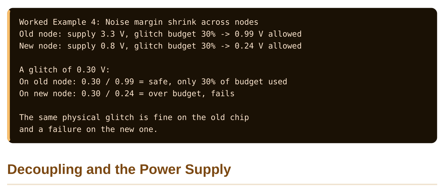
As process nodes shrink, SI gets harder, not easier. Several trends pile up. Wires get thinner and closer, so coupling capacitance grows as a fraction of total capacitance. Supply voltages drop, so the noise margin (how much noise a signal can take before it flips) shrinks. A 0.3 V glitch is harmless on a 5 V rail but serious on a 0.8 V rail.
Wire resistance also rises sharply at small dimensions, because a thin wire has a small cross-section. Higher resistance makes drivers weaker relative to the wire, so victims are held less firmly and glitches grow. Clock speeds rise too, so edges are faster and inject charge more abruptly.
So far we discussed wire-to-wire coupling. But the power supply itself is a shared resource, and noise on it spreads to everyone. When many gates switch at once, they all pull current from the supply at the same instant. The supply voltage dips. That dip is supply noise. The fix is decoupling capacitance (decap, small capacitors placed near the gates to supply quick bursts of charge). A decap sits between power and ground close to the load. When gates demand a sudden gulp of current, the decap hands it over locally instead of forcing the current down the long, resistive supply network.
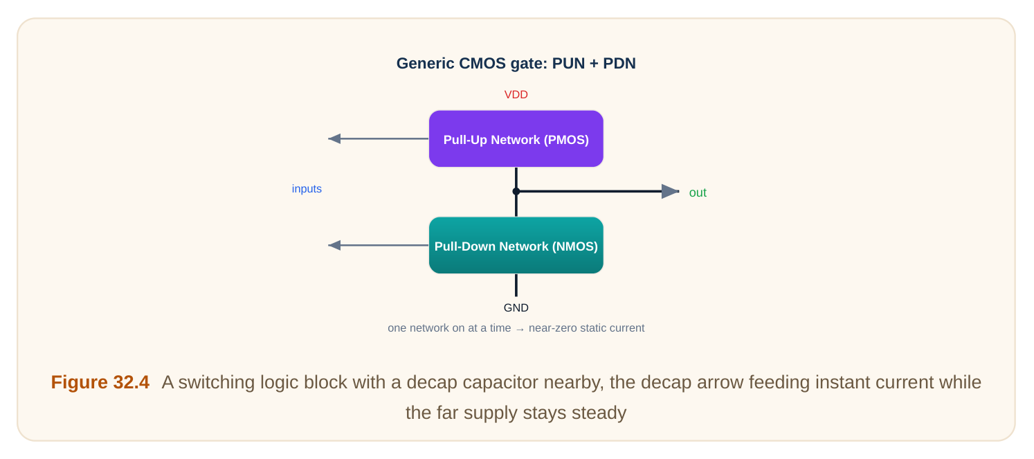
Decaps are scattered all over a chip, filling gaps in the layout. They cost area and add a little leakage, but they keep the local supply stable. A stable supply means cleaner edges, smaller glitches, and more predictable timing. So decoupling is really another SI tool, aimed at the supply rather than at signal wires.
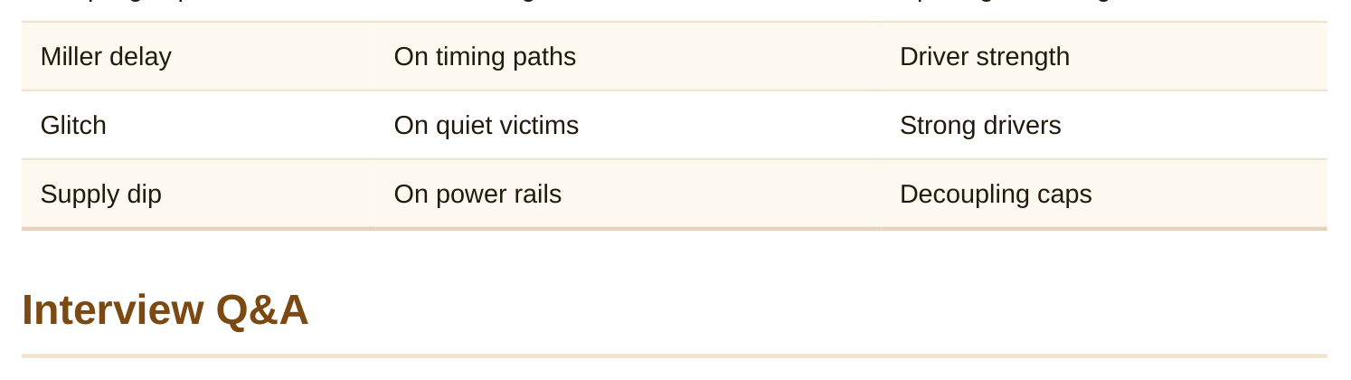
| Noise source | Where it appears | Main defense |
|---|---|---|
| Coupling cap | Between signal wires | Spacing, shielding |
switches voltage and creates the disturbance. The victim is the neighboring wire that gets disturbed through the coupling capacitance. The same wire can play either role at different times depending on which one is actively switching.
ends of the coupling capacitor swing apart, the driver must push twice the voltage across that capacitor. The coupling capacitance effectively looks doubled, called the Miller effect. The driver charges more effective capacitance, so the victim's edge takes longer.
that should stay steady. If the bump crosses a logic threshold, downstream gates briefly read the wrong value. On a clock or control line, even a small glitch can falsely trigger a register or memory.
between two signals. It intercepts the electric field that would have coupled to the victim. The victim now couples to a wire that never moves, so almost no disturbance reaches it.
coupling capacitance as a share of total. Supply voltage drops, so noise margins shrink and the same glitch is more harmful. Wire resistance rises and clocks speed up, so victims are held less firmly and edges inject charge faster.
power and ground near switching gates. When many gates draw a sudden burst of current, the decap supplies it locally so the long resistive supply network does not sag. A steady supply means cleaner edges and smaller glitches.
Key Takeaways
- Crosstalk comes from coupling capacitance between neighboring wires, modeled as an aggressor disturbing a victim.
- Crosstalk changes delay through the Miller effect, where opposite-direction switching can double the effective coupling capacitance and slow the victim.
- A switching aggressor can inject a glitch onto a quiet victim, risking wrong reads if the bump crosses a logic threshold.
- Spacing, shielding, stronger drivers, and slower edges all reduce crosstalk, each trading area, power, or speed.
- Decoupling capacitors stabilize the power supply so local current bursts do not cause supply dips that worsen signal integrity everywhere.
Comments
Leave a Reply