 ChipBuddy
← Home
ChipBuddy
← Home
Multi-Corner Multi-Mode (MCMM) Analysis
A real chip is not a single timing problem. It is dozens of them, all wearing the same silicon. The same flip-flops and gates that carry a high-speed functional clock must also behave during scan shift, during a low-power retention state, during a slow burn-in test, and they must do so whether the die came out hot or cold, whether the supply sagged or floated high, whether the transistors etched fast or slow. Each distinct way the design operates is a mode, and each distinct physical condition the silicon endures is a corner. Static timing analysis is only meaningful when it is qualified by both: timing closure means closure across the full cross product of modes and corners that the part is allowed to encounter in the field and on the tester. This chapter is about taming that cross product. We will define modes and corners precisely, explain why a single scenario at a time is both slow and dangerous, look at how concurrent multi-scenario analysis works, and walk through scenario reduction so you analyze the few combinations that matter rather than the many that do not.
The Combinatorial Reality
Suppose a design has four operating modes — functional, scan-shift, scan-capture, and a low-power mode — and you must sign off across five PVT corners. Naively, that is 4 × 5 = 20 separate timing
runs, each with its own constraints, libraries, and parasitics. Every one of those 20 is a scenario: a specific pairing of one mode with one corner. The design is only correct if all twenty pass their setup and hold requirements simultaneously. A failure in any single scenario is a failure of the chip.
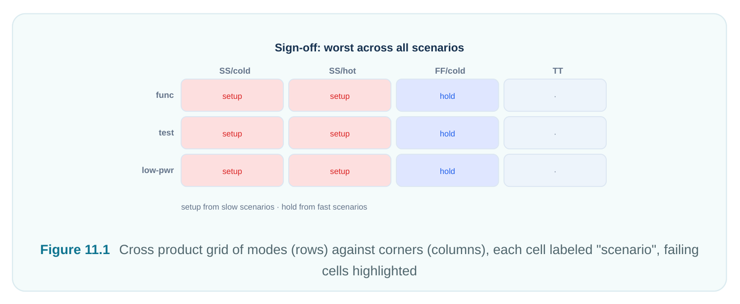
The combinatorial explosion is the central engineering problem of MCMM. As process nodes added more voltage rails, more on-chip variation models, and more test modes, the scenario count grew from a handful to many dozens. Managing this matrix — and pruning it intelligently — is what separates an efficient sign-off flow from one that runs for days and still misses a violation.
Modes Versus Corners
These two axes vary fundamentally different things, and conflating them is a classic source of confusion. A mode changes the electrical intent applied to the netlist: which clocks are active and at what frequency, what the I/O timing budgets are, which paths are declared false or multicycle, and what signals are tied to constants via case analysis. Two modes can share the exact same library and parasitics yet have completely different timing pictures because their constraints differ. A corner changes the physical characterization of the same netlist: the transistor process skew, the operating voltage, the junction temperature, and the extracted parasitic set (which itself depends on the metal RC corner). A corner says nothing about clocks or false paths — it only changes how fast or slow each gate and wire actually is. What it does NOT
Axis What it varies Typical examples
| Mode | SDC constraints: clock definitions, I/O | The physical | Functional, scan-shift, scan- |
|---|---|---|---|
| delays, case analysis, exceptions (false/ | libraries and multicycle) | capture, low-power/retention, parasitics | mission test |
| Corner | PVT: process skew, voltage, temperature, timing library, parasitic RC | The clocking and exception intent set | Slow-low-V-hot, fast-high-V-cold, typical-nominal, plus RC max/ min |
The cleanest mental model: a mode is a constraint set, a corner is a characterization set, and a scenario is one mode bound to one corner so that STA has everything it needs — a netlist, an intent (SDC), and a physics (libraries + parasitics) — to compute a complete set of path delays and slacks.
Why One Scenario at a Time Is Slow and Error-Prone
The historical flow ran each scenario as an independent session: read the netlist, read libraries for that corner, read the parasitic file for that corner, source the SDC for that mode, run a report, save, and repeat. This is wasteful and risky for several reasons. First, redundant work. The netlist parse, the connectivity build, and much of the timing-graph construction are identical across scenarios. Doing them twenty times wastes hours of runtime and gigabytes of memory churn. Second, constraint drift. When each mode's SDC lives in a separately maintained script, the same clock period gets defined slightly differently in two files, or a false path added for one mode silently disappears in another. The tool cannot warn you about an inconsistency it never sees in the same session. Third, fix conflicts. The most insidious problem. You close setup in the slow corner by upsizing a buffer. That same upsize makes a fast-corner hold path worse. If the two corners were analyzed in separate runs days apart, the engineer fixing setup never sees the hold damage they just caused. The result is endless ping-pong: fix A, break B, fix B, break A. Concurrent multi-scenario analysis solves all three. The netlist and timing graph are built once and shared; every scenario layers only its own delays and constraints on top. A single optimization engine can then see all slacks at once and choose a fix — a different cell, a smarter placement — that satisfies the worst setup scenario without breaking the worst hold scenario. That global view is the entire value proposition of MCMM.
Sign-Off Is the Worst Across All Active Scenarios
The sign-off rule is simple to state and easy to get wrong: for every endpoint, the reported slack is the minimum across all scenarios in which that endpoint is active. You do not average corners. You do not pick a representative scenario. The chip is governed by its worst case, endpoint by endpoint. This naturally splits by check type:
- Setup (max-delay) violations come from the slow scenarios — slow process, low voltage, high temperature for most logic — where paths take the longest and may miss the capture edge.
- Hold (min-delay) violations come from the fast scenarios — fast process, high voltage — where data races through and arrives too soon after the launch edge.
| Check | Dominant corner family | Physical reason | Failure symptom |
|---|---|---|---|
| Setup | Slow process, low V, hot (and slow-cold for some nodes) | Maximum gate and wire delay; data arrives late | Negative setup slack at capture |
| Hold | Fast process, high V, cold | Minimum delay; data arrives too early | Negative hold slack; data corrupts current cycle |
A subtlety worth knowing for interviews: at advanced nodes, temperature inversion means some cells are actually slowest at cold, not hot, so a thorough flow includes both slow-hot and slow-cold setup corners. Never assume one temperature extreme covers setup.
Scenario Reduction: Analyzing the Few That Matter
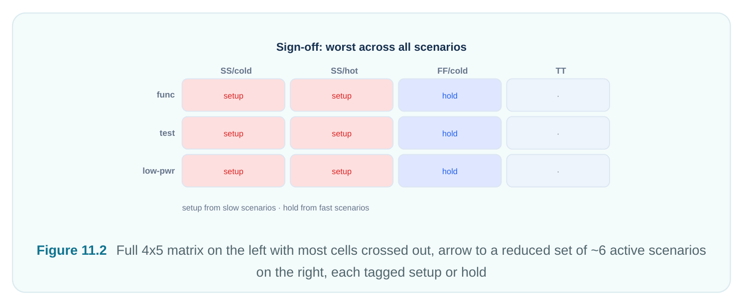
Running every mode against every corner is rarely necessary. Two observations let you prune the matrix safely. Not every mode runs at every corner. A scan-shift mode runs slowly on the tester, so it does not need the most aggressive high-frequency setup corner. A low-power retention mode has no functional clock toggling, so most setup corners are irrelevant to it. You analyze each mode only against the corners under which it can actually operate. Corners dominate one another. If corner X is slower than corner Y on every path, then any setup violation in Y is also caught in X — Y is dominated for setup and can be dropped. The same logic applies for hold among the fast corners. Dominance must be argued carefully (derating, parasitic corners, and temperature inversion can break a naive ordering), but when it holds it collapses the matrix dramatically. Reduction
Logic Effect on matrix
| Mode applicability | A mode that cannot run at a corner contributes | Removes whole rows from specific |
|---|---|---|
| no scenario there | columns | |
| Setup dominance | Keep only the slowest setup corner(s) that envelope the rest | Collapses many setup corners to one or two |
| Hold dominance | Keep only the fastest hold corner(s) | Collapses many hold corners to one |
or two
| Check-type | Each scenario flagged for the check it is meant | Avoids running hold in slow corners |
|---|---|---|
| pairing | to catch | and vice versa |
Setting Up Modes, Corners, and Scenarios
A modern MCMM flow expresses the three ingredients separately and then composes them. The commands below are illustrative — generic, not tool-specific — to show the structure; the SDC fragments they reference are standard. A mode bundles the SDC that describes one operating intent:
# illustrative -- generic, not tool-specific
define_mode functional -sdc { clk_func.sdc io_func.sdc exceptions_func.sdc }
define_mode scan_shift -sdc { clk_shift.sdc scan_constraints.sdc }
define_mode low_power  -sdc { clk_lp.sdc retention.sdc }
A corner bundles the physics — the characterized libraries plus the matching parasitics:
# illustrative -- generic, not tool-specific
define_corner ss_low_hot \
-libs   { stdcell_ss_0p72v_125c.lib mem_ss_0p72v_125c.lib } \
-parasitics rc_max.spef \
-intent setup
define_corner ff_high_cold \
-libs   { stdcell_ff_0p88v_m40c.lib mem_ff_0p88v_m40c.lib } \
-parasitics rc_min.spef \
-intent hold
A scenario pairs one mode with one corner and tells the engine which check it is responsible for:
# illustrative -- generic, not tool-specific
create_scenario func_setup -mode functional -corner ss_low_hot  -check setup
create_scenario func_hold  -mode functional -corner ff_high_cold -check hold
create_scenario shift_setup -mode scan_shift -corner ss_low_hot  -check setup
create_scenario shift_hold  -mode scan_shift -corner ff_high_cold -check hold
set_active_scenarios { func_setup func_hold shift_setup shift_hold }
analyze_timing -all_active_scenarios
The mode SDC itself is ordinary, standard syntax. What makes it a mode is simply that it is grouped and bound to scenarios rather than sourced globally:
# standard (SDC)
# --- contents of clk_func.sdc, the functional mode's clock intent ---
create_clock -name clk_core -period 2.000 [get_ports clk]
set_input_delay  0.400 -clock clk_core [get_ports {data_in[*]}]
set_output_delay 0.350 -clock clk_core [get_ports {data_out[*]}]
set_false_path -from [get_ports test_en]
Contrast that with the shift mode, whose clock is slower and whose scan enable is no longer a false path:
# standard (SDC)
# --- contents of clk_shift.sdc, the scan-shift mode's intent ---
create_clock -name clk_core -period 10.000 [get_ports clk]
set_case_analysis 1 [get_ports scan_mode]
set_multicycle_path 2 -setup -through [get_pins scan_chain_reg*/SI]
The same port clk carries a 2 ns period in functional mode and a 10 ns period in shift mode — a perfect illustration of why the mode (constraint set) is independent of the corner (physics).
A Worked Scenario Matrix
Let us make it concrete. Take three modes — Functional (FUNC), Scan-Shift (SHIFT), Low-Power (LP) — and four corners: SS_LV_HOT and SS_LV_COLD as setup candidates, FF_HV_COLD as the hold candidate, and TT_NOM as a typical reference. Start from the naive 3 × 4 = 12 cells, then apply reduction:
| Mode \ Corner | SS_LV_HOT (setup) | SS_LV_COLD (setup) | FF_HV_COLD (hold) | TT_NOM (ref) |
|---|---|---|---|---|
| FUNC | Active (setup) | Active (setup) | Active (hold) | dropped |
| SHIFT | Active (setup) | dropped (envelope) | Active (hold) | dropped |
| LP | dropped (no func clk) | dropped | Active (hold) | dropped |
Reasoning behind each decision:
- FUNC is the speed-critical mode, so it keeps both setup corners (because of temperature inversion we cannot assume hot dominates cold) plus the hold corner. That is three active scenarios.
- SHIFT runs at a relaxed 10 ns period; one slow setup corner envelopes the other for this low- frequency mode, so we keep a single setup scenario. It still needs hold checking because hold is frequency-independent. That is two active scenarios.
- LP has no toggling functional clock, so setup is moot. Hold across the fast corner must still be honored for any always-on or retention logic. That is one active scenario.
- TT_NOM is a correlation reference, not a sign-off corner; no scenario uses it for closure. The twelve-cell naive matrix collapses to six active scenarios — three setup, three hold — a 50% reduction with zero loss of coverage. On larger designs the savings are far steeper, often turning 60+ naive combinations into 8–12 real sign-off scenarios. The closure discipline then follows the worst-case rule. For an endpoint exercised in FUNC, its setup slack is
min(slack@SS_LV_HOT, slack@SS_LV_COLD)and its hold slack isslack@FF_HV_COLD. An endpoint that is also a scan element inherits the SHIFT hold scenario too, so its final hold slack is the minimum over both hold scenarios in which it participates. You never sign off on any single scenario in isolation.
Interview Q&A
corner. How does MCMM help, and what would you have missed without it? In a concurrent MCMM session the optimizer sees the slow-corner setup slack and the fast-corner hold slack at the same endpoint simultaneously, so it can pick a fix — different cell, different placement, or a hold buffer placed where it does not hurt setup — that satisfies both at once. Without MCMM, the two corners are separate runs; you fix setup, declare victory, and only discover the hold break days later in a different session, leading to fix ping-pong. The core lesson is that setup and hold corners are coupled and must be optimized together.
of SDC constraints describing how the chip operates — its clocks, I/O budgets, case analysis, and exceptions. A corner is a set of physical characterizations — process, voltage, temperature, libraries, and parasitics — describing how fast the silicon actually runs. A scenario binds one mode to one corner so STA has both intent and physics.
to drop? Almost never. First apply mode applicability — a slow tester mode does not need the highfrequency setup corner, a retention mode needs no setup corner at all. Then apply corner dominance — keep only the slowest setup corner(s) and fastest hold corner(s) that envelope the rest, being careful about temperature inversion and parasitic corners that can break a naive ordering. Tag each surviving scenario with the check it owns. Forty often reduces to a single-digit count of real sign-off scenarios.
whole story? Setup is driven by slow scenarios — slow process, low voltage, high temperature — where paths are longest and may miss the capture edge. Hold is driven by fast scenarios — fast process, high voltage, cold — where data arrives too early. The nuance is temperature inversion at advanced nodes: some cells are slowest cold, not hot, so a robust setup sign-off includes both slowhot and slow-cold corners rather than assuming one temperature extreme envelopes the other.
Key Takeaways
- A chip must satisfy timing across the cross product of every operating mode and every PVT corner; each mode×corner pair is a scenario, and all active scenarios must pass.
- A mode is a constraint set (clocks, I/O, case analysis, exceptions); a corner is a characterization set (PVT, libraries, parasitics). Keep the two axes conceptually distinct.
- Running one scenario at a time wastes runtime and, worse, hides cross-corner fix conflicts; concurrent multi-scenario analysis builds the timing graph once and lets the optimizer see all slacks together.
- Sign-off slack is the worst across all active scenarios per endpoint — setup from the slow scenarios, hold from the fast ones — never an average or a single representative run.
- Scenario reduction via mode applicability and corner dominance collapses a large naive matrix into a small set of real sign-off scenarios with no loss of coverage — but watch for temperature inversion and parasitic corners that break naive ordering.
- Express modes, corners, and scenarios as separate, composable objects so SDC stays consistent and the matrix is easy to audit and prune.
Comments
Leave a Reply