 ChipBuddy
← Home
ChipBuddy
← Home
Timing Paths, Arrival/Required & Slack
Static timing analysis (STA, checking chip speed without running it) asks one question. Does the signal arrive on time? The tool asks this at millions of points. This chapter explains the pieces behind that question. Those pieces are paths, startpoints, endpoints, arrival times, required times, and slack. Once you understand a path and slack, the rest is simple bookkeeping.
What a timing path is
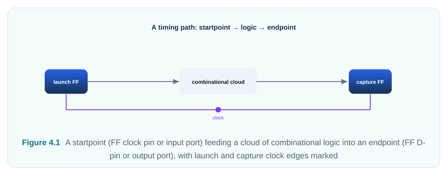
A timing path is a route through the design. A signal change travels along it in one clock cycle. The path starts at a startpoint (where data begins). It runs through combinational logic (gates and wires with no memory). It ends at an endpoint (where data must arrive). The tool walks the route and adds up delays. Then it compares the total to the time the clock allows. A startpoint is one of two things. It is a primary input port (a signal entering the block). Or it is the clock pin of a sequential element (a flip-flop or latch, a one-bit memory). Both launch data at a known instant. An endpoint is also one of two things. It is a primary output port (a signal leaving the block). Or it is the data input pin (D) of a sequential element (where data is stored). Combinational logic never starts or ends a path. It only sits in the middle. So a path always runs from a launch point to a capture point. The job is to see if the trip fits in the time window.
The four canonical path groups
Each startpoint is one of two kinds. Each endpoint is one of two kinds. So there are exactly four combinations. STA tools sort paths into these four groups. Each group has a different outside assumption. Engineers like to look at them one at a time.
| Path group | Startpoint | Endpoint | Constrained by |
|---|---|---|---|
| Input-to-register (in2reg) | Primary input | Register D-pin | set_input_delay |
port
| Register-to-register | Register clock | Register D-pin | The clock period only |
|---|---|---|---|
| (reg2reg) | pin | ||
| Register-to-output | Register clock (reg2out) | Primary output pin | set_output_delay port |
| Input-to-output (in2out) | Primary input port | Primary output port | Both input and output delay (pure combinational) |
The reg2reg group is the core of a synchronous design. The clock alone constrains it. No extra setting is needed. Both ends sit on clock edges the tool already knows. The in2reg and reg2out groups touch the block boundary. They depend on the outside world. We must say how late an input comes. We must say how early an output must be ready. These come from input and output delay settings. The in2out group has no register on either end. It is pure logic, a feed-through. It is the least common group. But we still budget it so the block fits with its neighbors. A good habit helps here. When a report shows a violation, find its group first. That tells you where the fix lives. A reg2reg fix lives inside your block. A boundary-group fix lives at the contract with the rest of the system.
Arrival time: propagating forward
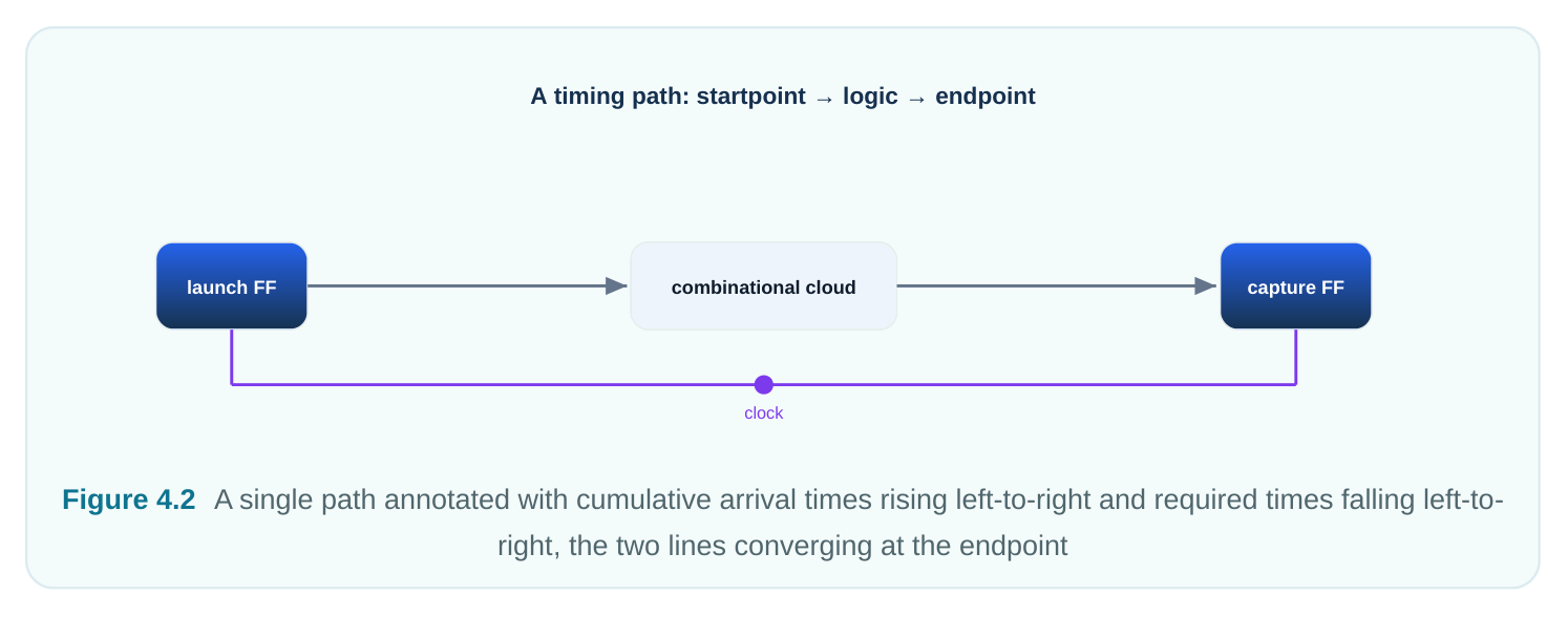
The arrival time at a node is the real time a signal change reaches it. We measure it from a clock reference. The tool walks forward to find it. It starts at the launch point. At each gate it adds the gate's
delay. It also adds the wire (net) delay coming in. Arrival time only grows as you move downstream. Each gate makes the signal a bit later. The starting value is usually not zero. Take a register-to-register path. Data launches when the launch clock edge reaches the source flip-flop's clock pin. That is the clock network delay. Then add the flipflop's clock-to-Q delay (output appears after the edge). For an input-to-register path, data launches at the set input delay. After that, logic delays pile on. The arrival time at the endpoint answers one thing. When does data really show up at the D-pin? Real gates and wires have a slowest and a fastest delay. So each node has two arrival times. The late (max) arrival uses the biggest delays. The early (min) arrival uses the smallest delays.
Required time: propagating backward
The required time at a node is a deadline. It is the latest a signal may arrive without breaking a rule. For hold it is the earliest. The tool walks backward from the endpoint to find it. At the endpoint the rule comes from the capture event. Data must be stable before the capture edge. We subtract the flip-flop's setup time. We also adjust for clock network delay on the capture side. Then we walk backward through the logic. We subtract each gate's delay. This gives the required time one stage earlier. Required time shrinks as you move upstream. Earlier nodes must finish sooner. That way downstream logic still has time. One model keeps the two straight. Arrival is a fact pushed forward. It says when the signal will arrive. Required is a deadline pushed backward. It says when the signal must arrive. They meet at every node. The gap between them is the whole point.
| Aspect | Arrival time | Required time |
|---|---|---|
| Meaning | When the signal actually gets there | When it is allowed to get there |
| Propagation direction | Forward, from startpoint | Backward, from endpoint |
| Per-gate operation | Add delay | Subtract delay |
| Anchored at | Launch edge + clock-to-Q (or input delay) | Capture edge − setup (or + hold) |
| Trend along path | Increases downstream | Decreases upstream |
Slack: the verdict
Slack is required time minus arrival time. It is one number. It tells you if a path passes or fails. It also tells you by how much. For setup (max-delay) analysis:
slack(setup) = required_time − arrival_timeFor hold (min-delay) analysis the order flips. Hold is about data arriving too early. Early data can corrupt the value being captured on this edge.
slack(hold) = arrival_time − required_timeIn both cases the meaning is the same. Positive slack means the rule is met with room to spare. Zero slack means it is met exactly. That path is critical. Negative slack means a violation. Here is a line worth memorizing. Setup wants data early enough; required must beat arrival. Hold wants data late enough; arrival must beat required. Fix setup by making logic faster or relaxing the period. Fix hold by adding delay. Hold fixes do not depend on clock frequency.
| Slack value | Setup interpretation | Hold interpretation |
|---|---|---|
| Positive (> 0) | Data settles before deadline; margin exists | Data held long enough after the edge; safe |
| Zero (= 0) | Exactly meets setup; this is the critical path | Exactly meets hold |
| Negative (< 0) | Data arrives too late; setup failure | Data changes too soon; hold failure |
Max vs min, and why both directions are always computed
You may think only the slowest path matters. But timing closure needs two opposite checks. They run on the same hardware.
Max (setup / late) analysis uses the biggest delays. It checks that data arrives before the next capture edge. This sets how fast you can clock the design. If the slowest path cannot finish in one period, you must lower the frequency. Min (hold / early) analysis uses the smallest delays. It checks that data does not arrive too soon. Too-soon data races through. The same edge that launched it could capture it. That overwrites the old value before it was stored safely. Hold has nothing to do with clock period. Even a very slow clock will not fix a hold violation. The failing window sits around a single edge. That is why running the part slower in the lab does not help. Both checks are needed. A path can be safe for setup yet fail hold. A very short logic path between two flops on the same clock is the classic case. The reverse can also happen. So the tool runs the forward and backward walk twice. Once with max delays. Once with min delays. It reports slack for each. Setup (next edge) vs hold (same edge)
| Setup check | Hold check | |
|---|---|---|
| launch | capture (T) | same edge |
| data must arrive before T −Tsu | data must NOT arrive before Thold |
Figure 4.3 Same flop-to-flop path shown twice — top with max delays checked against the next edge for setup,
bottom with min delays checked against the same edge for hold
Critical paths, and why STA reports the worst per endpoint
A real design has a huge number of distinct paths. Fan-in and fan-out make paths multiply. The count can reach billions. STA does not list them all. Instead it computes arrival and required times at every node once. This work grows with the size of the graph, not the number of paths. Then it reports the worst slack at each endpoint or group. The critical path has the smallest setup slack in the whole design. It sets the top operating frequency. By default the tool shows the single worst path per endpoint. If the worst path passes, every other path to that endpoint passes too. You can ask for the top N paths per endpoint during debug. Two summary metrics roll this up:
- WNS (Worst Negative Slack): the single worst slack across all endpoints. If WNS ≥ 0, the design meets timing. It tells you how badly the worst point fails.
- TNS (Total Negative Slack): the sum of all negative slacks across endpoints. Positive slacks count as zero. It tells you how many points fail. It shows how widespread the problem is. Say WNS is −0.2 ns but TNS is −60 ns. That means thousands of small failures. That is a very different repair job than one big outlier.
A worked slack example
Let us compute setup slack for one register-to-register path. We use fresh, invented numbers. The clock period is 2.50 ns. The launch and capture flops share the same clock.
| Quantity | Value (ns) | Notes |
|---|---|---|
| Clock period (T) | 2.50 | Capture edge one period after launch |
| Launch clock network delay | 0.40 | Clock reaching the source flop |
| Source clock-to-Q delay | 0.20 | Flop output after the edge |
| Combinational logic delay (max) | 1.30 | Sum of gate + net delays |
| Capture clock network delay | 0.45 | Clock reaching the destination flop |
| Destination setup time | 0.18 | Stability required before capture |
Arrival time at the endpoint (D-pin): arrival = launch clock delay + clock-to-Q + combinational delay arrival = 0.40 + 0.20 + 1.30 = 1.90 ns Required time at the endpoint: required = (period + capture clock delay) − setup required = (2.50 + 0.45) − 0.18 = 2.77 ns Setup slack: slack = required − arrival = 2.77 − 1.90 = +0.87 ns The slack is positive. So the path passes with 0.87 ns to spare. Notice the capture clock delay. It adds to the required time. That gives this path more time. That is useful skew when it helps you. It also shows why clock delays must be modeled well. An error of a few tenths of a nanosecond can flip a pass into a fail.
Code: reporting a path and setting path-group reporting
The first block reports the worst path. Then it reports the worst path per group. It uses standard SDCstyle queries.
# standard (SDC)
# Worst overall setup path in the design
report_timing -delay_type max -max_paths 1
# Worst hold path
report_timing -delay_type min -max_paths 1
# Worst path landing on a specific endpoint register
report_timing -to [get_pins core/acc_reg[3]/D] -delay_type max
The second block makes custom path groups. Boundary paths and internal paths get reported apart. It then asks for several paths per group during debug. These grouping commands follow a common
SDC idiom. The exact group-creation syntax varies by flow. So treat the group definitions as illustrative.
# illustrative — generic, not tool-specific
# Separate the four canonical interactions into named groups
group_path -name IN2REG  -to   [all_registers -data_pins]
group_path -name REG2OUT -from [all_registers -clock_pins]
group_path -name IN2OUT  -from [all_inputs] -to [all_outputs]
# Report the 5 worst paths in each group, with full delay annotation
report_timing -group {IN2REG REG2OUT IN2OUT} \
-max_paths 5 -nworst 5 -delay_type max
Interview Q&A
Setup and hold check opposite extremes on the same path. Setup uses the maximum delay. It asks if data arrives before the next edge. Hold uses the minimum delay. It asks if data arrives after the current edge plus a margin. A short, fast logic path between two flops can meet setup easily. Yet it can fail hold. Data races through and reaches the capture flop too soon. The fix is to add delay on the data path. Use buffers or delay cells. Or manage clock skew. Slowing the clock does nothing for hold. The hold window is local to a single edge.
fan-in and fan-out. It is often in the billions. STA avoids that. It computes arrival and required times at each node once. It uses forward and backward graph walks. This work is linear in the circuit size. The worst slack at any endpoint comes from those node values. The tool never lists the individual paths. It then reports the worst path, or worst N, per endpoint or group. If the worst passes, the rest do too.
slack in the design. It answers two things. How bad is the worst point? What frequency can I run at? TNS sums all negative slacks. It answers how pervasive the problem is. You need both. They describe different repair jobs. A tiny WNS with a huge TNS means many small, widespread failures. That often points to a global issue, like an over-optimistic clock or a constraint error. A large WNS with small TNS points to one or a few local critical paths. You attack those directly.
time is pushed forward from the startpoint. You add clock-to-Q and every gate and net delay. That gives the real time data reaches the D-pin. Required time is pushed backward from the capture event. Take the capture edge time. Adjust for capture clock delay. Subtract the setup time. Setup slack is required minus arrival. Positive means data settles before its deadline. For hold the order flips to arrival minus required. The worry there is data arriving too early, not too late.
Key Takeaways
- A timing path runs from a startpoint (input port or register clock pin) through combinational logic to an endpoint (output port or register D-pin). The four groups are in2reg, reg2reg, reg2out, and in2out.
- Arrival time is pushed forward, adding delays. It says when a signal really arrives. Required time is pushed backward, subtracting delays. It states the deadline.
- Slack = required − arrival for setup. Slack = arrival − required for hold. Positive passes, negative fails, zero is exactly critical.
- Max/setup analysis uses the biggest delays and the next edge. It bounds clock frequency. Min/ hold analysis uses the smallest delays and the same edge. It catches data races and is independent of period. Both are always computed.
- STA reports the worst path per endpoint or group. It does not list billions of paths. WNS captures the worst single failure. TNS captures how widespread failures are.
- Clock network delays on the capture side add to required time. They shift slack a lot. Model them well; do not assume zero.
Comments
Leave a Reply