 ChipBuddy
← Home
ChipBuddy
← Home
Multicycle, Half-Cycle & Edge-Selection Cases
Chapter 19 — Multicycle, Half-Cycle & Edge-Selection Corner
Cases (Deep)
A multicycle path (MCP) means "this path is allowed more than one clock cycle." The idea is simple. The trouble is the edge bookkeeping (which clock edge the tool uses) underneath it. The tool's default behavior rarely matches what the designer pictures. The most common silent bug is a setup MCP with no matching hold MCP. This quietly turns a relaxed setup path into an impossible hold check. This chapter rebuilds the machinery edge by edge. You will learn to write these exceptions correctly. You will also learn to explain, in an interview, why the default hold check lands in the wrong place.
Recap: what a multicycle path actually is
By default, one register-to-register path gets one clock period for setup. Data launched at edge k must be captured at edge k+1. The hold check is its companion. Data must not race ahead and corrupt the value held from the launch edge. By default the hold capture edge is edge k (zero cycles of separation). A multicycle path tells the tool the logic does not need a result every cycle. Maybe a slow datapath produces a valid result only every third clock, gated by an enable (a signal that says "use this now"). We then relax setup so the path gets N periods to settle.
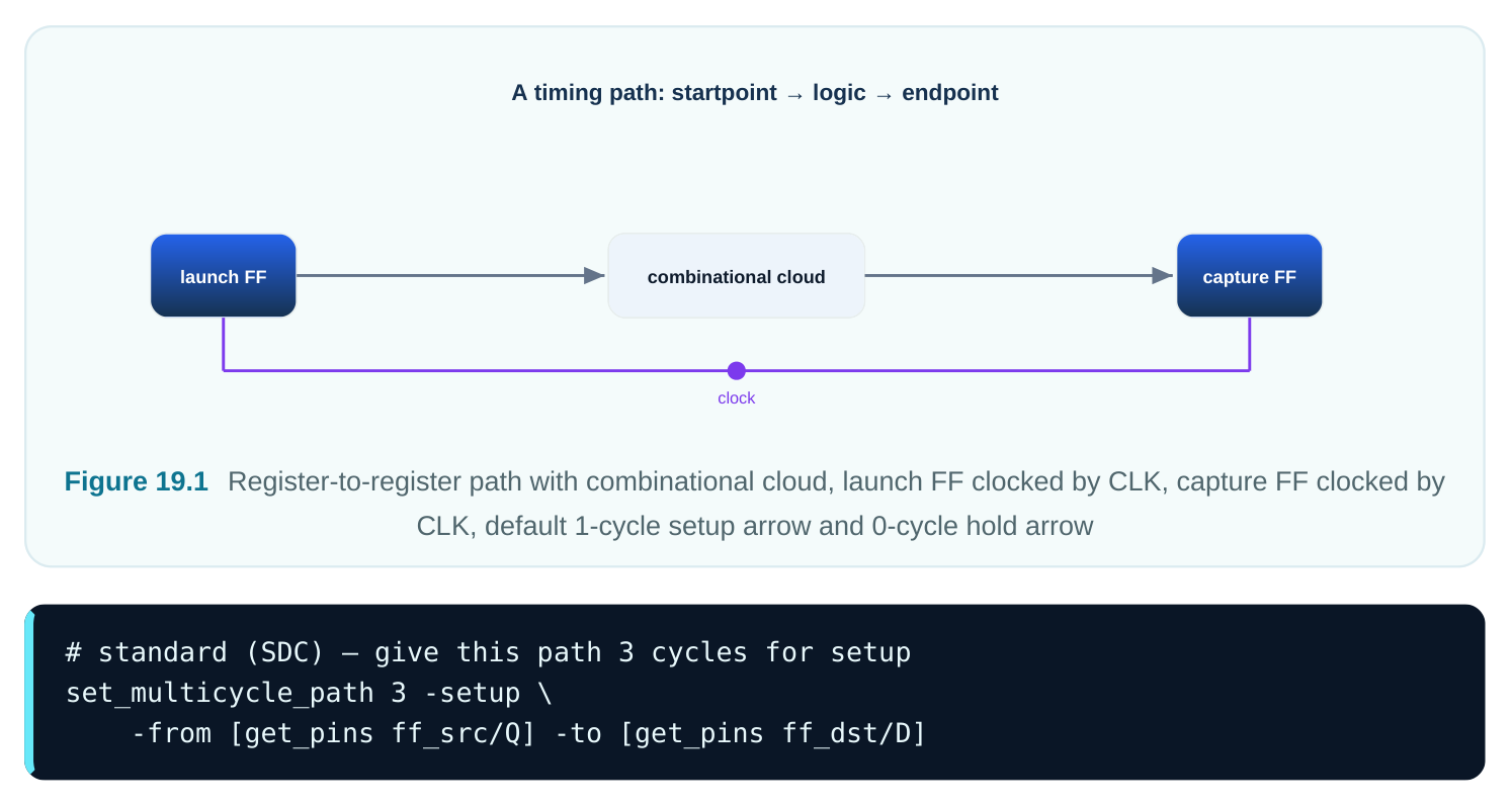
The number is the capture-edge multiplier. -setup 3 means: capture at the third edge after launch, not the first. So far so good. The trap is what the tool now does to the hold check.
The classic trap: setup MCP moves hold with it
Here is the rule that catches everyone. The hold check always sits one capture period before wherever setup lands. Push setup out to edge N, and the default hold check follows to edge N−1. That is almost never what you want. You relaxed setup because the data is slow and changes rarely. But the default hold now demands the data hold stable through edge N−1. That is nearly N full periods. No normal path can do that. It would need huge added delay. The fix is a hold multicycle of N−1. This pulls the hold edge back to edge 0 (the launch edge). The normal "don't race past your own launch" hold check returns.
# standard (SDC) — the correct multicycle PAIR
set_multicycle_path 3 -setup -from [get_pins ff_src/Q] -to [get_pins ff_dst/D]
set_multicycle_path 2 -hold  -from [get_pins ff_src/Q] -to [get_pins ff_dst/D]
The rule: hold multiplier = setup multiplier − 1 for a same-frequency, single-clock multicycle. Learn this rule and its reason. You have then answered half the multicycle questions any interviewer asks.
| Quantity | Default (no MCP) | Setup MCP = 3, no hold MCP | Setup MCP = 3 + hold MCP = 2 |
|---|---|---|---|
| Setup capture edge | 1 | 3 | 3 |
| Hold capture edge | 0 | 2 | 0 |
| Setup window given | 1 period | 3 periods | 3 periods |
| Hold requirement | normal | ~2 periods of hold (broken) | normal |
| Realistic? | yes | no | yes |
Worked timeline 1 — setup MCP = 3, hold MCP = 2
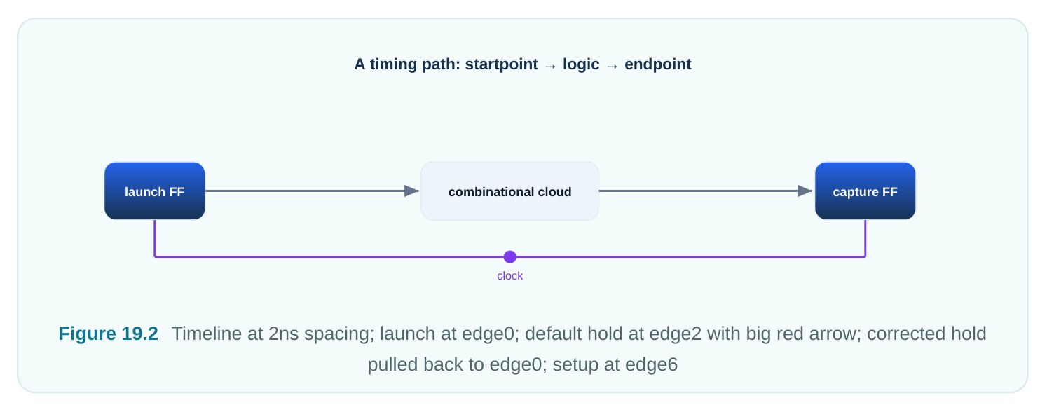
Let the clock period be T = 2.5 ns. Edges fall at t = 0, 2.5, 5.0, 7.5, 10.0 ns. Both registers use the same positive-edge clock. Launch happens at edge 0. Setup (without hold MCP): the capture edge moves from edge 1 (t = 2.5) to edge 3 (t = 7.5). The setup equation becomes:
Required time (setup) = capture_edge - Tsetup = 7.5 - 0.12 = 7.38 ns
Data arrival          = launch_edge + Tcq + Tlogic = 0 + 0.18 + 6.90 = 7.08 ns
Setup slack           = 7.38 - 7.08 = +0.30 ns   (pass)
The path got nearly 7.5 ns to resolve instead of 2.5 ns. That is the relaxation we wanted. Default hold (the broken one): the hold capture edge = setup edge − 1 = edge 2 (t = 5.0).
Required time (hold) = hold_capture_edge + Thold = 5.0 + 0.06 = 5.06 ns
Data arrival (fast)  = launch_edge + Tcq + Tlogic_min = 0 + 0.18 + 0.25 = 0.43 ns
Hold slack           = 0.43 - 5.06 = -4.63 ns   (catastrophic FAIL)
The tool now thinks the data must stay stable until 5.06 ns. That is two full periods after launch. It makes no sense for a normal datapath. Left alone, an optimizer would pad this path with about 4.6 ns of buffering and wreck it. With hold MCP = 2: the hold capture edge is pulled back by 2 periods, to edge 0 (t = 0):
Required time (hold) = 0.0 + Thold = 0.06 ns
Data arrival (fast)  = 0.43 ns
Hold slack           = 0.43 - 0.06 = +0.37 ns   (pass)
Sane again. This is the normal, single-cycle hold check. The pair -setup 3 / -hold 2 is the correct, complete constraint.
Half-cycle paths: half a period, easy to miss
A half-cycle path launches on one clock edge and captures on the opposite edge. That is rise to fall, or fall to rise. The path gets only half a clock period for setup. These are the opposite danger from multicycles. Here you can accidentally over-constrain, not under-constrain. They tighten the requirement and are easy to miss. They show up from:
- Negative-edge flops capturing data from a positive-edge flop, or the reverse.
- Both-edge logic like DDR interfaces, dual-edge sampling, or clock-divider feedback.
- Latch-based timing where transparency boundaries fall on opposite phases. The key point: the tool picks the nearest capture edge after launch. For a positive-edge launch into a negative-edge capture, the nearest capturing (negative) edge is only T/2 away. That is half a period of setup budget. Path type Launch edge Capture edge Setup budget Hold reference Normal rise next rise T same rise (0) Half-cycle (rise→fall) rise @ 0 fall @ T/2 T/2 fall @ −T/2 Half-cycle (fall→rise) fall @ T/2 rise @ T T/2 rise @ 0 Multicycle N rise @ 0 rise @ N·T N·T per hold MCP
Worked timeline 2 — a half-cycle path
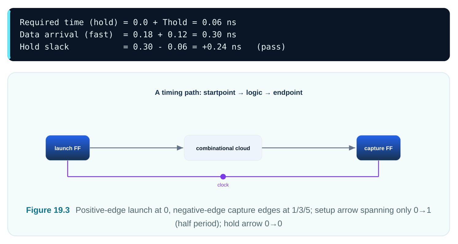
Same clock, T = 2.5 ns, 50% duty cycle. The launch FF is positive-edge and launches at t = 0. The capture FF is negative-edge, so its capturing edges fall at t = 1.25, 3.75, 6.25 ns. The nearest capture edge after t = 0 is t = 1.25 ns. That is only half a period.
Setup capture edge   = 1.25 ns
Required time (setup)= 1.25 - Tsetup = 1.25 - 0.12 = 1.13 ns
Data arrival         = 0 + Tcq + Tlogic = 0.18 + 0.75 = 0.93 ns
Setup slack          = 1.13 - 0.93 = +0.20 ns   (pass, but tight)
Notice the same logic with 0.75 ns of delay. In a normal full-cycle path it would have about 1.45 ns of slack. Here it has only 0.20 ns. Half-cycle paths are unforgiving. A logic cloud sized for a full cycle will fail outright when it lands on the opposite edge. The hold check references the capture edge minus half a period. Here that is t = 1.25 − 1.25 = 0.0 ns, the launch edge:
How the analyzer selects edges
The edge-selection steps are mechanical. They are worth stating exactly, because exceptions change this step:
- 1. Expand both launch and capture clock waveforms over a common base period. That base is the
LCM (least common multiple) of all interacting clock periods.
- 2. For setup, take each launch edge. Find the nearest capture edge at or after it. Pick the launch/
capture pair with the smallest positive setup window. That is the worst, tightest case.
- 3. For hold, pick the pair with the worst hold window. It is measured relative to the setup-chosen
edge.
- 4. Apply exceptions last. A multicycle shifts the capture edge outward by the multiplier. A half-cycle
falls out naturally from opposite-polarity waveforms. A false path removes the pair entirely. Min/max delay overrides the number. The mental model: the tool picks the worst edge pair first, then applies the multicycle shift. A multicycle does not change which clocks interact. It changes which edge on the chosen capture clock is used.
Multicycle across multiple frequencies
When launch and capture clocks run at different speeds, the multiplier counts edges on the clock named by the exception. It does not count on a shared timebase. The default reference also differs for setup versus hold:
- Setup multicycle is, by default, counted in capture-clock periods.
- Hold multicycle is, by default, counted in launch-clock periods. This split is the second great multicycle trap. With same-frequency clocks you cannot see it. The N−1 rule just works. With different frequencies you must be deliberate about which clock the multiplier uses. You do that with
-startand-end.# standard (SDC) — fast launch (600 MHz), slow capture (300 MHz)# Reference the setup multiplier to the slow CAPTURE clock (default for -setup)set_multicycle_path 2 -setup -end \-from [get_pins fast_ff/Q] -to [get_pins slow_ff/D]# Reference the hold multiplier to the fast LAUNCH clock so hold lands correctlyset_multicycle_path 1 -hold -start \-from [get_pins fast_ff/Q] -to [get_pins slow_ff/D]Option Setup multiplier counts edges on Hold multiplier counts edges on Default capture clock (-end) launch clock (-start)-startlaunch clock launch clock-endcapture clock capture clock For cross-domain multicycles the N−1 rule no longer holds blindly. You must draw the expanded waveforms. Find the default setup and hold edges. Then set the hold multiplier so the hold edge lands back at the launch reference. The safe order is: solve setup first, then tune hold by reading the reported hold edge.
start / end and applying MCP to the correct clock
-start ties the multiplier to the launch (start) clock. -end ties it to the capture (end) clock. The defaults (setup uses end, hold uses start) are built so the simple N / N−1 pairing self-corrects on equal-frequency clocks. The moment frequencies differ, the wrong reference produces a multicycle that opens setup correctly but checks hold against an edge a full period off. The path "passes setup" in review yet hides a real, silicon-breaking hold violation. A reliable habit: after writing any cross-frequency multicycle, read the path's launch edge, capture edge, and hold edge from the timing report. Confirm by hand that the hold edge equals the launch edge, or whatever you intend. Never trust the multiplier math on faith across domains.
Common mistakes — a field guide
| Mistake | Symptom | Fix |
|---|---|---|
| Setup MCP without hold | Huge negative hold slack appears after MCP | Add -hold (N−1) for same-freq applying the relaxation |
| MCP applied to wrong | Setup passes, hidden hold fail clock | Use -start / -end deliberately; verify hold edge |
| Over-broad -from / -to | MCP swallows neighboring real-cycle paths | Scope to exact pins, not whole clock/instance |
| MCP used to mask a real | Path was never truly multicycle violation | Confirm enable/protocol justifies the relaxation |
| Forgetting half-cycle exists | Opposite-edge path silently tight, marginal in silicon | Audit negative-edge flops and DDR boundaries |
| Mixing MCP with - | Exception priority surprises through carelessly | Know precedence: false > MCP > min/max > default |
The over-broad-scope error deserves emphasis. Suppose you write a multicycle with -from [get_clocks CLK] instead of one source pin. You then relax every path launched by that clock. That includes ordinary single-cycle paths that must meet timing every cycle. Those become underconstrained and may fail silently in silicon. Keep an exception as narrow as the intent that justifies it. Aim for pin-to-pin. At most, use a well-understood set of register groups.
Interview Q&A
clock? The default hold check sits one period before the setup capture edge. Move setup out to edge N, and the default hold edge follows to edge N−1. It then demands the data hold stable for nearly N−1 periods. That is impossible for a normal path. A hold multicycle of N−1 pulls the hold reference back to the launch edge (edge 0). The standard zero-cycle hold check returns.
edge is the opposite-polarity edge from the launch. That is rise launching into fall capture, or the reverse. It gives only T/2 for setup. They come from negative-edge flops, mixed-edge logic, DDR interfaces, and latch-phase boundaries. They are dangerous because they tighten timing and are easy to miss in review.
waveforms over a common base period. For setup it picks the pair with the smallest positive window, the worst case. For hold it picks the worst hold pair. Then it applies any exceptions. It picks the worst edge pair first, then shifts by the multicycle multiplier.
(capture vs launch) matter? At equal frequency the launch and capture grids line up. Counting N capture periods or N launch periods lands on the same time. The N / N−1 pairing self-corrects. At different frequencies the grids diverge. Then the choice of -start or -end becomes decisive.
silicon. What likely happened? A cross-frequency multicycle was tied to the wrong reference clock. Setup was relaxed correctly. But the hold check landed against an edge a full period off, so a real hold violation was hidden in the report. The fix is to read the reported hold edge and make it land on the launch reference, adjusting the hold multiplier.
scoped to a clock or instance relaxes every path it touches. That includes genuine single-cycle paths, which become under-constrained and may fail silently. Bound it pin-to-pin with exact -from / -to pins, plus -through only when needed. Justify it with a concrete enable or protocol guarantee.
Key Takeaways
- A setup multicycle moves only the setup capture edge. The default hold edge follows to N−1 and almost always needs an explicit hold multicycle to pull it back to the launch edge.
- The same-frequency rule is hold multiplier = setup multiplier − 1. Learn the reason, not just the rule.
- Half-cycle paths give only T/2 of setup. They come from opposite-edge captures. Audit negative- edge flops and DDR boundaries explicitly.
- The analyzer picks the worst edge pair first, then applies the multicycle shift. Exceptions move edges, not clock relationships.
- Across frequencies, setup defaults to the capture clock and hold to the launch clock. Use
-start/-enddeliberately and verify the reported hold edge by hand. - Keep exception scope as narrow as the design intent. Broad multicycles silently under-constrain real single-cycle paths.
Comments
Leave a Reply