 ChipBuddy
← Home
ChipBuddy
← Home
Setup and Hold Checks
Setup and hold checks are the spine of static timing analysis (STA, the math that proves a chip will run fast enough). Master them and the rest follows. Every other STA idea exists only to make these two checks sharper. That includes clock skew, jitter, on-chip variation, derates, false paths, and multicycle paths. When an interviewer says "derive the setup equation," they are not testing your memory. They want to see you reason clearly. They want to know if you can track when data leaves, when it is grabbed, and what must happen in between. This chapter builds that skill from scratch.
The Flip-Flop Timing Model
A digital chip is logic gates separated by storage cells. Those storage cells are flip-flops (registers that hold one bit each). A register samples its data input D on a clock edge (a tick of the clock signal). It then shows the stored value on its output Q . To analyze timing, we describe the register with three numbers. These come from its library (a file of measured cell timing):
- Clock-to-Q delay (Tcq): the time from the clock edge until
Qshows a valid value. This is a delay that happens after the edge. - Setup time (Tsu): the minimum time before the edge that
Dmust hold steady. IfDchanges inside this window, the register may grab the wrong value. - Hold time (Th): the minimum time after the edge that
Dmust stay steady. Break this and new data races in and corrupts the value being sampled.
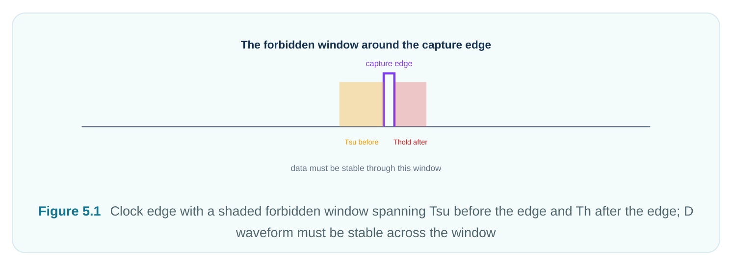
Together, setup and hold draw a forbidden window around the edge. D must not change inside [edge − Tsu, edge + Th] . Why does this window exist? Think of it like taking a photo. The shutter needs the scene to hold still for a moment, both just before and just after the click. A flip-flop is built from two latches with feedback. The input must be present and steady long enough for the inner circuit to lock in the value. Arrive too late and the value has not settled when the latch closes. That is a setup violation. Arrive too early with the next value and the latch grabs the wrong data. That is a hold violation. In the worst case the cell goes metastable. Metastability means the output floats between 0 and 1 for an unknown time before settling at random. The forbidden window exists to prevent exactly this. So setup and hold are not random library numbers. They are the timing form of a real settling need. Note that Tsu and Th are measured per cell and per corner. They also depend on how fast the clock and data signals ramp (their slew). We treat them as fixed numbers per corner to keep things simple.
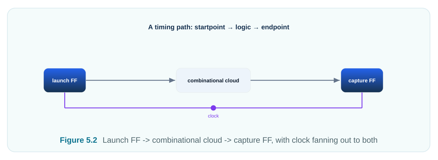
Every path we care about runs between two registers. The launch register sends the data on its clock edge. The capture register grabs it on its clock edge. Between them sits logic with some delay. STA does not run test patterns. Instead it computes the worst-case and best-case arrival of data at the capture D pin. It then compares those times against what the capture edge demands.
Setup Check Derivation
The setup check asks one thing. Does data arrive early enough? Data leaves at the launch edge. It passes through clock-to-Q and the logic. It must settle at the capture D pin before the capture edge, minus the setup time.
Let the clock period be T . The launch edge happens at time 0 . In a simple single-cycle path the capture edge happens one period later, at T . The latest the data can arrive is the data arrival time:
Arrival = Tlaunch_clk + Tcq + Tlogic_maxHere Tlaunch_clk is the clock delay to the launch register. Tcq is its clock-to-Q. Tlogic_max is the maximum logic delay. We use max for setup because slow data is the threat. The latest the data is allowed to arrive is the data required time:
Required = T + Tcapture_clk − TsuTcapture_clk is the clock delay to the capture register. We subtract Tsu because the data must be quiet during the setup window. The check is simple:
Arrival <= RequiredSetup slack is the margin by which we pass:
Setup slack = Required − Arrival
= (T + Tcapture_clk − Tsu) − (Tlaunch_clk + Tcq + Tlogic_max)
Define clock skew as Tskew = Tcapture_clk − Tlaunch_clk . Skew is positive when the capture clock arrives later. Then:
Setup slack = T + Tskew − Tsu − Tcq − Tlogic_maxPositive slack means the path passes. Negative slack is a violation. Notice that T has a + sign. More period gives more setup slack. That one fact drives the whole setup story. One more detail matters. Real designs also add clock uncertainty to the required time. Uncertainty bundles jitter (small cycle-to-cycle clock wobble) with a safety margin for effects not yet modeled. For setup, uncertainty is subtracted from the required time. This makes the check tighter:
Required = T + Tcapture_clk − Tsu − Uncertainty_setupSo the real setup slack is T + Tskew − Tsu − Tcq − Tlogic_max − Uncertainty_setup . When you debug, check the uncertainty term early. A setting that is too conservative can invent violations that do not exist in silicon.
Hold Check Derivation
The hold check asks a different question. Does data arrive too soon? This is a race. When the launch edge fires, the new data starts moving at once. If the logic is very fast and the capture clock is
a bit late, that fresh data could reach the capture D pin too early. It could overwrite the value the capture register was meant to grab on the same edge. Here is the key. The hold check uses the same edge for both launch and capture. It does not use the next-period edge. Both edges sit at time 0 . The earliest data can arrive uses minimum delays, because fast data is the threat:
Arrival = Tlaunch_clk + Tcq_min + Tlogic_minThe data must stay steady through the hold window. So the earliest it is allowed to change is:
Required = Tcapture_clk + ThThe check is:
Arrival >= RequiredHold slack is:
Hold slack = Arrival − Required
= (Tlaunch_clk + Tcq_min + Tlogic_min) − (Tcapture_clk + Th)
= Tcq_min + Tlogic_min − Tskew − Th
Like setup, real tools add clock uncertainty. But for hold the uncertainty is added to the required time. It tightens the check from the other side:
Required = Tcapture_clk + Th + Uncertainty_holdHold uncertainty is usually smaller than setup uncertainty. The same-edge race does not collect jitter over a full period. Both edges come from one clock event. Most of the jitter is shared by launch and capture, so it cancels. Now look at what is missing from hold slack. There is no T . Hold does not depend on the period. The race is on the same edge, so the period cancels out. This is the most important contrast in the chapter. It is also a near-certain interview question. Think of it this way. Hold protects a register from itself and its neighbor on the same beat. It does not matter how long until the next beat. It only matters whether the just-launched value can sneak across before the current sample locks in.
Setup (next edge) vs hold (same edge)
| Setup check | Hold check | |
|---|---|---|
| launch | capture (T) | same edge |
| data must arrive before T −Tsu | data must NOT arrive before Thold |
Figure 5.3 Same clock edge at t=0; fast data path racing to capture D, must arrive after edge+Th
Why Setup Scales With Frequency but Hold Does Not
Run the chip faster and T shrinks. Setup slack has +T , so a smaller period eats your setup margin directly. At some speed the slowest path's setup slack goes negative. That speed is your maximum operating frequency (Fmax). So setup is a frequency-limiting check. You fix setup failures at the architecture or speed level. Shorten the logic, add pipeline stages, use faster cells, or just slow the clock. Hold slack has no T term. So changing the clock speed does nothing for a hold violation. Run the chip at 1 Hz and a hold-failing path still fails. The new data still races through on the same edge. You fix hold through min path delay, hold time, and clock skew. None of these care how long you wait between edges. So you fix hold by slowing the data down. Insert buffers or delay cells on the fast path, or manage the skew. Never fix hold by changing frequency. The two tables below make the contrast clear.
| Aspect | Setup Check | Hold Check |
|---|---|---|
| Question | Is data early enough? | Is data too early? |
| Delay used for | Maximum (slow logic) | Minimum (fast logic) |
data
| Capture edge | Next edge (period T later) | Same edge as launch |
|---|---|---|
| Slack formula | T + Tskew − Tsu − Tcq − Tlogic_max | Tcq_min + Tlogic_min − Tskew − Th |
| Depends on T ? | Yes (scales with frequency) | No (period-independent) |
| Typical fix | Faster logic, pipeline, lower freq | Add delay on data, manage skew |
| Slack | Helped by | Hurt by |
| Setup | Larger T , positive skew, smaller Tsu / Tcq , faster logic | High frequency, large Tlogic_max , negative skew |
| Hold | Larger Tlogic_min , negative skew, smaller Th | Positive skew, very fast logic, large Th |
The Setup/Hold Trade-Off and the Role of Clock Skew
Now put setup and hold side by side. Watch the role of skew ( Tskew = Tcapture_clk − Tlaunch_clk ):
- In setup slack,
+Tskewappears. Making the capture clock arrive later (positive skew) helps setup. The data gets extra time before it is sampled. - In hold slack,
−Tskewappears. That same positive skew hurts hold. Delaying capture gives the racing new data more time to corrupt the sample. This is the core tension. Skew is not "good" or "bad" on its own. It trades one check against the other. Useful skew is a deliberate trick. You delay a capture clock on purpose to borrow time for a setup- critical path. But you must always confirm hold still passes on every path sharing that clock. Push skew too far either way and you just turn a setup problem into a hold problem, or the reverse. Skew direction Effect on setup Effect on hold Positive (capture later) Improves Degrades Negative (capture earlier) Degrades Improves Zero (balanced tree) Neutral baseline Neutral baseline Clock skew: helps one check, hurts the other −skew: hold easier / setup harder +skew: setup easier / hold harder zero skew Figure 5.4 Number line of skew; arrow toward +skew labeled "setup easier / hold harder", arrow toward −skew labeled "hold easier / setup harder"
Multicycle Context: Same-Edge vs Next-Edge Capture
Everything above assumed a single-cycle path. Launch at edge n , capture at edge n+1 . Some paths are given more time on purpose. A slow math block might be told "you have two cycles to compute." This is a multicycle path (MCP), a path allowed more than one cycle. We preview it here and cover it fully later. For a setup multicycle of N , the capture edge moves out to N·T . So the setup required time becomes about N·T + Tcapture_clk − Tsu . That is much more relaxed. But here is the trap. Relaxing setup by N cycles does not move the hold check on its own. By default, tools tie hold to the edge one cycle before the relaxed setup capture edge. That can push hold to a non-zero edge and create fake hold violations. To constrain a multicycle path right, set both the setup multiplier and a matching hold multiplier. That returns the hold check to the same-edge relationship.
The interview takeaway is this. Setup and hold are checked between a specific launch edge and a specific capture edge. Changing the setup relationship without fixing the matching hold edge is one of the most common constraint bugs. The tool always picks the most pessimistic edge pair for each check. The only exception is when a constraint like a multicycle or false path overrides that default.
Single-Corner vs Multi-Corner Reality
One more layer separates textbook math from sign-off. Setup is worst in the slow corner. That means high temperature (or low temperature on some nodes, due to temperature inversion), low voltage, and slow process. That is where logic is slowest and Tlogic_max is largest. Hold is usually worst in the fast corner. That means low temperature, high voltage, and fast process. That is where the racing data is quickest and Tlogic_min is smallest. A solid flow checks setup across all slow corners and hold across all fast corners at once. This is called multi-corner multi-mode (MCMM) analysis. The single-corner numbers here teach the mechanics. Sign-off repeats the same math across every corner that matters.
Worked Numeric Example
Let us put real numbers on both checks. Assume a single-cycle path with:
- Clock period
T = 2.50 ns(400 MHz) - Launch clock latency
Tlaunch_clk = 0.40 ns - Capture clock latency
Tcapture_clk = 0.60 ns→ skewTskew = +0.20 ns - Clock-to-Q:
Tcq_max = 0.22 ns,Tcq_min = 0.12 ns - Combinational logic:
Tlogic_max = 1.50 ns,Tlogic_min = 0.30 ns - Capture register
Tsu = 0.15 ns,Th = 0.10 ns
Setup check.
Arrival  = 0.40 + 0.22 + 1.50 = 2.12 ns
Required = 2.50 + 0.60 − 0.15 = 2.95 ns
Setup slack = 2.95 − 2.12 = +0.83 ns   (PASS)
Cross-check with the compact formula: Setup slack = T + Tskew − Tsu − Tcq_max − Tlogic_max = 2.50 + 0.20 − 0.15 − 0.22 − 1.50 = +0.83 ns . Consistent. Hold check. Same edge for launch and capture:
Arrival  = 0.40 + 0.12 + 0.30 = 0.82 ns
Required = 0.60 + 0.10        = 0.70 ns
Hold slack = 0.82 − 0.70 = +0.12 ns   (PASS)
Compact formula: Hold slack = Tcq_min + Tlogic_min − Tskew − Th = 0.12 + 0.30 − 0.20 − 0.10 = +0.12 ns . Consistent. Now show the period independence. Drop the frequency to 200 MHz ( T = 5.00 ns ):
Setup slack = 5.00 + 0.20 − 0.15 − 0.22 − 1.50 = +3.33 ns   (much healthier)
Hold slack  = 0.12 + 0.30 − 0.20 − 0.10        = +0.12 ns   (UNCHANGED)
Setup margin jumped a lot. Hold did not move. That single comparison is the cleanest proof. Frequency tuning rescues setup and does nothing for hold. Finally, show how skew bites hold. Suppose place-and-route pushes capture latency to 0.72 ns ( Tskew = +0.32 ns ) with the same fast logic:
Hold slack = 0.12 + 0.30 − 0.32 − 0.10 = 0.00 ns (right on the edge)A little more positive skew and this path tips into a hold violation. And this happens even though setup got easier.
Reporting Setup and Hold Checks
In practice you ask the tool to report the worst paths for each check. Then you read the slack at the bottom of the report. The constraint that defines the clock and the timing windows is standard SDC. The report commands and switches vary by tool, so they are flagged as illustrative.
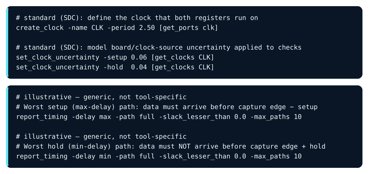
When you read the output, confirm three things on every critical path. First, the launch and capture clock edges the tool used. That is same-edge for hold and next-edge for single-cycle setup. Second, which delay corner was applied, max or min. Third, the endpoint slack with its sign. A negative number is a violation. Its size tells you how much delay you must remove for setup or add for hold.
Interview Q&A
arrives at the capture D pin at Tlaunch_clk + Tcq + Tlogic_max . We use max delay because slow data threatens setup. It must arrive before the next capture edge minus setup, which is T +
Tcapture_clk − Tsu . Slack is required minus arrival. This simplifies to T + Tskew − Tsu − Tcq − Tlogic_max , where Tskew = Tcapture_clk − Tlaunch_clk . The +T term is the headline. Setup margin grows with the clock period.
against the same clock edge that launched the data, not the next-period edge. Both edges sit at the same instant. So when you form required − arrival the period cancels. Concretely, hold slack is Tcq_min + Tlogic_min − Tskew − Th , which has no T . That is why slowing the clock fixes setup but never fixes hold.
lower the frequency. Hold is period-independent, so that wastes time. Fix it by slowing the data. Insert buffers or delay cells on the short min-delay path to raise Tlogic_min . Or rebalance the clock tree to cut the positive skew that hurts hold. Always re-run the setup check afterward. Added data delay and skew changes can erode setup margin elsewhere.
skew (capture clock later than launch) adds time before sampling. So it helps setup ( +Tskew ) but hurts hold ( −Tskew ), because the racing new data gets more time to corrupt the sample. Useful skew is the deliberate trick of delaying a capture clock to borrow margin for a setup-critical path. It is valid only after you verify that every hold path on that clock still passes. Overdoing it just turns a setup problem into a hold problem.
Key Takeaways
- Every timing path runs from a launch register through logic to a capture register. We model it with
Tcq,Tsu, andTh. - Setup asks "is data early enough?" It uses max delay against the next edge:
slack = T + Tskew− Tsu − Tcq − Tlogic_max. It scales with frequency and sets Fmax. - Hold asks "is data too early?" It uses min delay against the same edge:
slack = Tcq_min +Tlogic_min − Tskew − Th. It is period-independent. - Clock skew trades the two checks against each other. Positive skew helps setup and hurts hold. Negative skew does the reverse.
- Fix setup with faster logic, pipelining, or a slower clock. Fix hold by adding data delay or rebalancing skew. Never fix hold by changing frequency.
- Always read which edges and which delay corner a report used. Multicycle constraints must set both setup and hold multipliers, or they create false hold violations.
Comments
Leave a Reply