 ChipBuddy
← Home
ChipBuddy
← Home
Constraining a Design (the SDC Contract)
Static Timing Analysis (STA, the math that checks if signals arrive on time) is powerful but very literal. It does not know what you meant. It only knows what you told it. The tool checks every path you point it at. It skips every path you tell it to skip. It runs the design at whatever speed you set. If you set nothing, it assumes nothing. And "nothing" is risky. A path with no clock and no budget often shows no violation at all. The report can look all green while the chip fails in the lab. This is why constraints exist. A constraint file is written in SDC (Synopsys Design Constraints, a standard timing language built on Tcl). Think of it as a contract between you and the tool. It states how fast the clocks run. It states how much of each clock period the outside world uses. It states what the pins drive and are driven by. It also lists paths that are not real and should be skipped. Get the contract right, and STA predicts silicon well. Get it wrong, and STA just creates false confidence. This chapter builds the core constraint set step by step. It focuses on the part engineers get wrong most: budgeting timing at the block boundary (the edge of your chip block).
Why Constraints Are the Foundation of Trustworthy STA
Recall the basic timing check. It compares launch edge plus data-path delay against capture edge plus required time. Three of those four numbers come straight from constraints.
- The clock definition sets the launch and capture edges. It also sets the period between them.
- The boundary delays (input and output delay) set how much period is used off-chip. What is left is the on-chip budget.
- The port environment (driver, transition, load) makes port-path delays realistic, not idealized. Only the internal data-path delay comes from the netlist (your gate-level circuit) and the libraries. Everything else around that delay is something you assert. That gap is why constraint quality drives STA quality.
The Core Constraint Set
A few families of commands cover most of a clean block-level constraint file.
| Command | Purpose | Setup / Hold relevance |
|---|---|---|
| create_clock | Define a real clock: source pin, period, waveform | Both — sets launch/capture edges for every check |
| create_generated_clock | Derive a clock from another (divider, gate, MUX) | Both — keeps divided/derived domains coherent |
| set_input_delay | Time data arrives at an input port, | -max -> setup; -min -> hold |
relative to a clock
set_output_delay Time data is required at the receiver, -max -> setup; -min -> holdrelative to a clock
set_driving_cell Model the external gate driving an Both — sets realistic input| input port | transition | |
|---|---|---|
| set_load | Model the capacitance an output port | Both — sets realistic output-path |
| must drive | delay | |
| set_clock_uncertainty | Reserve margin for jitter/skew (and as | Both — tightens required time |
setup guard) All seven belong to the SDC standard. The first thing every contract needs is its clocks.
# standard (SDC)
# A 1.00 ns period (1 GHz) clock on the primary clock port.
create_clock -name clk_core -period 1.00 [get_ports clk]
# A generated clock: divide-by-2 off the core clock, defined on a flop's Q pin.
create_generated_clock -name clk_div2 \
-source [get_ports clk] -divide_by 2 \
[get_pins u_div/Q]
Now the tool knows the clocks. It can place edges. But for a path that crosses the block boundary, it still does not know what happens on the other side of the port. Boundary delays supply that.
Input and Output Delay: Carving Up the Period
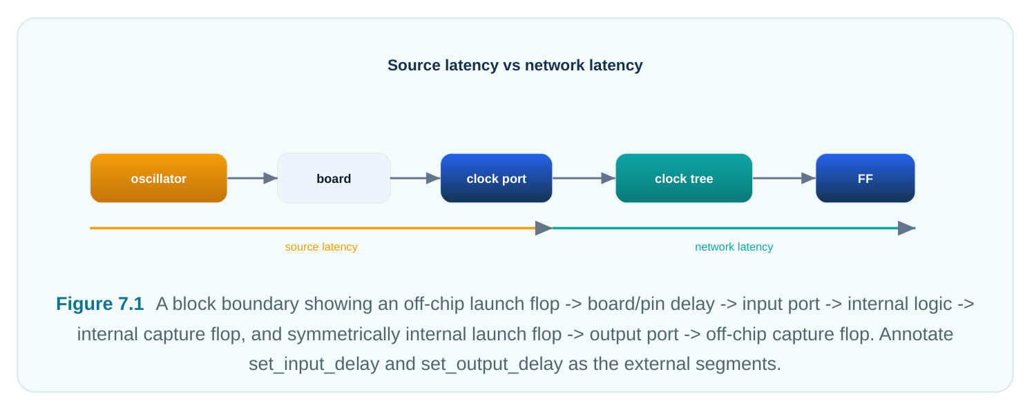
Here is the core idea of boundary budgeting. A register-to-register path that crosses a chip boundary still has exactly one clock period to finish. Part of that path lives outside your block. Part lives inside. The boundary delay tells STA how much period the outside part uses. Then the tool knows how much is left for the inside part.
set_input_delay answers one question. "Relative to its clock edge, how late does data reach thisinput port?" Suppose an upstream flop launches at the edge. The signal runs through its clock-to-Q and some board routing. It lands at your port 0.45 ns into the period. Then set_input_delay 0.45 tells STA the inside logic has only period − 0.45 (minus setup and uncertainty) to work.
set_output_delay answers the mirror question. "Relative to its clock edge, how early must data bevalid at this output port?" Suppose the outside receiver needs data 0.40 ns before its edge (its setup plus routing). Then set_output_delay 0.40 reserves that slice. That leaves period − 0.40 for the inside path from launch flop to port. A simple way to picture it. Input delay is time already spent before data reaches you. Output delay is time you must leave behind for the world after you.
# standard (SDC)
# Inputs are valid 0.45 ns after clk_core's edge (max -> setup budget),
# and remain stable until 0.12 ns after the edge (min -> hold budget).
set_input_delay -clock clk_core -max 0.45 [get_ports data_in[*]]
set_input_delay -clock clk_core -min 0.12 [get_ports data_in[*]]
# Outputs must be valid 0.40 ns before the downstream clk edge (max -> setup),
# and must not change before 0.08 ns after it (min -> hold).
set_output_delay -clock clk_core -max 0.40 [get_ports data_out[*]]
set_output_delay -clock clk_core -min 0.08 [get_ports data_out[*]]
MAX FOR SETUP, MIN FOR HOLD
The -max / -min split matches the two timing checks exactly.
| Check | Port | Delay used | Why |
|---|---|---|---|
| Setup | input | set_input_delay -max (input) | Worst case: data arrives as late as possible, leaving least internal time |
| Hold (input) | input | set_input_delay -min | Best case: data arrives as early as possible, risking a |
too-fast capture
| Setup | output | set_output_delay - | Receiver needs the most lead time before its edge |
|---|---|---|---|
| (output) | max | ||
| Hold | output (output) | set_output_delay - min | Receiver's hold window after its edge must be respected |
The -max numbers describe the slow, late corner of the outside world. That is worst for setup. The - min numbers describe the fast, early corner. That is worst for hold. Giving both halves makes boundary checks complete in both directions. Giving only -max is a classic cause of missed I/O hold violations.
Modeling the Port Environment Realistically
Boundary delay tells STA when signals cross the port. It says nothing about how steeply an input rises. It says nothing about how heavy an output's load is. Yet both strongly affect the first or last gate inside the block. Left at defaults, an input port acts like an ideal, infinitely sharp source. An output acts like it drives nothing. Both are too optimistic. Both distort port-path slack (the timing margin on a path). Two commands fix this.
set_driving_cell tells STA a real library gate of a given strength drives the input port. The tool thencomputes a realistic input slew (how fast the edge rises or falls). It uses that gate's drive resistance against the on-chip net, just like an internal net. A weak driver gives a slow input edge. That slows the first internal gate. This captures reality instead of hiding it.
set_load tells STA how much capacitance the output port must charge. That includes the bond pad,package, board trace, and far-end pin. A larger load means a slower last gate. That eats into the output path's budget.
# standard (SDC)
# An external mid-strength inverter drives the inputs; STA derives input slew from
it.
set_driving_cell -lib_cell INVX4 -pin Z [get_ports data_in[*]]
# Outputs must drive 0.04 pF of external capacitance.
set_load 0.04 [get_ports data_out[*]]
Without set_driving_cell , you have two other options. You can let the tool assume an ideal source, which is too optimistic. Or you can assert an input transition directly with set_input_transition . The driving-cell form is usually better. It stays self-consistent across corners. It scales with the library data. A fixed number you set by hand does not.
Virtual Clocks for Off-Chip-Referenced I/O
Here is a subtle but common case. The flops on the other side of a port use a clock that does not exist inside your block. The board clock, or a divided clock made elsewhere, never enters your netlist. But your input and output delays must still point to it. That is the edge the outside logic really uses. The fix is a virtual clock (a clock with no source pin). It has a period and waveform but attaches to nothing. You point your boundary delays at it. Then the link between the outside edge and your inside edge is modeled right, including any phase shift.
# standard (SDC)
# A virtual clock representing the off-chip clock the I/O is referenced to.
create_clock -name clk_io_virt -period 1.00
# Boundary delays now reference the virtual edge, not the internal clock.
set_input_delay  -clock clk_io_virt -max 0.45 [get_ports data_in[*]]
set_output_delay -clock clk_io_virt -max 0.40 [get_ports data_out[*]]
Virtual clocks also let you say something useful. The outside world and the inside core share a frequency but not the same physical clock tree. This keeps boundary checks honest about skew between the two domains.
Constraint Completeness, and the Two Ways to Be Wrong
There are exactly two failure modes for a constraint file. They are mirror images. Under-constraining (unconstrained paths). A path with no clock relationship is often not checked at all. A port with no delay may be checked against a zero budget that always passes. These show up as "no path" or as huge positive slack. They are silent killers. The tool reports clean. The silicon fails.
Every real flow should run a completeness audit. It should find unclocked registers, unconstrained ports, and ports with no I/O delay. Treat that list as a blocking checklist, not a curiosity. Over-constraining (falsely constrained paths). This is the opposite error. You assert a relationship that is tighter or different from reality. An example: leaving a set_input_delay at an inflated value copied from another block. Another: failing to mark a truly asynchronous crossing as a false path, so the tool times a path that can never carry a clean value. Over-constraining makes violations that are not real. Engineers then chase phantom problems. It inflates effort and area. The discipline is the same both ways. Every register must have a clock. Every port must have a delay, or a justified exception. Every exception must have a stated reason.
| Mistake | Symptom in reports | Consequence |
|---|---|---|
| Input/output delay only -max , no - | Hold checks pass too easily at | Undetected I/O hold failures in |
| min | ports | silicon |
| Forgotten create_clock on a clock | Registers show "unclocked", port | Entire domain unanalyzed huge slack |
| No set_driving_cell / | Port-path slew/delay idealized set_load | Optimistic port slack; missed violations |
| Wrong reference clock on I/O delay | Plausible but incorrect boundary slack | Budget mis-carved; marginal at speed |
| Async crossing not declared false/ | Spurious cross-domain | Wasted effort, pessimistic |
| multicycle | violations | closure |
A Small but Complete Worked Example
Consider a block dma_engine . It has one 1 GHz functional clock on port clk . It has a status output irq tied to the same off-chip clock. It has a data bus in and out. It also has an async reset rst_n that should not be timed. Here is a compact, self-consistent contract.
# standard (SDC)
# ---- Units assumed: ns / pF as per the library ----
# 1. Real clock on the clock port: 1 GHz, 50% duty.
create_clock -name clk_core -period 1.00 [get_ports clk]
# 2. Uncertainty: reserve margin for jitter + estimated skew before CTS.
set_clock_uncertainty -setup 0.08 [get_clocks clk_core]
set_clock_uncertainty -hold  0.04 [get_clocks clk_core]
# 3. Input boundary budget (both directions).
set_input_delay -clock clk_core -max 0.45 [get_ports {data_in[*] cmd[*]}]
set_input_delay -clock clk_core -min 0.12 [get_ports {data_in[*] cmd[*]}]
# 4. Output boundary budget (both directions).
set_output_delay -clock clk_core -max 0.40 [get_ports {data_out[*] irq}]
set_output_delay -clock clk_core -min 0.08 [get_ports {data_out[*] irq}]
# 5. Realistic port environment.
set_driving_cell -lib_cell INVX4 -pin Z [get_ports {data_in[*] cmd[*]}]
set_load 0.04 [get_ports {data_out[*] irq}]
# 6. Exclude the asynchronous reset from timing (illustrative
#    -- generic intent, exact exception command is tool-specific).
# set_false_path -from [get_ports rst_n]
Read top to bottom, this file tells the whole story. It gives the clock and its margin. It gives how much period the outside world uses at each port, for both setup and hold. It gives what drives and loads those ports. It names the input that is not timed on purpose. Hand an engineer just this file and the netlist. They could rebuild the timing closure context exactly. That is the test of a good contract. The one place to slow down is step 6. Exception commands like false-path and multicycle-path belong to SDC. But their exact option syntax varies. So does the way an engine resolves overlapping exceptions. Treat the exact wording as tool-specific. Verify it against your flow's docs. The intent is universal: "do not time the reset deassertion as a synchronous path." The exact command line is the part to confirm.
Interview Q&A
data is valid at the input port 0.45 ns into the period, relative to the clock edge. So 0.45 ns of the period was already used off-chip. That is the upstream clock-to-Q plus board routing. It reserves that 0.45 ns from the internal setup budget. The logic from port to capture flop now has only period − 0.45 − setup − uncertainty of room. The -max form drives setup. You would also give -min for the hold side.
ties the input slew to a real library gate's drive behavior. So it scales correctly across PVT corners
during multi-corner analysis. A hand-entered transition is one fixed number. It may be right at one corner and wrong at others. You must also maintain it by hand. The driving-cell form stays consistent with how the rest of the design is characterized. That makes port-path delays more trustworthy.
port use a clock that never enters your block. That could be a board clock or an externally divided clock. You make a sourceless clock with the right period and waveform. You point your input and output delays at it. Then the outside-to-inside edge relationship is modeled right. That includes any phase offset and the fact that the two clock trees can skew on their own.
problems would you suspect first? Under-constraint. I would audit for unclocked registers. A missing create_clock leaves a whole domain unanalyzed. I would check for ports with no input/ output delay, since their boundary paths get a near-zero budget. I would check for I/O delays given only in -max , which hides hold issues. I would also check async crossings that should be exceptions but instead pass silently or get over-constrained. Green reports on an incomplete contract mean the tool checked the wrong thing, or nothing.
Key Takeaways
- Constraints are a literal contract: STA is exactly as correct as the clocks, boundary budgets, and exceptions you declare — no more.
create_clockplaces the edges;set_input_delay/set_output_delaycarve the single available period between off-chip and on-chip logic.-maxfeeds setup (late/slow external world),-minfeeds hold (early/fast external world); supply both at every port.set_driving_cellandset_loadmake port paths physically accurate by modeling real input slew and real output capacitance.- Use a virtual clock when I/O is referenced to a clock that never enters your block.
- The two failure modes are under-constraining (silent, dangerous, green reports over real failures) and over-constraining (phantom violations); audit completeness and justify every exception.
Comments
Leave a Reply