 ChipBuddy
← Home
ChipBuddy
← Home
Operating Conditions, PVT Corners & Derating
Chapter 9 — Operating Conditions, PVT Corners & Derating
So far we treated each gate as having one fixed delay. Real silicon does not work that way. The same buffer might pass an edge in 35 ps on a fast, cold chip. The same buffer might take 110 ps on a slow chip that is hot with a weak supply. Suppose you sign off at one condition. Suppose the part ships into a different one. Then your margin disappears and the chip fails in the field. This chapter shows how STA handles this. We analyze across Process, Voltage, and Temperature (PVT) corners. A corner is one named combination of those three. We pair each corner with the right wire data. We add derating (a simple safety multiplier) on top.
Why One Analysis Point Is Not Enough
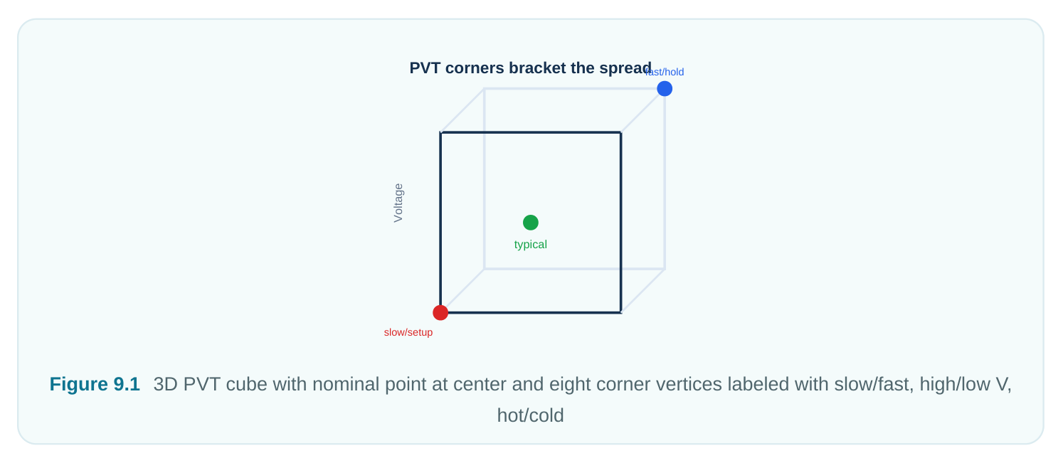
Chip making is a statistical process. No two chips are identical. Across a batch, transistor strength, channel size, and metal width all vary. So nominal delay is not a single value. It is the center of a distribution (a spread of possible delays for the same netlist). Think of it like a bell curve. Two more things ride on top of process:
- Voltage changes with supply droop and regulator tolerance. Lower supply means weaker drive. Weaker drive means slower edges.
- Temperature changes with the surroundings and self-heating. Its effect on delay is not always one- directional, as we will see. A single nominal run checks just one point in this 3D space. Real chips live all over it. STA must bound the whole spread. We do that with corners.
The Corner Concept
A corner is a named mix of one process, one voltage, and one temperature. We do not simulate the full spread. Instead we pick extreme mixes that fence in the spread. If the design passes at the fence, it passes everywhere inside. It is like checking the coldest and hottest day of the year. Pass both and every day in between is safe.
| PVT Axis | Direction | Effect on Cell Delay | Intuition |
|---|---|---|---|
| Process | Slow (SS) | Larger | Weak transistors, high Vt, long channels |
| Process | Fast (FF) | Smaller | Strong transistors, low Vt |
| Voltage | Low | Larger | Less drive, slow charging of load |
| Voltage | High | Smaller | More drive current, faster edges |
| Temperature | Hot (classic) | Larger | Carriers slow down with heat |
| Temperature | Cold (classic) | Smaller | Carriers move faster, faster switching |
The process label names the NMOS/PMOS pair. SS means slow-slow. TT means typical-typical. FF means fast-fast. There are also skewed corners SF and FS. These stress one transistor type against the other. They matter for signal integrity and ratioed circuits.
Which Corners Hurt Setup vs Hold
The two timing checks fail under opposite conditions. So they need opposite corners.
A setup check fails when data arrives too late. Slow logic is the enemy here. That means slow process, low voltage, and (classically) hot temperature. So setup is usually signed off at slow / low- voltage / hot. A hold check fails when data arrives too early. Early data races ahead and overwrites the next stage before the clock catches it. Fast logic is the enemy here. That means fast process, high voltage, and cold temperature. So hold is usually signed off at fast / high-voltage / cold.
| Failing | Worst-Case Corner | ||
|---|---|---|---|
| Check | Why | ||
| Condition | (classic) | ||
| Setup | Data too late | Slow / Low-V / Hot | Maximizes data delay against the clock period |
| Hold | Data too early | Fast / High-V / Cold | Minimizes data delay against a short hold |
window
THE TEMPERATURE-INVERSION CAVEAT
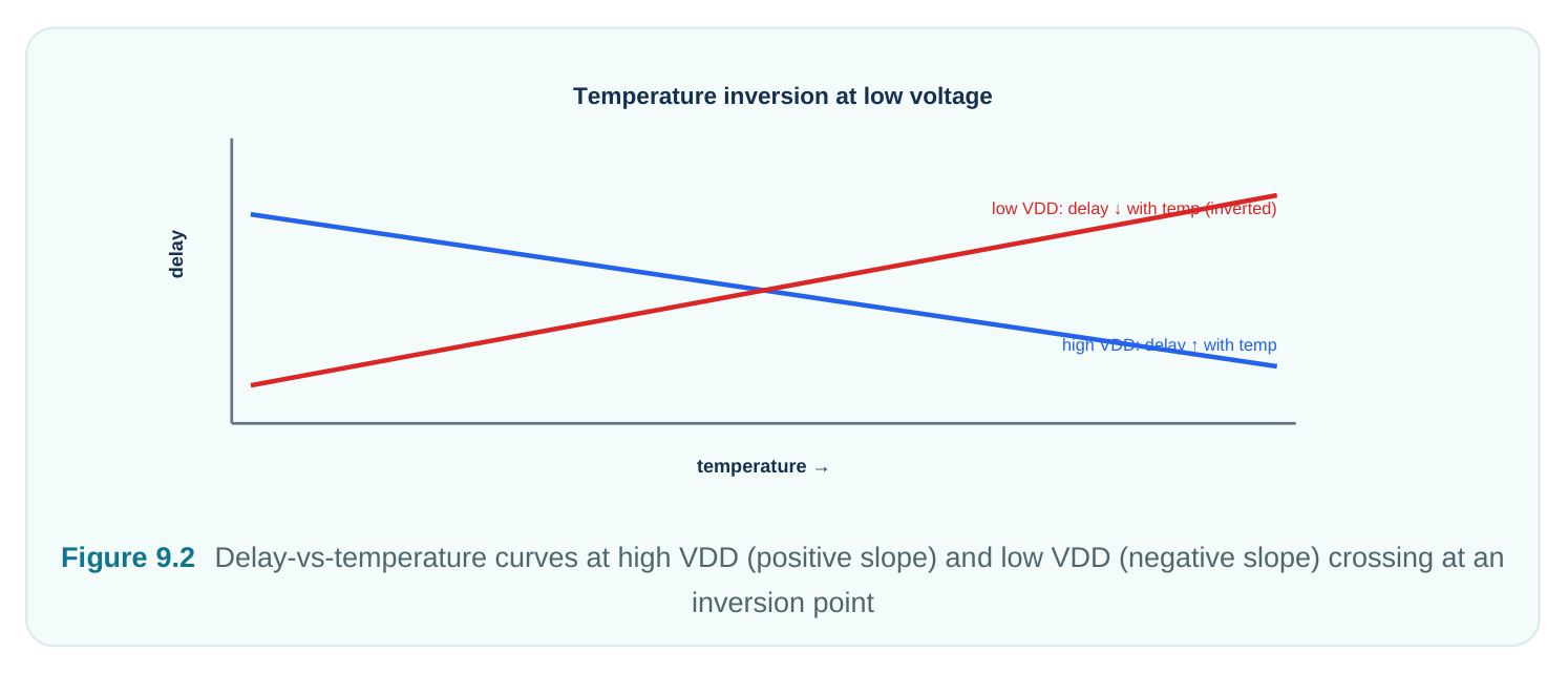
The "hot is always slow" rule holds at older, higher-voltage nodes. At modern low supplies, two physical effects fight, and they swap which one wins:
- Mobility drop with heat slows transistors. This is the classic effect.
- Threshold-voltage drop with heat speeds transistors. At high supply the mobility effect wins. So hot is slowest. At low supply the overdrive (Vgs − Vt) is small. So the Vt effect wins and cold becomes the slow corner. This is temperature inversion. The result is simple but important. You can no longer assume hot is worst for setup. At advanced nodes you must run both hot and cold for both checks. Let the tool find the true worst slack. Assuming the classic mapping at a low-voltage node is a common and dangerous mistake.
Library Characterization and Matching Parasitics
Each corner needs its own cell library. That library is built by SPICE simulation of every cell at that exact P, V, and T. A library built for SS/0.70V/125C reports delays valid only at that point. Using it anywhere else is meaningless. So a project signing off at four corners carries four or more libraries. Timing is only half the story. The interconnect (the wires) must match too. Parasitic extraction gives RC values. These also vary with manufacturing:
- Cmax / Rmax (often "RC-worst"): thick, wide metal with large coupling. This slows nets. It pairs with the setup corner.
- Cmin / Rmin (often "RC-best"): thin, narrow metal. This speeds nets. It pairs with the hold corner. The pairing must be physically consistent. A correct setup corner is slow cells plus slow wires. A correct hold corner is fast cells plus fast wires. Mixing a slow library with best-case RC under-counts delay. That gives optimistic, untrustworthy slack. Modern flows bundle these pairings as analysis views. A view is a named bundle of library set, RC corner, and constraints. The tool can then sweep all views in one session.
Derating: A Cheap Guardband
Corners bound the systematic spread. But two uncertainties still remain. One is variation within a single die (on-chip variation, OCV). The other is modeling error. Building more corners is expensive. So STA offers a blunt but useful tool: timing derate, a global multiplier added to delays as extra margin. The idea is simple. Take a computed path delay and scale it. A late derate of 1.08 says "assume this path could be 8% slower than the library claims." An early derate of 0.92 says "assume it could be 8% faster." Applied to the right paths, this adds pessimism without building new libraries.
| Concept | Multiplier | Applied To | Purpose |
|---|---|---|---|
| Late derate | > 1.0 (e.g. 1.08) | Data path (setup), clock launch | Make data arrive later → safe setup |
| Early derate | < 1.0 (e.g. 0.92) | Clock capture path (setup) | Make clock arrive earlier → safe setup |
| Late derate | > 1.0 | Capture clock path (hold) | Safe hold |
| Early derate | < 1.0 | Data path (hold), launch clock | Safe hold |
Here is the key subtlety for OCV. STA applies a late derate to the launch path. It applies an early derate to the capture path of a setup check. The reverse holds for hold. So a shared clock segment used by both paths gets derated in opposite directions. That double-counts pessimism on shared logic. Advanced OCV methods later fix this by crediting back the common path. Derating is therefore a rough first model of pessimism. It is simple, cheap, and on purpose conservative.
Why Sign-Off Demands Multiple Corners
It is tempting to run typical-typical only. It is fast and usually passes. But TT bounds nothing. Setup violations hide at the slow corner. Hold violations hide at the fast corner. A design clean at TT can fail both checks in silicon. So sign-off needs at least a setup-worst corner and a hold-worst corner. At advanced nodes it needs several of each. That means more voltages for DVFS modes, both temperatures for inversion, and more RC corners. Multi-corner multi-mode (MCMM) sign-off runs all relevant corner-by-mode combinations. It reports the worst slack per endpoint across the whole grid. Fixing the worst case fixes them all.
Worst-Case-Corner Selection: A Worked Example
Suppose a block runs at two supplies. One is a high-performance 0.95 V mode. One is a low-power 0.60 V mode. It runs across −40C to 125C. The process has three splits: SS, TT, FF. Naively that is 3 × 2 × 2 = 12 corners. We prune them with reasoning. For setup, we want maximum data delay. Process must be SS. Voltage must be the lower one, 0.60 V. Temperature is unclear because 0.60 V is near inversion. So we keep both 125C and −40C. That gives two setup corners: SS/0.60V/125C and SS/0.60V/-40C . For hold, we want minimum data delay. Process must be FF. Voltage must be the higher one, 0.95 V. At 0.95 V we are above inversion, so cold is fastest: FF/0.95V/-40C . To be safe against any leftover inversion margin, we may also keep FF/0.95V/125C .
| Selected Corner | Process | Voltage | Temp | Check Targeted |
|---|---|---|---|---|
| SS/0.60V/125C | Slow | 0.60 V | 125C | Setup |
| SS/0.60V/-40C | Slow | 0.60 V | −40C | Setup (inversion guard) |
| FF/0.95V/-40C | Fast | 0.95 V | −40C | Hold |
| FF/0.95V/125C | Fast | 0.95 V | 125C | Hold (inversion guard) |
We cut 12 candidates down to 4. We did this by asking which physical extreme each check fears. We kept both temperatures at the inversion-prone voltages instead of guessing. This is exactly the judgment an interviewer wants to see.
Commands
Set the operating condition. This points to a named condition defined in the loaded library:
# standard (SDC-adjacent): select a characterized operating condition
set_operating_conditions -library slow_lib "ss_0p60v_125c"
Apply timing derates for OCV-style pessimism:
# standard (SDC): derate the late/early data and clock paths
# late paths: assume up to +8% slower
set_timing_derate -late  -data  1.08
set_timing_derate -late  -clock 1.08
# early paths: assume up to -8% faster
set_timing_derate -early -data  0.92
set_timing_derate -early -clock 0.92
A driver that sweeps several corners and collects the worst slack. Note this is pseudo-code, not a vendor command set:
# illustrative — generic, not tool-specific
set corners {
{SS_060_125 slow_lib ss_0p60v_125c rc_max setup}
{SS_060_m40 slow_lib ss_0p60v_m40c rc_max setup}
{FF_095_m40 fast_lib ff_0p95v_m40c rc_min hold}
{FF_095_125 fast_lib ff_0p95v_125c rc_min hold}
}
foreach c $corners {
lassign $c name lib cond rc check
reset_design
set_operating_conditions -library $lib $cond
read_parasitics  $rc                          ;# illustrative
if {$check eq "hold"} {
set_timing_derate -early -data 0.92       ;# standard (SDC)
} else {
set_timing_derate -late  -data 1.08       ;# standard (SDC)
}
set slack [report_worst_slack -check $check]  ;# illustrative
puts "Corner $name ($check): worst slack = $slack"
}
Interview Q&A
temperature inversion. Heat lowers carrier mobility, which slows the cell. Heat also lowers threshold voltage, which speeds the cell. At high supply the mobility effect wins, so hot is slowest. At the low supplies in advanced nodes, overdrive is small. So the Vt effect wins and cold is slowest. You cannot assume hot is worst for setup. You run both temperatures and let the tool find the true minimum slack.
consistency. Setup fears maximum delay. So a slow cell library must pair with worst-case RC (Cmax/ Rmax) to slow the wires too. Hold fears minimum delay. So a fast library pairs with best-case RC (Cmin/Rmin). Mixing a slow library with best-case RC understates delay. That yields optimistic, invalid slack.
characterized analysis point. It has its own SPICE-accurate library and matched wires. So it models the systematic PVT spread precisely, but it is expensive to build. A derate is a global multiplier layered on existing delays. It adds margin cheaply for on-chip variation and modeling error. Corners bound the distribution. Derates pad against leftover uncertainty inside it.
handled? In a setup check the launch clock gets a late derate. The capture clock gets an early derate. Any clock segment shared by both paths is then derated in opposite directions at once. That is pure double-counted pessimism. One physical segment cannot be both slow and fast. Advanced OCV (CRPR, or common-path pessimism removal) computes the shared segment. It credits back the overpessimism and recovers false-failing slack.
Key Takeaways
- Delay is a distribution, not a number. It varies with Process, Voltage, and Temperature, and one nominal run bounds nothing.
- Corners fence in the spread. Setup is classically worst at slow / low-V / hot. Hold is worst at fast / high-V / cold.
- Temperature inversion at low supply can make cold the slow corner. Never assume hot is worst at advanced nodes. Run both temperatures.
- Each corner needs its own characterized library and a physically matched RC extraction. Use slow cells plus worst RC for setup, fast cells plus best RC for hold.
- Derating is a cheap multiplier guardband for on-chip variation and modeling error. It adds pessimism on purpose and is later refined by common-path pessimism removal.
- Sign-off is multi-corner, multi-mode. Verify every required corner, not just typical. Prune the corner list by asking which physical extreme each check fears.
Comments
Leave a Reply