 ChipBuddy
← Home
ChipBuddy
← Home
Asynchronous Crossings & Metastability
Chapter 18 — Asynchronous Crossings & Metastability (Deep
Dive)
Static timing analysis (STA, checking chip timing without test vectors) rests on one quiet assumption. It assumes every launch edge and every capture edge come from clocks with a fixed, known phase relationship. Phase relationship means how the two clock edges line up in time. When that holds, the tool knows exactly how much time sits between launch and capture. Then a setup/hold check makes sense. But some clock domains are truly asynchronous. They use different oscillators. They have no fixed ratio. Their phase drifts apart. For those, the assumption breaks. This chapter covers what STA can and cannot do at such boundaries. It covers the physics of metastability that makes them risky. It covers synchronizer circuits that tame them. It also covers the small, exact timing job STA still does there.
Why STA Cannot Time a True Asynchronous Crossing
Picture one register in clock domain A. It launches data. Another register in clock domain B captures it. A setup check asks one question. Does data reach the capture pin at least Tsetup (the setup time, the quiet time data needs before the edge) early? To answer, the tool needs the time from launch edge
to capture edge. For synchronous clocks it finds this from the shared edge. They share a frequency, an integer ratio, or a fixed offset. Asynchronous clocks have no shared edge. The two domains drift all the time. So over time, every phase relationship happens. The worst-case gap from launch to capture can get arbitrarily near zero. A setup check against a zero or negative window cannot be met. The tool would report huge violations. No buffering would fix them. The trouble is not delay. The trouble is that the receiving flop will, sooner or later, sample its D input mid-transition.
So the right response is not to fix the path delay. Instead, declare the path false for setup/hold. Then make sure the receiving logic is built to survive the bad sample that must come. That structure is a synchronizer. STA's leftover job is to constrain the synchronizer. Valid setup/
Crossing type Phase relationship STA action
Same clock Fixed (0 skew Yes Normal check
| Divided / multiplied, | Fixed integer ratio | Yes | Normal check (multi-cycle if |
|---|---|---|---|
| aligned | needed) | ||
| Phase-shifted, same | Fixed offset | Yes | Check with offset |
source
Truly asynchronous None (drifting) No False path + constrain
The Physics of Metastability
A flip-flop settles its output by regenerative feedback. It uses two cross-coupled inverters. Once nudged toward 0 or 1, they snap fully to that rail. This works because the circuit has two stable states. It also has one unstable middle point. That middle point is the metastable point. Think of a ball balanced on a thin ridge.
Say the D input is changing right at the sampling instant. Then the setup/hold window is broken. The master latch can grab a voltage near the ridge. The feedback still pushes away from the ridge. But the nearer the captured voltage is to the exact balance, the slower it rolls off. During that wait, output Q sits at an in-between level. It is neither a clean 1 nor a clean 0. One downstream gate may read it as
- 1. Its neighbor may read it as 0.
The voltage moves away from the metastable point exponentially. Its time constant is τ (tau, how fast the latch resolves). It is set by the gain and bandwidth of the latch transistors.
V_separation(t) ∝ exp(t / τ)The chance the device is still unresolved after a settling time ts drops exponentially. This gives the classic mean-time-between-failures idea:
MTBF ≈ exp(ts / τ) / (f_clk × f_data × T0)In plain words: more settling time ts makes failures exponentially rarer (the top). A faster receiving clock, faster async data, and a wider susceptibility window T0 make failures more common (the bottom). Two device parameters matter. τ says how fast it resolves. T0 says how often it enters metastability. Both come from the cell library for that flop. Two facts follow. First, metastability can be made vanishingly unlikely. It can never be made zero. The exponential never reaches infinity for finite ts . Second, the one lever you truly control is ts . That is the settling time you allow before the metastable node drives other gates. Every synchronizer uses this one idea.
Synchronizer Structures
A two-flop synchronizer puts two flip-flops in series in the receiving domain. There is no combinational logic between them.
The first flop (FF1) is the one that may go metastable. The full receive-clock period, minus a small margin, is then given to FF1 to settle before FF2 samples it. That period is the settling budget ts . By
the time FF2 captures, FF1 has almost surely reached a clean level. FF2 then passes a stable value into the logic. A three-flop synchronizer adds a third stage. This gives the metastable event up to two receive-clock periods to settle. That is the FF1→FF2 cycle plus one more cycle of headroom. MTBF depends exponentially on ts . So adding a stage multiplies MTBF a lot. The cost is one extra cycle of latency. The choice is an MTBF-versus-latency trade.
| Structure | Settling budget | Latency added | Typical use |
|---|---|---|---|
| 1-flop (none) | ~0 | 0 | Never for async data |
| 2-flop | ~1 dest period | 1–2 dest cycles | Standard control-bit CDC |
| 3-flop | ~2 dest periods | 2–3 dest cycles | High-frequency or high-reliability |
The settling budget is itself a timing number: ts ≈ T_dest − T_setup(FF2) − clock_uncertainty − (interconnect from FF1/Q to FF2/D) . Anything that lengthens that interconnect or adds setup at FF2 shrinks ts . And, exponentially, it shrinks your MTBF. That is exactly why STA must guard that one segment.
Handling CDC Paths in STA
The split of work is clean. CDC means clock domain crossing. STA does two things at an async boundary:
- 1. Remove the impossible check. Declare the launch-to-capture path across the boundary a false
path (or a clock-group exception). Then the tool stops reporting unfixable setup/hold violations.
- 2. Protect the settling budget. Put a tight max-delay on the FF1→FF2 segment. Then FF1's output
reaches FF2 with most of its resolution time intact. Declaring clocks asynchronous as a group is the cleaner, scalable way. It false-paths all crossings between two domains at once:
# standard (SDC)
# Tell STA these clocks have no phase relationship.
# This removes setup/hold checks on every path between them.
set_clock_groups -asynchronous \
-group {clk_dom_a} \
-group {clk_dom_b}
If you must handle one crossing instead of a whole domain, a targeted false path works. But it is errorprone at scale:
# standard (SDC)
# Point exception on one crossing (use sparingly; prefer clock groups)
set_false_path -from [get_pins src_reg/CK] \
-to   [get_pins sync_ff1/D]
Now the part many engineers forget. False-pathing the crossing does not leave the synchronizer unconstrained. The FF1→FF2 segment sits fully inside the destination domain. It is a synchronous path. So it must be timed normally for the settling budget to be real. On top of the normal check, teams often add a max-delay. This stops routing or logic from stealing settling time:
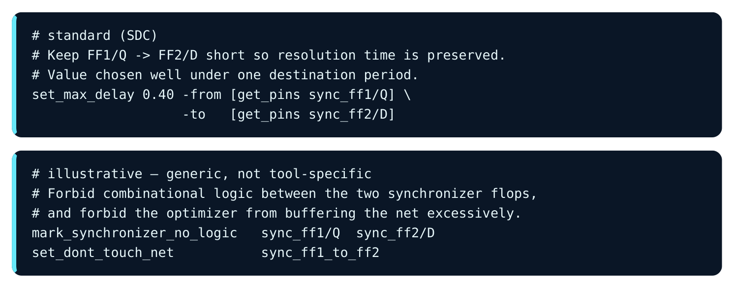
A fine point about hold. FF1→FF2 is intra-domain. So hold still applies and must pass. The false path only killed the cross-domain setup/hold that had no meaning. Forgetting this, and false-pathing the internal segment too, is a classic way to ship a broken synchronizer that STA calls clean.
Multi-Bit CDC Hazards and Data Coherency
A two-flop synchronizer protects one bit. Putting one per bit on a bus is a coherency trap. Each bit's metastable resolution is its own coin flip. Say several bits change in the same source cycle. The destination may catch some new bit values and some old bit values in one capture cycle. They resolved on different sides of the boundary. So the bus briefly holds a value that was never sent.
WORKED EXAMPLE — WHY PER-BIT SYNCHRONIZERS CORRUPT A BUS
A 4-bit counter crosses from domain A to domain B. It increments 0111 → 1000. Four bits flip at once. Suppose bit b3's synchronizer resolves to the new value. Suppose b2, b1, and b0 resolve to old values for one cycle:
| Bit | Old | New | Resolved this cycle | Destination sees |
|---|---|---|---|---|
| b3 | 0 | 1 | new (1) | 1 |
| b2 | 1 | 0 | old (1) | 1 |
| b1 | 1 | 0 | old (1) | 1 |
| b0 | 1 | 0 | old (1) | 1 |
The destination reads 1111 (decimal 15). The counter never held 15, which sits far past both 7 and 8. A control FSM acting on 15 could take a wholly wrong branch. The fixes target coherency, not metastability:
- Gray coding. Encode the bus so only one bit changes per increment. Now at most one synchronizer is mid-resolution. So the destination gets either the old code or the new code. Both are legal, adjacent values. This is ideal for counters and pointers (FIFOs).
- Handshake. The source asserts a request. It waits for an acknowledge synchronized back. Data sits stable on a parallel bus while one synchronized control bit signals validity. That parallel bus need not be synchronized bit by bit. This gives low throughput, full coherency, any data.
- Asynchronous FIFO. A dual-port memory with Gray-coded read/write pointers synchronized across the boundary. This gives high throughput. It decouples rates. It is the workhorse for streaming data. Method Coherent multi-bit? Throughput Latency Typical use Per-bit 2-FF No High Low Independent control bits only Gray code Yes (monotonic) High Low Counters, FIFO pointers Handshake Yes Low High Occasional config words Async FIFO Yes High Moderate Data streams across rate boundaries The takeaway: never send a raw multi-bit bus through parallel single-bit synchronizers.
Reset Domain Crossing and Recovery/Removal
Asynchronous resets make their own crossing problem. An async reset asserts at once, with no clock needed. That is its purpose, and it is safe. The danger is deassertion. When reset releases, the flop must leave reset cleanly relative to the clock edge. Otherwise it can itself go metastable. STA checks deassertion with two timing arcs. They mirror setup and hold:
- Recovery — reset must deassert at least
T_recoverybefore the active clock edge. This is the setup-like check. - Removal — reset must stay asserted at least
T_removalafter the clock edge. This is the hold-like check.
Say reset deassertion is itself asynchronous to the clock. Then recovery/removal cannot be met by delay alone. The standard fix is a reset synchronizer. It asserts asynchronously, which is fast and needs no clock. It deasserts synchronously, by passing the release through two flops clocked by the destination clock.
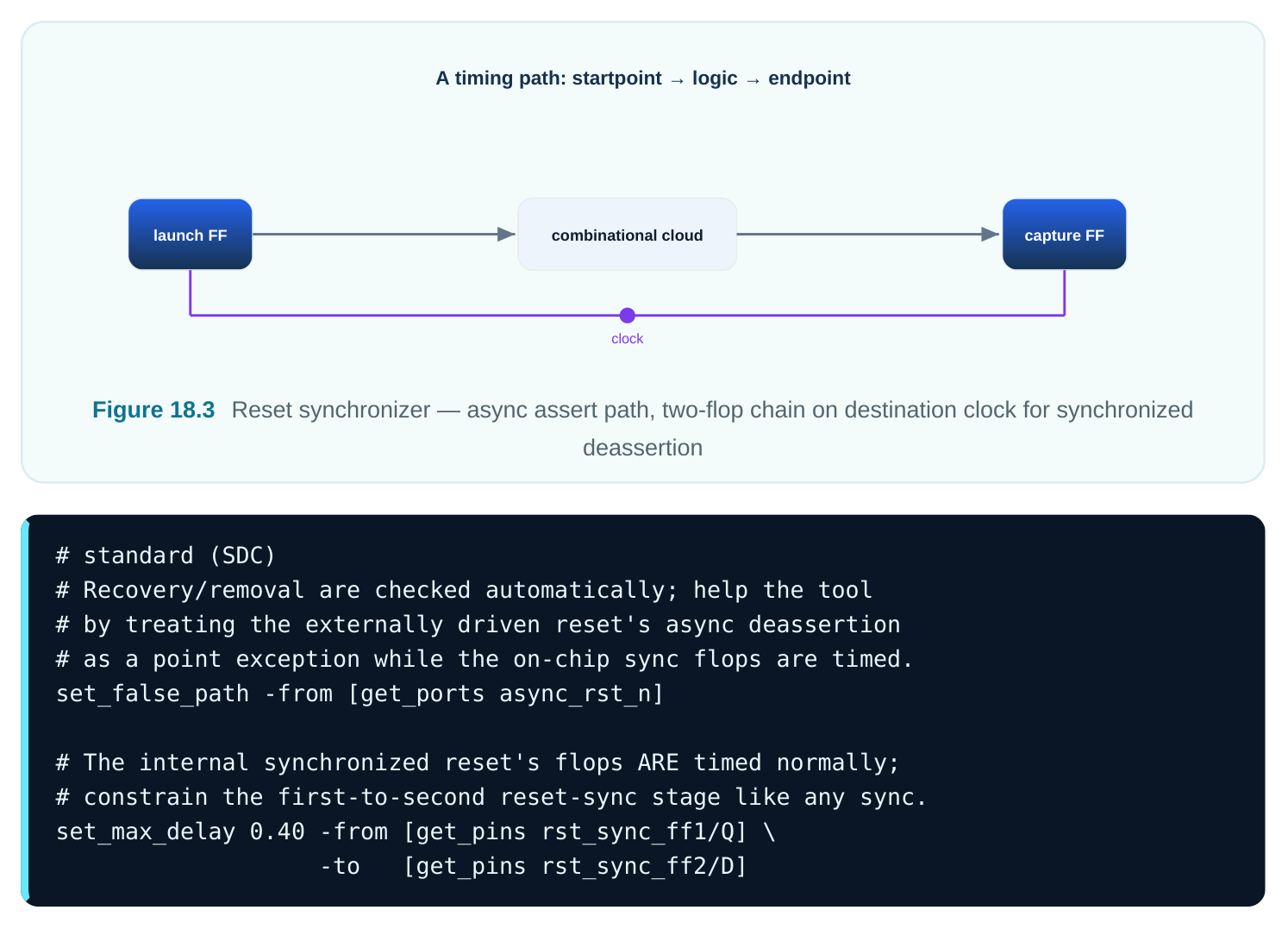
As with data synchronizers, false-pathing the external async edge does not excuse the internal flops. Their recovery/removal and setup must still pass.
What STA Checks vs. What CDC Tools Check
STA is a timing engine. It does not know a path is a synchronizer. It does not know a bus should be Gray coded. It will gladly time a structurally broken design as clean if you false-path the right arcs. Checking the structure is the job of dedicated CDC tools. These are structural and formal tools. The two kinds of tools work together.
| Concern | STA | CDC structural/formal tool |
|---|---|---|
| Setup/hold on synchronous paths | Yes | No |
| Recovery/removal timing | Yes | No |
| Settling-budget (max-delay on FF1→FF2) | Yes | No (relies on STA) |
| Is every async crossing synchronized? | No | Yes |
| Multi-bit coherency / Gray-code check | No | Yes |
| Convergence/reconvergence of synced signals | No | Yes |
| Glitch on combinational logic feeding a sync | No | Yes |
| Missing/incorrect synchronizer topology | No | Yes |
You need both a clean STA run and a clean CDC run. Neither replaces the other. The most dangerous case is a team that false-paths all async crossings to quiet STA and never runs structural CDC. STA goes green while real silicon corrupts data.
Worked Example — MTBF With Numbers
Take a destination flop with τ = 60 ps and T0 = 25 ps. The destination clock runs at f_clk = 400 MHz, so the period is 2.5 ns. The asynchronous data toggles at f_data = 40 MHz. Single flop, no settling (ts ≈ 0): The susceptibility rate is f_clk × f_data × T0 = 4e8 × 4e7 × 25e-12 = 0.4 failures per second. That is catastrophic. Two-flop synchronizer. FF1 gets nearly a full period to resolve. Allow setup plus uncertainty of 0.5 ns. So ts ≈ 2.5 − 0.5 = 2.0 ns .
ts / τ = 2.0e-9 / 60e-12 = 33.33
exp(33.33) ≈ 2.99e14
MTBF ≈ 2.99e14 / 0.4 ≈ 7.5e14 seconds ≈ 24 million years
Likely fine, but check the margin for a critical product. Add a third flop. This grants about two periods minus margins, say ts ≈ 4.5 ns :
ts / τ = 4.5e-9 / 60e-12 = 75
exp(75) ≈ 3.7e32
MTBF ≈ 3.7e32 / 0.4 ≈ 9.3e32 seconds — vastly longer than the universe's age
One extra flop bought about 18 more orders of magnitude of MTBF for one cycle of latency. This is the exponential leverage of ts . It is why "just add a flop" is the right reflex when MTBF is marginal.
Worked Example — Constraining a 2-FF Synchronizer's First Stage
Destination period = 2.5 ns. FF2 setup = 0.18 ns. Clock uncertainty = 0.12 ns. The settling budget you want to keep is everything left after those:
ts_target = 2.5 − 0.18 − 0.12 = 2.20 nsThat budget is spent by the FF1 clock-to-Q plus the FF1→FF2 interconnect. Let the router wander, and interconnect could eat, say, 1.1 ns. That shrinks the resolution time and quietly cuts MTBF by orders of magnitude. To cap it, constrain the segment well under the budget:
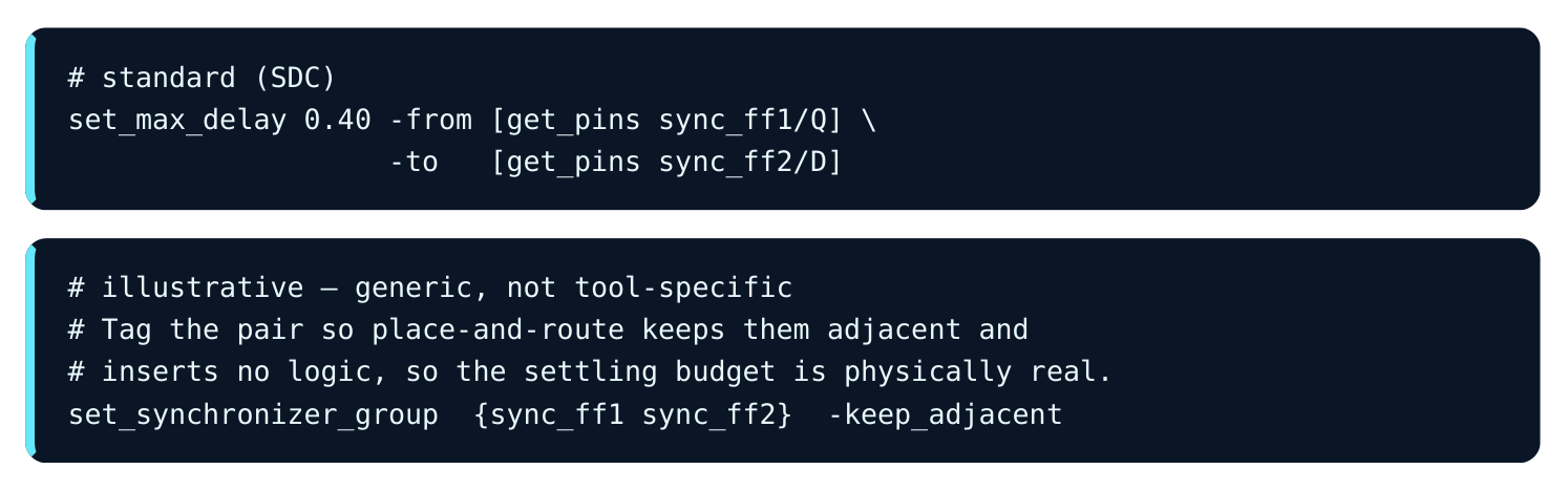
Hold FF1/Q→FF2/D to 0.40 ns. Take FF1 clock-to-Q at about 0.12 ns. Then the metastable node has roughly 2.20 − 0.12 − 0.40 ≈ 1.68 ns of clean exponential resolution before FF2 samples. And that 0.40 ns is now an enforced, signed-off number. It is no longer an accident of routing.
Interview Q&A
Setup needs a fixed time between launch and capture edges. Asynchronous clocks have no fixed phase. They drift, so every gap, including near zero, eventually happens. The check cannot be met. And the real risk, sampling a transition, is not a delay problem at all. So you false-path it and rely on a synchronizer.
classic bug. The FF1→FF2 segment is inside the destination domain and fully synchronous. It must be timed normally for setup and hold. It usually gets a max-delay to protect the settling budget. The false path only removed the meaningless cross-domain check.
ts . A third flop roughly doubles ts , adding one more destination period. Because of exp(ts/τ) , that can add tens of orders of magnitude of MTBF for just one extra cycle of latency.
metastability on its own. So in a cycle where several bits change, you can catch a mix of old and new bits. That is a value never transmitted. You need coherency mechanisms: Gray coding (one bit changes per step), a handshake, or an async FIFO.
crossing? Recovery is the least time reset must deassert before a clock edge. Removal is the least time it must stay asserted after the edge. If async reset deassertion breaks these, the flop can go metastable on release. The fix is a reset synchronizer: assert asynchronously, deassert synchronously through two flops.
structure. It cannot tell whether every async crossing is actually synchronized. It cannot tell whether a multi-bit bus is coherent or Gray coded. It cannot tell whether logic glitches feed a synchronizer, or whether synced signals reconverge unsafely. Structural and formal CDC tools check those. Both clean STA and clean CDC are required.
Key Takeaways
- STA can only check setup/hold where a fixed phase relationship exists. Truly async crossings have none. So the cross-domain check is meaningless and must be false-pathed, preferably via
set_clock_groups -asynchronous. - Metastability is the regenerative latch sitting near its unstable balance point. It resolves with time constant τ. MTBF rises exponentially with the settling time
tsyou grant. It can be made negligible but never zero. - Two- and three-flop synchronizers buy
tsby leaving one or two destination periods for FF1 to resolve before fan-out. More flops mean exponentially higher MTBF at the cost of latency. - False-pathing the crossing does not excuse the synchronizer's internal segment. Time FF1→FF2 normally and add a max-delay to keep the settling budget. Hold still applies.
- Multi-bit async buses need Gray coding, handshakes, or async FIFOs for coherency. Never use parallel per-bit synchronizers.
- Async reset deassertion needs recovery/removal safety. Get it with a reset synchronizer: async assert, sync deassert.
- STA and CDC tools split the work. STA owns timing, including settling-budget and recovery/ removal. Structural and formal CDC owns topology and coherency. Ship only when both are clean.
Comments
Leave a Reply